外文翻译--刀具成本的检测.doc

W12X2000型四辊卷板机设计【7张CAD图纸】【优秀】

收藏

压缩包内文档预览:(预览前20页/共62页)
预览图 预览图 预览图 预览图 预览图 预览图 预览图 预览图 预览图 预览图 预览图 预览图 预览图 预览图 预览图 预览图 预览图 预览图 预览图 预览图
编号:295553    类型:共享资源    大小:2.13MB    格式:RAR    上传时间:2014-07-09 上传人:上*** IP属地:江苏
45
积分
关 键 词:
W12X2000型 四辊卷板机 设计 cad图纸
资源描述:

W12X2000型四辊卷板机设计

60页 12000字数+说明书+外文翻译+7张CAD图纸【详情如下】

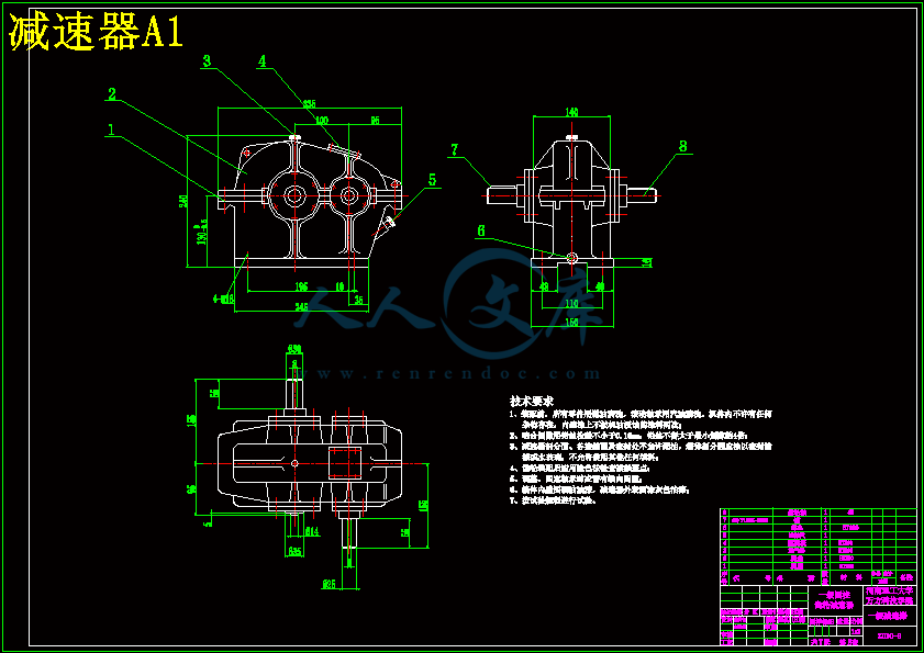
减速器A1.dwg

W12X2000型四辊卷板机设计论文.doc

外文翻译--刀具成本的检测.doc

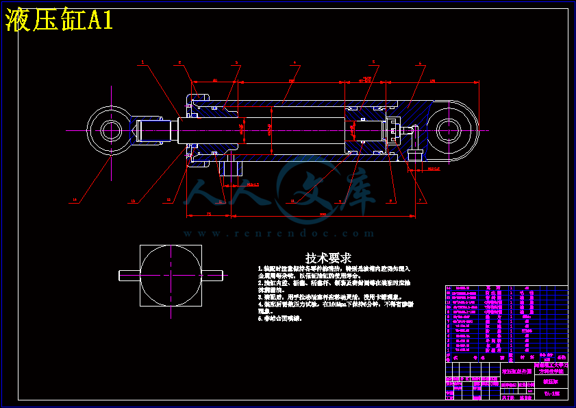
液压缸A1.dwg

端盖A3.dwg

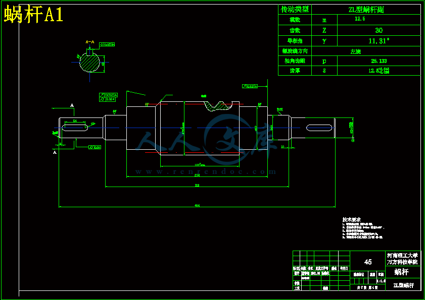
蜗杆A1.dwg

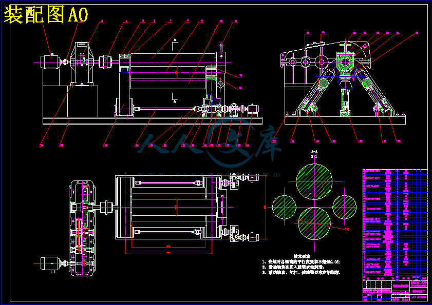
装配图A0.dwg

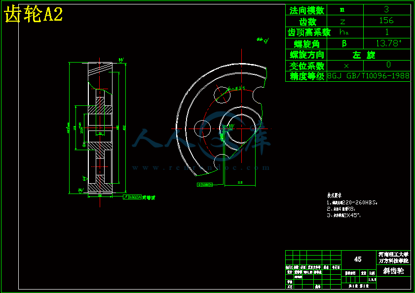
齿轮A2.dwg

齿轮轴A2.dwg

摘    要

   本说明书是按照所设计的卷板机内容撰写的,主要包括卷板机轴辊的受力分析、电动机的选择、主减速器的设计、侧辊传动系统的设计、下辊液压传动系统的设计以及对下辊液压同步控制系统进行了研究。从而保证了下辊在上升的过程中始终能够保持两端同步。

   四辊卷板机主要为锅炉厂辊制锅炉圆筒而设计,它可以用于各种型号锅炉圆筒的生产和加工,也在造船、石油化工、航空、水电、装潢、及电机制造等工业领域得到了广泛的应用,用以把金属板料卷制成圆筒、圆锥以及弧形板等各种零件。

   该四辊卷板机利用其四个辊筒的空间布置,最大范围地减少了剩余直边的出现、降低了生产成本、提高了生产效率。 

关键词:四辊卷板机   辊制   剩余直边   弧形板

Abstract

  This statement is in accordance with the design cylinder content written mainly include the pressure analysis of cylinder axle roller, electric motors choice, the reducer design, lateral roller drive train system design, the design of the roller hydraulic drive train system on the roller and hydraulic control systems simultaneously conducted research. Thereby ensuring an increase in the course of the roller always able to maintain both simultaneously.  

  The four cylinder roller machine mainly boiler plant roller system designed boilers cones, which can be used for various types of boilers cones production and processing are also shipbuilding, petrochemical, aviation, utilities, furniture, and electrical manufacturing industries widely applied to the metal plate material volumes produced cones, circular cone arc boards and various parts.  

  The four cylinder roller machine use its four roller cylinders space layout, the greatest scope to reduce the margin in the remaining departments, reducing production costs, improving production efficiency.

Key words:  four-cylinder roller machine    Roller machineLeft straight-side    Arc board

目  录

前 言1

第1章  绪   论2

1.1卷板的分类及特点2

1.2卷板机的分类及特点2

1.3 W12X2000型四辊卷板机的用途5

1.4 传动系统设计6

第2章  卷板机轴辊受力分析7

2.1作用在卷板机辊子上的弯曲扭矩7

2.2卷板机的空载扭矩8

2.3四辊卷板机的卷板力8

第3章  电动机的选择与计算12

3.1功率计算12

3.2电动机的选择12

第4章 主减速器的设计14

4.1电动机的确定14

4.2 传动比的分配15

4.3传动系统的运动和动力参数设计15

4.4 高速级斜齿圆柱齿轮传动的设计计算17

4.4.1选择精度等级,材料和齿数17

4.4.2 按齿面接触强度设计17

4.4.3按齿根弯曲疲劳强度设计21

4.4.4几何尺寸计算21

4.5中间级斜齿圆柱齿轮传动的设计计算22

4.5.1选择精度等级,材料和齿数22

4.5.2. 按齿面接触强度设计22

4.5.3.按齿根弯曲疲劳强度设计24

4.5.4几何尺寸计算26

4.6 低速级斜齿圆柱齿轮传动的设计计算:26

4.6.1选择精度等级,材料和齿数26

4.6.2. 按齿面接触强度设计27

4.6.3按齿根弯曲疲劳强度设计29

4.6.4几何尺寸计算30

4.7高速轴的设计以及轴的校核32

第5章 侧辊传动系统的设计36

5.1侧辊电动机的确定36

5.2侧辊减速器的确定36

5.3蜗轮蜗杆传动设计36

第6章 下辊筒液压缸的设计41

6.1下辊液压系统的工作原理41

6.2下辊筒液压缸设计42

第7章 辊筒轴的强度校核47

第8章 专题论文50

8.1前言50

8.2四辊卷板机工作原理50

8.3液压同步控制系统研究及设计原理52

8.4.结论53

致  谢54

参考文献55

   我所设计的这台四辊卷板机由四个辊筒所组成,其中一个上辊、两个侧辊和一个下辊。最大可以将40mm厚、2m长的钢板卷曲成圆柱、圆锥或其一部分。

   上辊为主传动,由主电动机通过主减速器和联轴器与上辊筒相连接,为卷制钢板提供扭矩;下辊作垂直升降运动,通过液压缸内的液压油作用于活塞而获得,以便夹紧板材,为液压传动,在下辊的两侧设有两个侧辊,侧辊可以沿着机架导轨做倾斜运动,由侧辊电动机通过一个单级减速器把扭矩传到丝杆丝母蜗轮蜗杆传动副,这样既达到了传递扭矩的作用,同时也改变了运动方向。

   在本次设计中,我设计了一套液压同步控制系统,通过控制电磁换向阀的通断,来控制下辊两端液压缸的同步上升,达到在下辊上升的过程中,下辊中心线能够始终同上辊中心线保持水平,这样就可以避免因钢板位置偏离中间位置,而使下辊受力不均匀,使下辊在上升的过程中一端受力大,一端受力小,使卷出来的圆筒一端大而一端小的情况发生。

   本次毕业设计是一次大型综合的设 计,通过这次做毕业设计使我对大学四年所学的知识有了更加深刻的回顾,也培养了我使用工具书的能力,同时它也是对我大学四年所学知识的一次检验。通过做毕业设计使我学习到了许多在课本上面所学习不到的致知识,也提高了我的动手能力。相信他们都是我在未来工作中能够用得上的。第1章  绪   论

 近些年随着原子能、石油化工、海洋开发、宇航、军工等部门的迅速发展,卷板机作业的范围正在不断的扩大,要求也在不断提高,现在卷板机已经广泛应用于锅炉、造船、石油化工、航空、水电、装潢、金属结构等行业中,用于将金属板材卷制成圆柱、圆锥或者将任意形状卷曲成圆柱形或其一部分。  

1.1卷板的分类及特点

   卷板按照工作状况分为:冷卷和热卷两种。冷卷的精度高,操作方便,要求钢板不能有缺口及裂缝等缺陷,有时还需在滚弯前进行正火或退火处理。热卷的最大缺陷是产生氧化皮及明显热膨胀。因此,只有当弯制的板超过机器的冷卷能力或弯曲较大时,才能使用热卷法,但冷卷的板料厚度范围目前正在日益扩大。生产也应根据不同卷制方法的特点结合具体情况适当选用。例如有些不允许冷卷的刚度太差,而且弯曲困难。如果采用温卷的方法就比较合适。 

1.2卷板机的分类及特点

   卷板机按照辊筒数量布置形式分为:四辊式卷板机和三辊式卷板机,其中三辊又可以分为对称式和不对称式两种。对称式三辊卷板机:结构紧凑,重量轻,易于制造、维修,投资小,两侧辊可以作得很近,成形准确。但是剩余直边大,一般对称三辊卷板机减小剩余直边比较麻烦。(如图1.1-2所示)

   不对称三辊卷板机是一根下辊轴和上辊轴中心水平距离到极小位置,另一根下辊轴放在侧边,所以滚出的零件仅起始端有直边。这样在滚零件时,正反两次辊制就可以消除直边问题。(如图1.1-1所示)其缺点为:在滚弯时大大增加了辊轴的弯曲力,使辊轴容易弯曲,影响零件的精度,坯料需要调头,弯边,操作不方便,辊筒受力较大,弯卷能力较小。

 图1.1-1非对称式卷板机               图1.1-2对称式卷板机

   卷板机按辊位调节方式可以分为:上调式和下调式两种,其中上调式可以分为横竖上调式(机械或液压调节);垂直上调式;下调式又可以分为不对称下调式(机械或液压调节);对称下调式(含垂直下调式)(液压调节)水平下调式(液压调节)。

   垂直下调式:结构简单、紧凑;剩余直边小,有时设计成上辊可以沿轴向抽出的结构。它的缺点是:弯板时,板料有倾斜动作,对热卷及重型工件不安全,长坯料必须先经初弯,否则会碰地面。

   水平下调式:较四辊卷板机的结构紧凑,操作方便剩余直边小,坯料始终保持在同一水平面,进料安全方便。其缺点是:上辊轴承间距较大,坯料对中不如四辊卷板机方便。

   横竖上调式:如图1.1-3,调节辊筒的数目最少,具有各种三辊的优点,而且剩余直边小。其缺点:设计时结构复杂不易处理。   卷板机按照辊筒方位,可以分为立式和卧式。按上辊受力类型,可以分为闭式(上辊中部有托辊)和开式(上辊无中部托辊),其中开式又可以分为有反压力装置的和无反压力装置的。

   立式:如图1.1-4,消除了氧化皮压伤,矩形板料可保证垂直进入辊间,防止扭斜,卷薄壁大直径,长条料等刚性较差的工件时,没有因自重而下榻的现象,板样测量较准,占地面积小。其缺点是:短工件只能在辊筒下部卷制,辊筒受力不均匀,易呈锥形;工件下端面与支撑面摩擦影响上下曲率的均匀性,卸料及工件放平料不方便,非矩形坯料支持不稳定。

   闭式:如图1.1-5 没有活动轴承机构结构较简单,上辊加中间支承辊后可作得很细可弯到较大的曲率,上辊刚度好,工件母线直线度好,下辊间距小,可卷薄板且曲率较准确,上辊行程大,有足够的位置装模具,可以作长拆边机用,但只能卷制圆心角小于180度的弧形板。   四辊卷板机有四个辊,(如图1.1-6所示)上辊是主动辊,下辊可以上下移动,用以夹紧钢板,两个侧辊可以沿斜向升降,在四辊卷板机上可进行钢板的预弯工作,它靠下辊的上升,将钢板端头压紧在上下辊之间,再利用侧辊的移动使钢板端部发生弯曲变形,从而达到所要求的曲率。

   它的优点是:

预弯及卷圆时,钢板可不调头。

上下辊能夹紧钢板,防止弯曲时滑脱。

侧辊能起定位作用,在进料时可使钢板找正。

   4、便于弯曲锥形件,椭圆形件及仿形加工。

   综合以上各种卷板机的综合特点,在本次毕业设计中我选择了W12 40X2000型四辊卷板机进行设计

1.3 W12X2000型四辊卷板机的用途

   W12X2000型四辊卷板机是专供金属板的卷曲和弯曲圆筒之用,是锅炉、造船、石油化工、水泥、电机及电器制造业中的主要设备之一。在常温的情况下,它可以将长达2m,厚度达40mm的钢板弯曲成圆柱面、圆锥面或任意形状的柱面或其一部分,在加热的情况下,它可以将长达2m,厚度达70mm的钢板卷曲成圆柱形或其一部分,它可以对一些厚度大,用常规方法无法弯卷的钢板进行加工,在加工的过程中它还可以对金属板端部进行直接弯曲,免去了端部预弯的工序,这是四辊卷板机比一般三辊卷板机优越之处。因此,W12X2000型四辊卷板机在锅炉、造船、石油化工、水泥、电机及电器制造业中得到了广泛应用。同时,这种设备的上市大大减轻了工人的劳动强度,提高了企业的效益。   W12 40X2000型四辊卷板机是以上辊为主动辊,由主电动机通过主减速器及联轴器,从而带动上辊工作,下辊的作用是提供一定的向上力,(设该力为夹紧力W),与上辊一起夹紧所卷钢板,使上辊与被卷钢板间产生足够的摩擦力,在上辊旋转时能够带动钢板运动。两个侧辊用以形成卷筒所需的曲率,使板料达到所需的目的。

   在我设计的这台四辊卷板机中,我采用了由主电动机通过主减速器以及联轴器,从而带动上辊的旋转。而下辊的运动我采用在下辊的两端各放一个液压缸,通过液压缸内的液压油作用于活塞而使下辊能够实现上下的升降运动,以便夹紧钢板,用液压系统来控制下辊筒的升降以及两个液压缸在上升的过程中保持同步上升。在下辊的两侧设有两个侧辊,两个侧辊分别由两个电动机通过两个单级减速器以及联轴器带动;两个电动机可以分别单独控制也可以同时控制,两个侧辊可以沿着机架导轨做倾斜运动,通过丝杆丝母蜗轮蜗杆传动。

参考文献

濮良贵,纪名刚主编. 机械设计(第七版).北京:高等教育出版社, 2002

垄桂义主编. 机械设计课程设计图册.北京: 高等教育出版社, 2000

沈兴全,吴秀玲主编. 液压传动与控制.北京: 国防工业出版社, 2005

黎启柏主编. 液压元件手册. 北京:机械工业出版社, 2000

任金泉主编. 机械设计课程设计. 陕西:西安交通大学出版社, 2003

刘品,刘丽华主编. 互换性与测量技术基础. 黑龙江:哈尔滨工业大学出版社, 2001

机械工程手册编委会主编. 机械工程手册(第7卷). 北京:机械工业出版社, 1982

机械设计手册编委会主编. 机械设计手册(第3卷).北京: 机械工业出版社, 2004

王宪军,赵存友主编. 液压传动. 黑龙江:哈尔滨工程大学出版社, 2002

赵铁主编. 液压四辊卷板机同步控制系统的研究与改进.河南: 焦作工学院学报,1996,6:(3)3338

王大川,沈利蓉主编. 卷板机轴辊的受载分析及板裁曲率半径的确定.山西: 山西煤炭.2002,12:(4)45-46

王青主编. 80X2800mm卷板机设计. 内蒙古:包钢科技. 1997(4):134-136

苏传德主编. 卷板机电机驱动功率的计算. 山东冶金. 1999,6(3):42-43

成其谦,吴荣昌主编. W12四辊卷板机改造. 制造与工艺. 2000,6(2):29-32

常英丽,刘晓涵主编. Z31900SM型四辊卷板机技术改进.2004,(7):101-102

内容简介:
河南理工大学万方科技学院本科毕业论文附录:外文资料和中文翻译外文资料:Testing of Tool Life CostMachining cost is the sum of the machine tool cost and the cutter cost. The machine cost consists of idle cost, machining cost, and tool changing cost. The machining cost decreases with increased cutting speed; while the idle cost remains constant with changes in cutting speed. From the machining data handbook 24 the generalized machining cost equation is listed below: In order to optimize the cutting condition, it is essential to determine the mathematical relationship between the cuttings inserts type and cutting speed. In our study Taylors model will be used in relating the cutting tool life to the cutting speed:VT =C V= cutting speedT= Cutting time to produce a standard amount of flank wear (e.g. 0.2mm) n and C are constants for the material or conditions used.In order to determine constants n and C for the cutting inserts under study in machining 4140 steel and the conditions used in the experiments, a LogV against LogT is drawn and shown for the three types of cutting inserts under study Figure 1, Figure 2are for KC313 under dry and wet conditions, Figure 3, and Figure 4are for KC732. In addition, Figure 6, and Figure 7are for KC5010. It can be seen from the aforementioned figures that in-spite of considerable scatter in test measurements, the results fall reasonably well on a straight line. From the curves it can be seen that for the same cutting speed the tool life increases by increasing the wear criterion and introduction of coolant emulsion for KC313 and KC732. However, as seen in KC5010 tool life increases by increasing the wear criterion and decreases by introducing coolant. This negative behavior of KC5010 toward coolant emulsion and the effect of wear mechanisms behind it will be covered in Chapter 5. As well as the wear kinds on other inserts investigated in this research.Metal cutting studies focused on tools wear, tool life, and wear mechanisms. However, future research should pay more attention to other factors as well:l Wear criterion value set up by the factory system, which basically the tool wear threshold value that suits the factory product.l Types of tools used, such as carbide tips and high speed tools. Studying the variation of tool life wear under dry and wet cutting that effect the tool life equation constants (C,n) is useful. This will improve tool life because it also affects the economy of cutting 24.In order to determine the effect of cutting fluid on the selected wear criterion, relationship between different wear criteria and machining cost for the cutting inserts under HSM must be studied. The value of the tool life constants (C,n) for different wear criteria are extracted and plotted within the ranges listed in table (1). The values of the constants (C, n) extracted from Figure 1/B, Figure 3IB, and Figure 3-10 are shown in tables1 and 2. Further explanation of the relationship between these parameters and wear criteria will be covered through out the next figures. Figure5represents the relationship between n and wear criterion. As wear criterion increase n.(a) Log (time) versus Log (speed) at different wear criteria (dry condition).(b) Log (time) versus Log (speed) at different wear criteria (wet condition)Figure 2Time versus speed at different wear criteria KC313. (a) Log (time) versus Log (speed) at different wear criteri(drycondition). (b) Log (time) versus Log (speed) at different wear criteria (wet condition).(a) Log (time) versus Log (speed) at different wear criteria (dry condition)(b) Log (time) versus Log (speed) at different wear criteria (wet condition).Figure 3Time versus speed at different wear criteria KC732 (a)Log (time) versus Log(speed) at different wear criteria (dry condition), (b) Log (time) versus Log (speed) at different wear criteria (wet condition)(a) Log (time) versus Log (speed) at different wear criteria (dry condition).(b) Log (time) versus Log (speed) at different wear criteria (wet condition)Figure 3-10 Time versus speed at different wear criteria KC5010 (a) Log (time) versus Log(speed) at different wear criteria (dry condition), (b) Log (time) versus Log (speed) at different wear criteria (wet condition).Table 1 Ranges of plotted tool life constants.RangeCutting InsertCondition0 LogT 2.6KC313Dry0 Log T 4.1KC313Wet0 LogT 2.6KC5010Dry0 Log T 1.75KC5010Wet0 LogT 2.1KC732Dry0 Log T 2.4KC732WetTable 2 Wear Criteria versus C and n for three cutting inserts (Dry Condition).WearCriteria(mm)KC 313KC 5010KC732CnCnCnconstantconstantconstantconstantconstantconstant0.151420.2605180.2486300.2880.21650.2125600.2649640.3640.251960.2405960.27810990.3710.32380.2936050.27912330.3930.352500.2756120.27913990.4210.42630.2816250.28115030.4340.452820.2926250.27815170.4340.52920.2946300.27615770.4420.553020.2966320.27415920.4430.63130.3006380.27416110.444Table 3Wear Criteria versus C and n for three cutting inserts (Wet Condition).KC 313KC 5010KC732Wear criterion(mm)CnCnCn0.151670.2014970.298881.0500.3320.21870.2106190.3101051.960.3530.252280.2406100.3121297.180.39300.32440.2506280.3091545.250.42400.352670.2606260.3001782.380.45400.42910.2806190.2901918.670.46800.453380.3106150.2822137.960.49100.53030.3106160.279 2477.420.52400.553970.3406180.2782837.920.55400.64220.3506260.2793243.390.5830values increase for both cutting conditions. In addition, n values for wet condition is lower than dry conditions up until wear criterion 0.38 after which n for wet starts to get bigger. Figure 5 shows C values versus wear criterion, and reveals C increases as the wear criterion increases for both dry and wet cutting. However, C values under wet condition are getting higher than under dry conditions. This proves the increase in tool life by introducing coolant emulsion and by increasing the wear criterion for this cutting tool material during cutting.Next, Figure 6represents values of n with respect to wear criterion for KC732 material under dry and wet conditions. As the wear criteria increase n values increase. Furthermore, wear curve is higher than dry curve. Figure7 presents a proportional relationship between constant C values and wear criterion. However, wet C curve is higher than dry curves, which indicates the benefit of using coolant emulsion for material KC732. This benefit becomes more essential by increasing the wear criterion. The higher the C value; the higher the tool life becomes. Figure8shows the effect of introducing coolant emulsion on cutting tool performance. Therefore, the higher n; the lower the tool life is. Figure9shows the drop in C values by increasing the wear criterion and coolant usage; thus indicating a shorter tool life in wet cutting condition. During the previous curves of KC313 and KC732 materials, the increase in n values was an indication off shortened tool life. However, the huge increase in wet C curves over dry C over compensated the drop and elongated tool life for KC313 and KC732. In contrast, the case is for KC5010. Figure 12 and Figure 10 are for uncoated cemented carbide (KC313). It shows the relationship between cost cutting speeds for different wear criteria under dry and wet cutting.(a) n values versus wear criterion (wet and dry).(b) C values versus wear criterion (wet and dry).Figure 11Taylors constants for KC313 versus wear criteria,(a) n values versus wear criteria (wet and dry), (b) C values versus wear criteria (wet and dry).(a) n values versus wear criterion (wet and dry).(b) C values versus wear criterion (wet and dry).Figure 12Taylors constants for KC732 versus wear criteria, (a) n values versus wear criteria (wet and dry), (b) C values versus wear criteria (wet and dry).(a) n values versus wear criterion (wet and dry). (b) C values versus wear criterion (wet and dry)Figure 13 Taylors constants for KC5010 versus wear criteria, (a) n values versus wear criteria (wet and dry), (b) C values versus wear criteria (wet and dry).Both conditions indicate as the wear criteria increases the machining cost decreases. Nonetheless, as the speed increases the cost reaches optimum value and then increases. Figure 14 and Figure 3-15B show economical comparison between dry and wet cutting at (0.4 and 0.6 mm) wear criterion. Optimum cutting speed for dry cutting is 90 m/min while 120 m/min is for wet cutting.Cost as a function of speed is presented in Figure15 and Figure 16 for sandwich coating (KC732) under dry and wet conditions. Again, as wear criteria increases, cost decreases. Furthermore, the optimum speed of 260 m/min of dry cutting, increased to 360 m/min in cases of wet cutting. This indicates the importance of coolant with this material not only decreases cost but also increases productivity.Figure 3-17A and Figure 17 summarize the relationship of cost and speed for coated tools with TiALN (KC5010) under dry and wet cutting conditions. As the cutting speed increases the cost increases and as the wear criteria increases the cost decreases. The optimum cost was at the lowest speed (210 m/min) in both machining conditions.A cost comparison between KC732 and KC5010 at different wear criteria and machining conditions is presented in Figures 18 and19. It can be seen that KC732 responded positively to coolant in terms of extended tool life, and increased the optimum cutting speed from 260m/min to 360 nn/min. Nonetheless, coolant introduction to KC5010 at high speed cutting lowered the tool life and increased machining cost. The data presented in the aforementioned figures shows that dry cutting is more cost effective than wet cutting within speed range of 210 m/min-310 m/min for KC732 and vise versa at any speed higher than 310m/min. Cutting tool material KC5010 is cost effective at dry and 210 m/min. Therefore, in spite of the cost of the KC732; it is proven to be superior over KC313 (uncoated) and KC5010 in wear cost. Table 3 summarizes the optimum values of cost and speed under wet and dry cutting.Figures18, and 17for KC313 (uncoated) show the relationship between costs and wear criterion at different cutting speeds under dry and wet conditions. Figure 20, and Figure 21 are plotted for KC732 presenting cutting cost as a function of wear criteria for dry and wet conditions. Figure 3-21A and Figure 3-21B are plotted for KC5010. The curves show that for the same cutting velocity, by increases the selected wear criterion, the cost decreases.The improved performance of (KC313) under wet over dry cutting in terms off tool life is presented in Figure 22. The results of the two coatings testing methods, of flank wear for the KC732 and KC5010 are shown in Figure 23. Clearly this indicates improvement in cutting inserts life with TiN-TiCN-TiN coatings (KC732) under wet over dry cutting, and reduction in tool life of TiALN coating (KC5010) on wet cutting. Finally, KC732 provides superior performance under all cutting conditions over KC5010.(a) The variation of cost versus cutting speed at different wear criteria (dry ).(b) The variation of cost versus cutting speed at different wear criteria (wet).Figure 23 Cost variation with speed for KC313, (a) The variation of cost versus cutting speed at different wear criteria (dry), (b) The variation of cost versus cutting speed at different wear criteria (wet).(a) The variation of cost versus cutting speed at 0.4mm wear criterion. (b) The variation of cost versus cutting speed at 0.6mm wear criterionFigure 24 Cost versus speed comparison at wet and dry at two values of wear Criterion: (a) The variation of cost versus cutting speed at 0.4mm wear Criterion, (b) The variation of cost versus cutting speed at 0.6mm wear criterion.(a) The variation of cost versus cutting speed at different wear criteria (dry ). (b) The variation of cost versus cutting speed at different wear criteria (wet).Figure 25 Cost variation with speed for KC732, (a) The variation of cost versus cutting speed at different wear criteria (dry), (b) The variation of cost versus cutting speed at different wear criteria (wet).(a) The variation of cost versus cutting speed at different wear criteria (dry ).(b) The variation of cost versus cutting speed at different wear criteria (wet).Figure 26 Cost variation with speed for KC732, (a) The variation of cost versus cutting speed at different wear criteria (dry), (b) The variation of cost versus cutting speed at different wear criteria (wet).(a) Cost versus speed at 0.4 mm wear criterion(b) Cost versus speed at 0.6 mm wear criterionFigure 27 Cost comparison between KC5010 and KC732 at different wear criteria (a) Cost versus speed at 0.4 mm wear criterion, (b) Cost versus speed at 0.6 mm wear criterion.Table4 Comparison between three cutting inserts at the same wear criterion Tool TypeWear criterion(mm)Optimum Cost/ Speed(m/min)DryWetKC3130.647$ /9040$/90KC50100.634$ /21036$/210KC7320.629$ /26028.84$/360(a) The variation of cost versus wear criterion at different cutting speeds (dry ).(b) The variation of cost versus cutting speed at different wear criteria (wet).Figure 26 Cost variation with wear criteria for KC313, (a): The variation of cost versus cutting speed at different wear criteria (dry), (b): The variation of cost versus cutting speed at different wear criteria (wet).(a)The variation of cost versus wear criterion at different cutting speeds (dry )(b)The variation of cost versus wear criterion at different cutting speeds (wet).Figure 3-20 Cost variation with wear criteria for KC732, (a): The variation of cost versus cutting speed at different wear criteria (dry), (b): The variation of cost versus cutting speed at different wear criteria (wet).(a) The variation of cost versus wear criterion at different cutting speeds (dry ).(b) The variation of cost versus wear criterion at different cutting speeds (wet).Figure 3-21 Cost variation with wear criteria for KC5010, (a) The variation of cost versus cutting speed at different wear criteria (dry), (b) The variation of cost versus cutting speed at different wear criteria (wet)(a) Tool life at 0.4 mm wear criterion for KC313 (dry & wet).(b)Tool life at 0.4 mm wear criterion of KC732 and KC5010 (dry &wet). Figure 3-22 Tool life comparison at 0.4 wear criterion under dry and wet(a) Tool life at 0.4 mm wear criterion for KC313 (dry & wet), (b) Tool life at 0.4 mm wear criterion of KC732 and KC5010 (dry &wet).The cutting inserts were retested at cutting speed values within the range of experimental testing speeds under dry and wet machining condition. The results presented are for the cemented carbide uncoated (KC313), cemented carbide coated with TiALN (KC5010), and for the KC732. Figures 3-23A and 3-23B show the theoretical and experimental results of machining KC313 at a cutting speed of 100 m/min, and 160 m/min respectively. A good agreement between theoretical and experimental values was noticed indicating the accuracy of Taylors formula in predicting the tool life. Figures 3-24A and 3-24B present theoretical and experimental results of machining KC5010, at two different cutting speeds 280 m/min and 390 m/min good agreement between both was noticed. Experimental and theoretical data for the KC732 are presented in Figures 3-25A, and 3-25B under 280m/min and 390m/min. In this section result samples were presented and the rest of figures are included in the appendix.(a) Theoretical and experimental results of machining KC313 at 100m/min.(b) Theoretical and experimental results of machining KC313 at 160m/min.Figure 3-23 Theoretical and experimental results for KC313 under wet and dry cutting at different speeds: (a) Theoretical and experimental results of machining KC313 at 100m/min, (b) Theoretical and experimental results of machining KC313 at 160m/min.(a) Theoretical and experimental results of machining KC5010 at 280m/min.(b) Theoretical and experimental results of machining KC5010 at 390m/min.Figure 3-24 Theoretical and experimental results for KC5010 under wet and dry cutting at different speeds: (a) Theoretical and experimental results of machining KC5010 at 280m/min, (b) Theoretical and experimental results of machining KC5010 at 390m/min.(a) Theoretical and experimental results of machining KC732 at 280m/min.(b) Theoretical and experimental results of machining KC732 at 390m/min.Figure 3-25 Theoretical and experimental results for KC732 under wet and dry cutting at different speeds: (a) Theoretical and experimental results of machining KC732 at 280m/min, (b)Theoretical and experimental results of machining KC732 at 390m/min.中文翻译:刀具成本的检测加工成本是加工工具成本和切削成本的总和。机床成本由闲置费用,加工费用和工具改变费用组成。当改变切削速度的情况下闲置费用保持不变。从机械数据手册24上表明机械设备成本的公式如下:Error! No bookmark name given.为了优化切割条件,必须确定切割深度大小和切割速度的数学关系式.在 我们学习的泰勒模型将被用于确定切削速度对切削刀具寿命的影响:VT =C -3-2V=切削速度T=切割时产生的标准金额侧翼磨损(例如.0.2毫米)N和C都是由被使用的材料或者工作条件所决定的常数. ,为了确定进给时的常数n和C我们以4140钢在实验的条件下进行研究,以LogV和LogT为坐标进行作图,画出了三种类型的进给图形,图1、图2是对KC313为研究对象在干和湿的条件下分别做出的图形,图3和图4是对KC732为研究对象在干和湿两种状态下所做的图形,另外,图5、图6是以KC5010为研究对象在干和湿两种状况下所做的图形. 从上述的图形可以看出不管测量的次数有多少,其结果都是呈直线分布的形式下降,从曲线我们能够看出,在相同的切削速度的条件下,增加磨损标准和对KC313和KC732使用冷却液都可以提高工具的使用寿命。然而,对于KC5010来说提高磨损标准和降低使用冷却液对提高KC5010工具寿命有好处。冷却乳液的这种抑制作用和对磨损机构的效果我们把它列入到了第五章。以及其他类型的磨损也将插入到那里研究。金属的切削研究主要集中在刀具的磨损、刀具的寿命和磨损机理。不过,未来的研究应该更加关注其他因素的影响:l 通过工厂体系建立磨损标准,基本的刀具磨损开端取决于工厂的产品。l 使用刀具的类型,向碳素钢刀具和高速切削刀具。这对于研究在干和湿的条件下研究影响刀具寿命的因素常数(C,n)是有用的。这将提高刀具的寿命,因为它也将影响到切削的经济性24。为了确定切削液在选择磨损标准时所起的作用,不同的磨损标准和经常的进给成本在HMS下必须被研究。不同切削标准的刀具寿命常数在表(1)所列的表格中被摘录和划分。从图7。图8、图9的常数(C,n)的价值在表1和表2中被反映出来。在以后的图中说明这些参数和磨损标准的关系。图10描述了n和磨损标准的关系。当提高n时磨损标准的变化。图1(a)以Log(T)和Log(V)为坐标在不同的磨损标准的情况下所做的图形(干条件)图2 (b)以Log(T)和Log(V)为坐标在不同的磨损标准的情况下所做的图形(湿条件)图2 KC313在不同的磨损标准下由时间(T)和速度(V)为坐标所做的图形(a)以Log(T)和Log(V)为坐标在不同的磨损标准的情况下所做的图形(干条件)(b) 以Log(T)和Log(V)为坐标在不同的磨损标准的情况下所做的图形(湿条件)图3(a)以Log(T)和Log(V)为坐标在不同的磨损标准的情况下所做的图形(干条件)图4(b)以Log(T)和Log(V)为坐标在不同的磨损标准的情况下所做的图形(湿条件)图3-9 KC732在不同的磨损标准下由时间(T)和速度(V)为坐标所做的图形(a)以Log(T)和Log(V)为坐标在不同的磨损标准的情况下所做的图形(干条件)(b) 以Log(T)和Log(V)为坐标在不同的磨损标准的情况下所做的图形(湿条件)图5(a) 以Log(T)和Log(V)为坐标在不同的磨损标准的情况下所做的图形(干条件)图6(b)以Log(T)和Log(V)为坐标在不同的磨损标准的情况下所做的图形(湿条件)图3 KC5010在不同的磨损标准下由时间(T)和速度(V)为坐标所做的图形 (a)以Log(T)和Log(V)为坐标在不同的磨损标准的情况下所做的图形(干条件) (b) 以Log(T)和Log(V)为坐标在不同的磨损标准的情况下所做的图形(湿条件)表1 刀具寿命常数的范围划分RangeCutting InsertCondition0 LogT 2.6KC313Dry0 Log T 4.1KC313Wet0 LogT 2.6KC5010Dry0 Log T 1.75KC5010Wet0 LogT 2.1KC732Dry0 Log T 2.4KC732Wet表2 在三种刀具材料下由C和n所做的磨损标准图(干条件下)WearCriteria(mm)KC 313KC 5010KC732CnCnCnconstantconstantconstantconstantconstantconstant0.151420.2605180.2486300.2880.21650.2125600.2649640.3640.251960.2405960.27810990.3710.32380.2936050.27912330.3930.352500.2756120.27913990.4210.42630.2816250.28115030.4340.452820.2926250.27815170.4340.52920.2946300.27615770.4420.553020.2966320.27415920.4430.63130.3006380.27416110.444表3 在三种刀具材料下由C和n所做的磨损标准图(湿条件下)KC 313KC 5010KC732Wear criterion(mm)CnCnCn0.151670.2014970.298881.0500.3320.21870.2106190.3101051.960.3530.252280.2406100.3121297.180.39300.32440.2506280.3091545.250.42400.352670.2606260.3001782.380.45400.42910.2806190.2901918.670.46800.453380.3106150.2822137.960.49100.53030.3106160.279 2477.420.52400.553970.3406180.2782837.920.55400.64220.3506260.2793243.390.5830在这两种条件下价值能够得到提高,另外,湿润条件n的价值要比干燥条件n的价值低,直到磨损标准达到0.38以后,干燥条件的n开始大于湿润条件的 n。图3-11B可以看出C在磨损标准所做的图形中,在干和湿的条件下磨损标准提高时 C也随之提高。然而,湿的条件下C的价值要比干的条件下高。这证明在整个切削过程中通过使用冷却液提高刀具的寿命和提高磨损标准都可以一直的保护切削刀具材料。接下来,图3-12A描述了KC732材料在干和湿的条件下n与磨损标准之间的关系。磨损价值随着n的提高而提高。此外,湿曲线要比干曲线高。图3-12B描述的一个常数C和磨损价值的比例关系。然而,湿条件的C曲线比干条件下的曲线高,这表面对于材料KC732来说使用冷却液是有益处的。更为重要的这有利于提高磨损标准。C的价值越高,刀具的使用寿命也就变的越高。图3-13A表明冷却液对刀具性能的影响。因此。n越高,刀具的使用寿命就越低。图3-13B可以看出通过使用冷却液和提高磨损价值可以降低C,这说明刀具在湿润的条件下,刀具的使用寿命比较短。之前研究的都是材料KC313和材料KC732,提高n就意味着刀具的寿命将被缩短。然而。大幅度的提高湿曲线C超过干曲线C的补偿下降,KC313和KC732的使用寿命将延长。与次相反。KC5010对此正好相反。图3-14A和图3-14B是没有被碳包裹的情况(KC313)。他表面了在干和湿的切削条件下不同磨损标准的切削速度的价值的关系。图7(a) n与磨损标准为坐标建立的关系图(干和湿条件下)图8(b) C与磨损标准为坐标建立的关系图(干和湿条件下)图3-11 KC313的以泰勒常数与磨损标准为坐标建立的关系图(a)n与磨损标准为坐标建立的关系图(干和湿条件下)(b) C与磨损标准为坐标建立的关系图(干和湿条件下)图9(a) n与磨损标准为坐标建立的关系图(干和湿条件下)图10(b) C与磨损标准为坐标建立的关系图(干和湿条件下)图3-12 KC732的以泰勒常数与磨损标准为坐标建立的关系图(a)n与磨损标准为坐标建立的关系图(干和湿条件下)(b) C与磨损标准为坐标建立的关系图(干和湿条件下) 图11(a) n与磨损标准为坐标建立的关系图(干和湿条件下)图12(b)C与磨损标准为坐标建立的关系图(干和湿条件下)图3-13 KC5010的以泰勒常数与磨损标准为坐标建立的关系图(a)n与磨损标准为坐标建立的关系图(干和湿条件下)(b) C与磨损标准为坐标建立的关系图(干和湿条件下).这两个条件表明当磨损标准增加的同时机床的成本下降。尽管如此,当成本增加的速度达到再增加就叨叨最佳时。图3-15A和图3-15B是由磨损标准在(0.4-0.6毫米)时,干和湿条件下经济性的比较。干切削的最佳切削速度是90米/分而湿切削的最佳切削速度是120米/分。在图3-16A和图3-16B中列出了在干和湿的条件下含有KC732涂层的速度与成本的函数关系。再次,当磨损标准增加的时候,成本下降。此外,干切削的最佳切削速度是260米/分,而湿切削的最佳切削速度是360米/分。这表面冷却液对这种材料很重要,它不仅可以降低成本,而且还可以提高生产率。图3-17A和图3-17B概括了在干和湿的条件下,对涂有TIALN的材料KC5010的切削速度和成本之间的关系。当切削速度提高时,切削成本也随之提高,当磨损标准提高,切削成本下降。在这两种切削条件下,最佳的切削成本是在速度最低达到210米/分的时候。图3-18A和图3-18B描述的是在不同的磨损标准和不同的切削条件下KC732和KC5010的切削成本的比较。它可以明确地反映出对于KC732来说,冷却液可以延长刀具的寿命。切削速度从260米/分到360米/分为最佳的切削速度。不过,对于KC5010来说在高速加工的情况下冷却液可以使它的刀具寿命降低而且使切削成本提高。从上面这些数据可以看出对于KC732来说,在速度为210米/分-310米/分的速度范围内干切削要比湿切削的经济效率高。当速度达到310米/分是效率最高。对于切削材料KC5010来说在干条件下速度为210米/分时切削成本有效。因此,不管KC732的成本,它的磨损都远远的超过没有处理的KC313和KC5010。表3-10总结了干和湿条件下的最佳切削速度和最佳的切削成本。图3-19A和图3-19B列出的是没有经过处理的KC313在干和湿的条件下,不同的切削速度下切削成本和磨损标准之间的关系。图3-20A和图3-20B列出了处理后的KC732在干和湿的条件下的磨损标准函数。图3-21A和图3-21B列除了KC5010在干和湿的条件下的磨损标准函数。曲线表面在切削速度相同的条件下,增加磨损标准,切削成本下降。在图3-22A表明在湿的条件下改变KC313的性能要比在干的条件下改变其性能使刀具的寿命降低。在图3-22B可以看出KC732和KC5010经过表面处理后的结果和侧面的磨损情况。这清楚的表明在湿润的条件下KC372表面涂TIN-TICN-TIN要比在干的条件下效果明显。在湿的条件下对KC5010表面涂TIALN会减少它的刀具寿命。最后,KC732在所有条件下它的切削性能都要远远的超过KC5010。图13(a) 在不同磨损标准下,切削速度与成本的关系图干切削条件下)图14
温馨提示:
1: 本站所有资源如无特殊说明,都需要本地电脑安装OFFICE2007和PDF阅读器。图纸软件为CAD,CAXA,PROE,UG,SolidWorks等.压缩文件请下载最新的WinRAR软件解压。
2: 本站的文档不包含任何第三方提供的附件图纸等,如果需要附件,请联系上传者。文件的所有权益归上传用户所有。
3.本站RAR压缩包中若带图纸,网页内容里面会有图纸预览,若没有图纸预览就没有图纸。
4. 未经权益所有人同意不得将文件中的内容挪作商业或盈利用途。
5. 人人文库网仅提供信息存储空间,仅对用户上传内容的表现方式做保护处理,对用户上传分享的文档内容本身不做任何修改或编辑,并不能对任何下载内容负责。
6. 下载文件中如有侵权或不适当内容,请与我们联系,我们立即纠正。
7. 本站不保证下载资源的准确性、安全性和完整性, 同时也不承担用户因使用这些下载资源对自己和他人造成任何形式的伤害或损失。
提示  人人文库网所有资源均是用户自行上传分享,仅供网友学习交流,未经上传用户书面授权,请勿作他用。
关于本文
本文标题:W12X2000型四辊卷板机设计【7张CAD图纸】【优秀】
链接地址:https://www.renrendoc.com/p-295553.html

官方联系方式

2:不支持迅雷下载,请使用浏览器下载   
3:不支持QQ浏览器下载,请用其他浏览器   
4:下载后的文档和图纸-无水印   
5:文档经过压缩,下载后原文更清晰   
关于我们 - 网站声明 - 网站地图 - 资源地图 - 友情链接 - 网站客服 - 联系我们

网站客服QQ:2881952447     

copyright@ 2020-2025  renrendoc.com 人人文库版权所有   联系电话:400-852-1180

备案号:蜀ICP备2022000484号-2       经营许可证: 川B2-20220663       公网安备川公网安备: 51019002004831号

本站为文档C2C交易模式,即用户上传的文档直接被用户下载,本站只是中间服务平台,本站所有文档下载所得的收益归上传人(含作者)所有。人人文库网仅提供信息存储空间,仅对用户上传内容的表现方式做保护处理,对上载内容本身不做任何修改或编辑。若文档所含内容侵犯了您的版权或隐私,请立即通知人人文库网,我们立即给予删除!