评阅评语表.doc

离合器壳体中心大孔冲孔、成型、修边复合模设计【优秀】【word+9张CAD图纸全套】【冲压复合模具类】【毕设】

收藏

资源目录
跳过导航链接。
压缩包内文档预览:
预览图 预览图
编号:298492    类型:共享资源    大小:964.20KB    格式:RAR    上传时间:2014-07-23 上传人:QQ14****9609 IP属地:陕西
45
积分
关 键 词:
离合器壳体 中心 冲孔 成型 复合 设计 优秀 优良 word cad 图纸 全套
资源描述:

离合器壳体中心大孔冲孔、成型、修边复合膜设计【优秀】【word+9张CAD图纸全套】【冲压复合模具类】【毕业设计】

【带任务书+开题报告+评阅评语表+指导教师评阅表+外文翻译+实习报告】【42页@正文20100字】【详情如下】【需要咨询购买全套设计请加QQ1459919609】

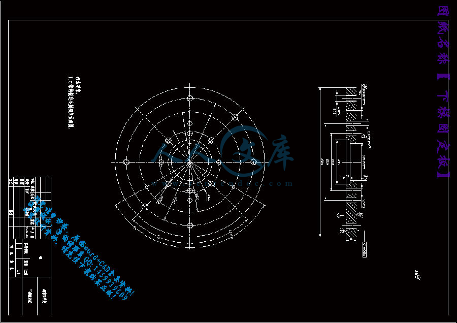
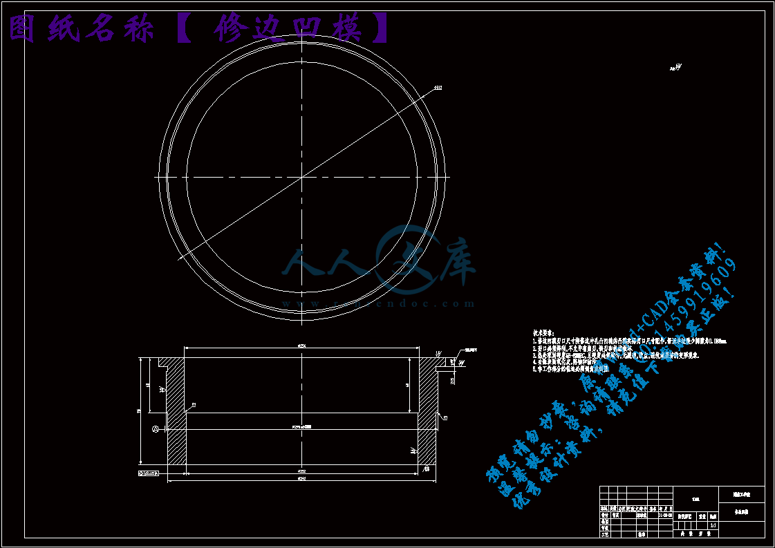
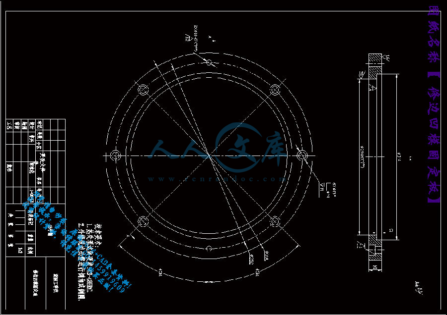
下模固定板.dwg

中期检查表.doc

任务书.doc

修边凹模.dwg

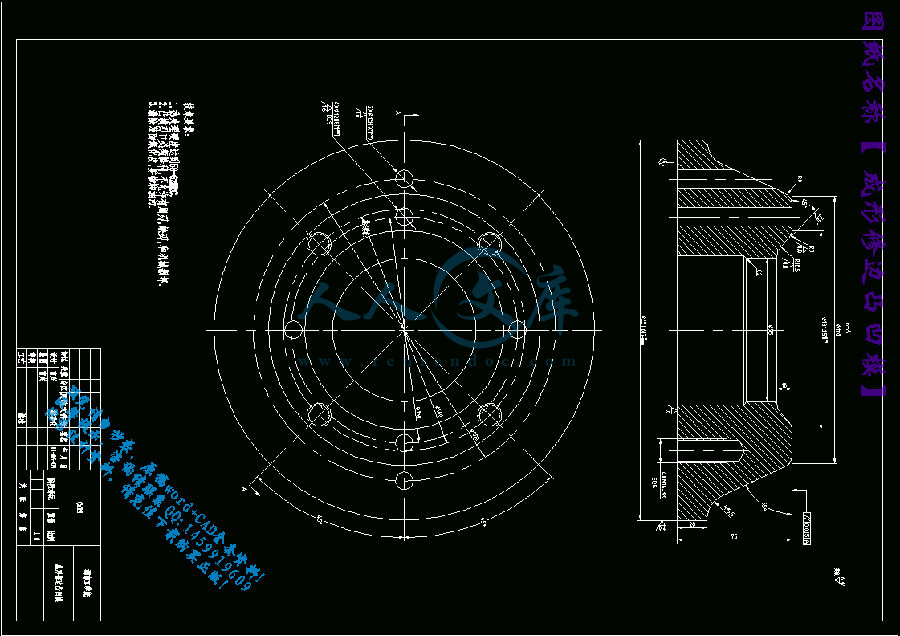
修边凹模固定板.dwg

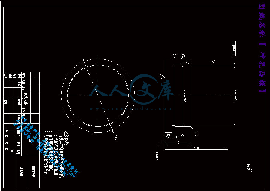
冲孔凸模.dwg

外文翻译---冲压模具设计中侧壁起皱的分析   中文版.pdf

实习报告.doc

封面.doc

开题报告.doc

御料板.dwg

成形修边凸凹模.dwg

成形冲孔凸凹模.dwg

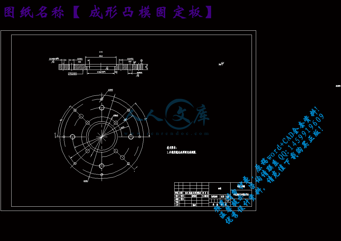
成形凸模固定板.dwg

指导教师评阅表.doc

正文.doc

答辩资格审查表.doc

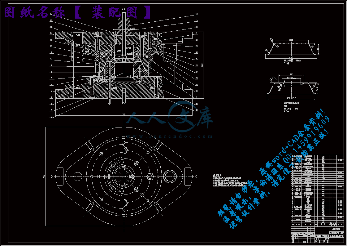
装配图.dwg

评阅评语表.doc

湖南工学院2011  届毕业设计(论文)课题任务书

系: 机械工程系                           专业: 材料成型及控制工程

指导教师郭雪娥学生姓名曹兴

课题名称离合器壳体中心大孔冲孔,成型,修边复合模设计

内容及任务

模具零件图

模具总装图一张

全部模具零件图纸(其中至少有一张电脑绘图)

所有图纸折合成0号图不得少于3张。

自选一个重要模具零件编制加工工艺路线,进行相关的计算,并编制加工工艺卡和工序卡。

设计说明书

1、资料数据充分,并标明数据出处。

2、计算过程详细、完全。

3、公式的字母含义应标明,有时还应标注公式的出处。

4、内容条理清楚,按步骤书写。

5、说明书要求有计算机打印。

拟达到的要求或技术指标1、保证规定的生产率和高质量的冲压件的同时,力求成本低、模具寿命长。

2、设计的冷冲模必须保证操作安全、方便。

3、冲模零件必须具有良好的工艺性,即制造装配容易、便于管理。

4、便于搬运、安装、紧固到冲床上并且方便、可靠。

5、保证模具强度前提下,注意外形美观,各部分比例协调。

进度安排起止日期工作内容备注

3月1日

3月2日 ~ 4月1日

4月2日 ~ 5月4日

5月5日 ~ 5月7日

5月7日 ~ 5月20日

5月21日 ~5月23日

5月24日 ~5月25日

5月26日 ~5月29日

6月1日 ~ 6月10日

选取课题及编写开题报告;

英文论文翻译;

查询相关资料,产品基本要求分析。根据CAD二维图纸对设计模型进行Pro/E三维造型;

塑件材料选择、注射机的选择、成型方法及其工艺的选择;

模具相关结构的设计;

成型零件的制造工艺分析设计;

整理设计说明书,按照学院得规范要求排版打印设计说明书;

上交毕业设计资料,评阅;

准备答辩。

主要参考资料1、《冷冲压工艺及模具设计》刘心治主编重庆大学出版社

2、《冲压工艺及模具设计》万战胜主编 铁道出版社

3、《冲模设计》 吉林人民出版社

4、《实用冲压技术》 机工出版社

5、《冷冲压及塑料成型工艺与模具设计资料》 机工出版社

6、《模具设计与制造简明手册》 冯炳尧等编 上海出版社

7、《冲压工艺模具设计实用技术》 郑家贤编 机械工业出版社

8、《实用板金冲压工艺图集》 梁炳文主编 机械工业出版社

摘  要

复合模是冷冲压模具中加工精度、效率较高的一种设备。对于需经过几道工序才能冲压完成的零件来说,应尽可能根据零件的工艺要求采用复合模加工。本文就是对离合器壳体的前道工序半成品的进一步加工时,所需的复合模设计。这套模具适合于离合器壳体的中心大孔冲孔、成形、修边加工,其后尚有几道加工工序。在对该复合模进行设计时,主要的问题是对原工序件的底部成形方式的设计,由于要保证原工序件的大致形状精度,在这里采用局部成形的方法对底部的凸起进行加工。因此,确定合适的压边力就成了起伏成形能否成功的关健。同时,成形锥形凸包时,成形凸凹模的设计也较重要。为了设计的标准化,尽可能选用了标准件,如模架,模座,压边机等。最后对模具的一个主要零件导套进行了简单的加工工艺路线的制定。本设计对于进行起伏成形模具设计有一定的参考作用。

关键词:模具设计;复合模;压延成形

ABSTRACT

Compound die is an efficient and precise provision of normal stamp die. For

the part can not finished in only one stamp working procedure,it is better machining on the compound die according to the technical demands of the part. In the thesis, designed a compound mold used to machining the half-finished clutch shell. This set of mold suits in the clutch shell punch central hole, stamp bottom convex shape, and shave fringe, after that still had several processing working procedures. When carries on the design of this compound mold, the main question is to confirm the way of stamp the  bottom convex figuration. Because it is have to guarantee the fore working procedure’s approximate shape precise, uses partial-undulate stamp in here to processing the bottom bulge. Therefore, the key role to succeed of the partial-undulate stamp is to define reasonable blank holding force. At the same time, when stamped conical convex bulge, the design of convex-concave die is also important. In order to the standardized design, has selected the standard part as far as possible. Such as die frame, die bed plates, press machine and so on. Finally, set down the machining technical procedure of sleeve, a major mold component. The design in the thesis has some referenced value for analogical calendaring molding design.

Keywords: mold design; compound die; calendaring molding

目  录

摘  要2

1  分析冲压件的工艺性7

1.1  冲裁工艺性7

1.2  成形工艺性8

2  分析计算确定工艺方案9

2.1  确定所需的冲压基本工序9

2.2  确定工序数目9

2.2.1  确定拉伸次数9

2.2.2  顶面起伏成形加工次数的确定10

2.2  确定工序顺序11

2.3  确定工序的组合11

3  主要工艺参数的计算13

3.1  计算毛尺寸13

3.2  计算冲压力15

3.2.1  起伏成形的压力计算15

3.2.2  中心冲大孔的冲裁力15

3.2.3  修边时的冲裁力16

3.2.4  冲中心大孔时的御料力16

3.2.5 外缘修边时的御料力16

3.2.6  冲孔时的推件力17

3.2.7计算压边力17

3.3  初选压力机17

3.4  计算压力中心18

3.5  计算凸凹模刃口尺寸及公差18

3.5.1  冲中孔时凸、凹模刃口尺寸计算19

3.5.2  修边凸凹模刃口尺寸计算20

3.5.3  成形凸凹模的刃口尺寸计算20

4  模具整体结构设计22

4.1 修边凹模的设计22

4.1.1 凹模的尺寸计算22

4.1.2 凹模的结构形式23

4.2冲孔凸模的设计24

4.2.1 计算24

4.2.2 凸模的结构设计25

4.3凸凹模(冲孔凸模和修边凹模)的设计26

4.4 冲模的导向装置27

4.4.1无导向冲裁27

4.4.2导板导向28

4.4.3模架的导向28

4.5定位装置31

4.5.1条料的横向定位装置:31

4.5.2.条料的纵向定位装置:32

4.6卸料装置33

4.6.1.固定卸料装置的形式33

4.6.2.固定卸料板的固定方式33

4.7推件装置的设计33

4.7.1.推件板的结构形式34

4.7.2.推件板的尺寸与公差34

4.7.3.推件板的极点位置34

4.7.4.打杆与打板的设计34

5  其它冲模零件设计35

5.1模柄的类型及选择35

5.2凸模固定板36

5.3垫板36

5.4紧固件37

5.5定位销37

6  模具的装配38

6.1复合模的装配38

6.2凸、凹模间隙的调整38

7  具体零件的工艺方案39

总结41

参考文献42

致  谢43

1  分析冲压件的工艺性

1.1  冲裁工艺性

冲裁件的工艺性是指冲裁件对冲压工艺的适应性,即冲裁件的结构形状、尺寸大小、精度等级是否符合冲裁加工的工艺要求。良好的结构工艺性应保证材料消耗少,工序数目少,模具结构简单而寿命高,产品质量稳定,操作简单等等。通常对冲裁件的工艺性影响最大的是几何形状尺寸和精度要求。对几何形状的要求是冲裁件的形状应尽可能简单、对称,最好采用圆形、矩形等规则的几何形状或由这些形状所组成,使排样时废料最少;冲裁件的凸出悬臂和凹槽的宽度不宜太小,以免凸模折断;冲裁件的外形或内形的转角出,要避免夹角出现,应以圆弧过渡,以便于模具加工,减少热处理或冲压时的在尖角处开裂的现象,同时可以防止尖角部位的刃口磨损过快而使模具寿命降低。对精度的要求是冲裁件的经济精度一般不高于IT11级,最高可达IT8~10级,冲孔比落料的精度约高一级。

该零件的形状如图1,其冲裁工艺性为:

⑴结构与尺寸:该零件结构较简单、形状对称,完全由圆弧和直线组成,没有长的悬臂和狭槽。

⑵精度:零件尺寸最大凸缘尺寸精度为IT11,高度尺寸略低于IT12,其余尺寸均为自由尺寸,中心大孔的冲孔尺寸要求不高,可以经过普通的冲裁方法加工形成。

修边时,相应的尺寸要求和冲孔时相比较高,其凸缘尺寸为IT11级精度,因此,进行模具设计时,应保证修边时所用模具的精度。另外,零件图中还对下顶面与下底面的平行度,下底面的平面度有一定要求,因此加工时最好能使外缘的修边和顶面的成形在同一付模具上进行加工,以保证相对的位置精度和形状精度,而在冲模加工方法中,复合模能在一付模具上对工件进二道或更多的工序加工,而保持被加工零件没有相对的位移,有利于得到较高精度的加工件。因此,相对来说,该零件的冲裁加工要求可以得到保证。

⑶材料:该零件材料为10号钢,屈服强度为206Mpa,此材料具有良好的结构强度和塑性,其冲裁加工性较好。

⑷生产批量:大批量生产。

根据以上分析,该零件的冲裁性较好,可以冲裁加工。

参考文献

[1] 肖景荣、姜奎华.冲压工艺学[M]. 机械工业出版社

[2] 万战胜.冲压工艺及模具设计[M].  铁道出版社

[3] 夏具谌、李志刚.中国冲模设计大典[M]. 江西科学技术出版社

[4] 实用冲压技术[M]. 机工出版社

[5] 冷冲压及塑料成型工艺与模具设计资料[M]. 机工出版社

[6] 冯炳尧.模具设计与制造简明手册[M]. 上海出版社

[7] 郑家贤.冲压工艺模具设计实用技术[M]. 机械工业出版社

[8] 梁炳文.实用板金冲压工艺图集[M]. 机械工业出版社

[9] 甘永立.几何量公差与检测[M]. 上海科学技术出版社

[10] 章跃主.机械制造专业英语[M]. 机械工业出版社

[11] 刘心治.冷冲压工艺及模具设计[M]. 重庆大学出版社

[12] 冲模设计手册[M]. 机械工业出版社

[13] 杨玉英.实用冲压工艺及模具设计手册[M]. 机械工业出版社

内容简介:
湖南工学院毕业设计(论文)工作中期检查表题目离合器壳体中心大孔冲孔,成型,修边复合膜设计学生姓名曹兴班级学号212070216专业材料成型及控制工程指导教师填写学生开题情况已开题学生调研及查阅文献情况已进行毕业设计(论文)原计划有无调整无学生是否按计划执行工作进度是学生是否能独立完成工作任务能学生的英文翻译情况较好学生每周接受指导的次数及时间3次,6小时毕业设计(论文)过程检查记录情况较好学生的工作态度在相应选项划“”认真一般较差尚存在的问题及采取的措施:主要问题:图纸存在少些错误。采取相关的消除措施:每天找老师同学改正。指导教师签字: 年 月 日系部意见: 负责人签字:年 月 日附录1 外文译文 冲压变形冲压变形工艺可完成多种工序,其基本工序可分为分离工序和变形工序两大类。分离工序是使坯料的一部分与另一部分相互分离的工艺方法,主要有落料、冲孔、切边、剖切、修整等。其中有以冲孔、落料应用最广。变形工序是使坯料的一部分相对另一部分产生位移而不破裂的工艺方法,主要有拉深、弯曲、局部成形、胀形、翻边、缩径、校形、旋压等。从本质上看,冲压成形就是毛坯的变形区在外力的作用下产生相应的塑性变形,所以变形区的应力状态和变形性质是决定冲压成形性质的基本因素。因此,根据变形区应力状态和变形特点进行的冲压成形分类,可以把成形性质相同的成形方法概括成同一个类型并进行系统化的研究。绝大多数冲压成形时毛坯变形区均处于平面应力状态。通常认为在板材表面上不受外力的作用,即使有外力作用,其数值也是较小的,所以可以认为垂直于板面方向的应力为零,使板材毛坯产生塑性变形的是作用于板面方向上相互垂直的两个主应力。由于板厚较小,通常都近似地认为这两个主应力在厚度方向上是均匀分布的。基于这样的分析,可以把各种形式冲压成形中的毛坯变形区的受力状态与变形特点,在平面应力的应力坐标系中(冲压应力图)与相应的两向应变坐标系中(冲压应变图)以应力与应变坐标决定的位置来表示。也就是说,冲压应力图与冲压应变图中的不同位置都代表着不同的受力情况与变形特点 (1)冲压毛坯变形区受两向拉应力作用时,可以分为两种情况:即0t=0和 0,t=0。再这两种情况下,绝对值最大的应力都是拉应力。以下对这两种情况进行分析。1)当0且t=0时,安全量理论可以写出如下应力与应变的关系式:(1-1) /(-m)=/(-m)=t/(t -m)=k 式中 ,t分别是轴对称冲压成形时的径向主应变、切向主应变和厚度方向上的主应变;,t分别是轴对称冲压成形时的径向主应力、切向主应力和厚度方向上的主应力;m平均应力,m=(+t)/3; k常数。在平面应力状态,式(11)具有如下形式:3/(2-)=3/(2-t)=3t/-(t+)=k (12)因为0,所以必定有2-0与0。这个结果表明:在两向拉应力的平面应力状态时,如果绝对值最大拉应力是,则在这个方向上的主应变一定是正应变,即是伸长变形。又因为0,所以必定有-(t+)0与t2时,0;当 0。 的变化范围是 =0 。在双向等拉力状态时,= ,有式(12)得 =0 及 t 0且t=0时,有式(12)可知:因为 0,所以1) 定有2 0与0。这个结果表明:对于两向拉应力的平面应力状态,当的绝对值最大时,则在这个方向上的应变一定时正的,即一定是伸长变形。又因为0,所以必定有-(t+)0与t,0;当 0。的变化范围是 = =0 。当= 时,=0,也就是在双向等拉力状态下,在两个拉应力方向上产生数值相同的伸长变形;在受单向拉应力状态时,当=0时,=- /2,也就是说,在受单向拉应力状态下其变形性质与一般的简单拉伸是完全一样的。这种变形与受力情况,处于冲压应变图中的AOC范围内(见图11);而在冲压应力图中则处于AOH范围内(见图12)。上述两种冲压情况,仅在最大应力的方向上不同,而两个应力的性质以及它们引起的变形都是一样的。因此,对于各向同性的均质材料,这两种变形是完全相同的。(1)冲压毛坯变形区受两向压应力的作用,这种变形也分两种情况分析,即t=0和 0,t=0。 1)当0且t=0时,有式(12)可知:因为0,一定有2-0与0。这个结果表明:在两向压应力的平面应力状态时,如果绝对值最大拉应力是0,则在这个方向上的主应变一定是负应变,即是压缩变形。又因为0与t0,即在板料厚度方向上的应变是正的,板料增厚。在方向上的变形取决于与的数值:当=2时,=0;当2时,0;当 0。这时 的变化范围是 与0之间 。当=时,是双向等压力状态时,故有 =0;当=0时,是受单向压应力状态,所以=-/2。这种变形情况处于冲压应变图中的EOG范围内(见图11);而在冲压应力图中则处于COD范围内(见图12)。2) 当 0且t=0时,有式(12)可知:因为 0,所以一定有2 0与0。这个结果表明:对于两向压应力的平面应力状态,如果绝对值最大是,则在这个方向上的应变一定时负的,即一定是压缩变形。又因为0与t0,即在板料厚度方向上的应变是正的,即为压缩变形,板厚增大。在方向上的变形取决于与的数值:当=2时,=0;当2,0;当 0。这时,的数值只能在= =0 之间变化。当= 时,是双向等压力状态,所以=0。这种变形与受力情况,处于冲压应变图中的GOL范围内(见图11);而在冲压应力图中则处于DOE范围内(见图12)。(1)冲压毛坯变形区受两个异号应力的作用,而且拉应力的绝对值大于压应力的绝对值。这种变形共有两种情况,分别作如下分析。1)当0,|时,由式(12)可知:因为0,|,所以一定有2-0及0。这个结果表明:在异号的平面应力状态时,如果绝对值最大应力是拉应力,则在这个绝对值最大的拉应力方向上应变一定是正应变,即是伸长变形。 又因为0,|,所以必定有00,0, |时,由式(12)可知:用与前项相同的方法分析可得0。即在异号应力作用的平面应力状态下,如果绝对值最大应力是拉应力,则在这个方向上的应变是正的,是伸长变形;而在压应力方向上的应变是负的(0, 0, 0,|时,由式(12)可知:因为0,|,所以一定有2- 0及0,0,必定有2- 0,即在拉应力方向上的应变是正的,是伸长变形。这时的变化范围只能在=-与=0的范围内 。当=-时,00,0, |时,由式(12)可知:用与前项相同的方法分析可得0, 0, 0,0 AONGOH+ +伸长类AOCAOH+ +伸长类双向受压0,0 EOGCOD 压缩类0,|MONFOG+ +伸长类|LOMEOF 压缩类异号应力0,|CODAOB+ +伸长类| |DOEBOC 压缩类表11 冲压应力状态与冲压变形状态的对照表12 伸长类成形与压缩类成形的对比项目伸长类成形压缩类成形变形区质量问题的表现形式变形程度过大引起变形区产生破裂现象压力作用下失稳起皱成形极限1 主要取决于板材的塑性,与厚度无关2 可用伸长率及成形极限DLF判断1 主要取决于传力区的承载能力2 取决于抗失稳能力3 与板厚有关变形区板厚的变化减薄增厚提高成形极限的方法1 改善板材塑性2 使变形均匀化,降低局部变形程度3 工序间热处理1 采用多道工序成形2 改变传力区与变形区的力学关系3 采用防起皱措施图13 冲压应变图图 13 体系化研究方法举例附录2 外文原文Categories of stamping formingMany deformation processes can be done by stamping, the basic processes of the stamping can be divided into two kinds: cutting and forming.Cutting is a shearing process that one part of the blank is cut form the other .It mainly includes blanking, punching, trimming, parting and shaving, where punching and blanking are the most widely used. Forming is a process that one part of the blank has some displacement form the other. It mainly includes deep drawing, bending, local forming, bulging, flanging, necking, sizing and spinning.In substance, stamping forming is such that the plastic deformation occurs in the deformation zone of the stamping blank caused by the external force. The stress state and deformation characteristic of the deformation zone are the basic factors to decide the properties of the stamping forming. Based on the stress state and deformation characteristics of the deformation zone, the forming methods can be divided into several categories with the same forming properties and to be studied systematically.The deformation zone in almost all types of stamping forming is in the plane stress state. Usually there is no force or only small force applied on the blank surface. When it is assumed that the stress perpendicular to the blank surface equal to zero, two principal stresses perpendicular to each other and act on the blank surface produce the plastic deformation of the material. Due to the small thickness of the blank, it is assumed approximately that the two principal stresses distribute uniformly along the thickness direction. Based on this analysis, the stress state and the deformation characteristics of the deformation zone in all kind of stamping forming can be denoted by the point in the coordinates of the plane principal stress(diagram of the stamping stress) and the coordinates of the corresponding plane principal stains (diagram of the stamping strain). The different points in the figures of the stamping stress and strain possess different stress state and deformation characteristics.(1)When the deformation zone of the stamping blank is subjected toplanetensile stresses, it can be divided into two cases, that is 0,t=0and 0,t=0.In both cases, the stress with the maximum absolute value is always a tensile stress. These two cases are analyzed respectively as follows.2)In the case that 0andt=0, according to the integral theory, the relationships between stresses and strains are: /(-m)=/(-m)=t/(t -m)=k 1.1where, ,t are the principal strains of the radial, tangential and thickness directions of the axial symmetrical stamping forming; ,and tare the principal stresses of the radial, tangential and thickness directions of the axial symmetrical stamping forming;m is the average stress,m=(+t)/3; k is a constant.In plane stress state, Equation 1.1 3/(2-)=3/(2-t)=3t/-(t+)=k 1.2Since 0,so 2-0 and 0.It indicates that in plane stress state with two axial tensile stresses, if the tensile stress with the maximum absolute value is , the principal strain in this direction must be positive, that is, the deformation belongs to tensile forming.In addition, because 0,therefore -(t+)0 and t2,0;and when 0.The range of is =0 . In the equibiaxial tensile stress state = ,according to Equation 1.2,=0 and t 0 and t=0, according to Equation 1.2 , 2 0 and 0,This result shows that for the plane stress state with two tensile stresses, when the absoluste value of is the strain in this direction must be positive, that is, it must be in the state of tensile forming.Also because0,therefore -(t+)0 and t,0;and when 0.The range of is = =0 .When =,=0, that is, in equibiaxial tensile stress state, the tensile deformation with the same values occurs in the two tensile stress directions; when =0, =- /2, that is, in uniaxial tensile stress state, the deformation characteristic in this case is the same as that of the ordinary uniaxial tensile.This kind of deformation is in the region AON of the diagram of the stamping strain (see Fig.1.1), and in the region GOH of the diagram of the stamping stress (see Fig.1.2). Between above two cases of stamping deformation, the properties ofand, and the deformation caused by them are the same, only the direction of the maximum stress is different. These two deformations are same for isotropic homogeneous material.(1)When the deformation zone of stamping blank is subjected to two compressive stressesand(t=0), it can also be divided into two cases, which are 0,t=0 and 0,t=0. 1)When 0 and t=0, according to Equation 1.2, 2-0与=0.This result shows that in the plane stress state with two compressive stresses, if the stress with the maximum absolute value is 0, the strain in this direction must be negative, that is, in the state of compressive forming.Also because 0 and t0.The strain in the thickness direction of the blankt is positive, and the thickness increases.The deformation condition in the tangential direction depends on the values of and .When =2,=0;when 2,0;and when 0.The range of is 0.When =,it is in equibiaxial tensile stress state, hence=0; when =0,it is in uniaxial tensile stress state, hence =-/2.This kind of deformation condition is in the region EOG of the diagram of the stamping strain (see Fig.1.1), and in the region COD of the diagram of the stamping stress (see Fig.1.2).2)When 0and t=0, according to Equation 1.2,2- 0 and 0. This result shows that in the plane stress state with two compressive stresses, if the stress with the maximum absolute value is , the strain in this direction must be negative, that is, in the state of compressive forming.Also because 0 and t0.The strain in the thickness direction of the blankt is positive, and the thickness increases.The deformation condition in the radial direction depends on the values of and . When =2, =0; when 2,0; and when 0.The range of is = =0 . When = , it is in equibiaxial tensile stress state, hence =0.This kind of deformation is in the region GOL of the diagram of the stamping strain (see Fig.1.1), and in the region DOE of the diagram of the stamping stress (see Fig.1.2).(3) The deformation zone of the stamping blank is subjected to two stresses with opposite signs, and the absolute value of the tensile stress is larger than that of the compressive stress. There exist two cases to be analyzed as follow: 1)When 0, |, according to Equation 1.2, 2-0 and 0.This result shows that in the plane stress state with opposite signs, if the stress with the maximum absolute value is tensile, the strain in the maximum stress direction is positive, that is, in the state of tensile forming.Also because 0, |, therefore =-. When =-, then 0,0,0, |, according to Equation 1.2, bymeans of the same analysis mentioned above, 0, that is, the deformation zone is in the plane stress state with opposite signs. If the stress with the maximum absolute value is tensile stress , the strain in this direction is positive, that is, in the state of tensile forming. The strain in the radial direction is negative (=-. When =-, then 0, 0, 0,|, according to Equation 1.2, 2- 0 and 0 and 0, therefore 2- 0. The strain in the tensile stress direction is positive, or in the state of tensile forming.The range of is 0=-.When =-, then 0,0,0, |, according to Equation 1.2 and by means of the same analysis mentioned above,=-.When =-, then 0, 0, 0,0 AONGOH+ +TensileAOCAOH+ +TensileBiaxial compressive stress state0,0 EOGCOD Compressive0,| MONFOG+ +Tensile|LOMEOF CompressiveState of stress with opposite signs0,|CODAOB+ +Tensile| |DOEBOC CompressiveTable 1.1 Comparison between states of stress and strain in stamping Table 1.2 Comparison between tensile and compressive formingItem Tensile forming Compressive formingRepresentation of the quality problem in the deformation zoneFracture in the deformation zone due to excessive deformationInstability wrinkle caused by compressive stressForming limit3 Mainly depends on the plasticity of the material, and is irrelevant to the thickness4 Can be estimated by extensibility or the forming limit DLF4 Mainly depends on the loading capability in the force transferring zone 5 Depends on the anti-instability capability6 Has certain relationship to the blank thicknessVariation of the blank thickness in the deformation zone Thinning ThickeningMethods to improve forming limit4 Improve the plasticity of the material5 Decrease local deformation, and increase deformation uniformity6 Adopt an intermediate heat treatment process4 Adopt multi-pass forming process 5 Change the mechanics relationship between the force transferring and deformation zones6 Adopt anti-wrinkle measuresFig.1.1 Diagram of stamping strain Fig.1.2 Diagram of stamping stress Fig.1.3 Examples for systematic research methods湖南工学院2011 届毕业设计(论文)课题任务书系: 机械工程系 专业: 材料成型及控制工程指导教师郭雪娥学生姓名曹兴课题名称离合器壳体中心大孔冲孔,成型,修边复合模设计内容及任务模具零件图模具总装图一张全部模具零件图纸(其中至少有一张电脑绘图)所有图纸折合成0号图不得少于3张。自选一个重要模具零件编制加工工艺路线,进行相关的计算,并编制加工工艺卡和工序卡。设计说明书1、资料数据充分,并标明数据出处。2、计算过程详细、完全。3、公式的字母含义应标明,有时还应标注公式的出处。4、内容条理清楚,按步骤书写。5、说明书要求有计算机打印。拟达到的要求或技术指标1、保证规定的生产率和高质量的冲压件的同时,力求成本低、模具寿命长。2、设计的冷冲模必须保证操作安全、方便。3、冲模零件必须具有良好的工艺性,即制造装配容易、便于管理。4、便于搬运、安装、紧固到冲床上并且方便、可靠。5、保证模具强度前提下,注意外形美观,各部分比例协调。进度安排起止日期工作内容备注3月1日3月2日 4月1日4月2日 5月4日5月5日 5月7日5月7日 5月20日5月21日 5月23日5月24日 5月25日5月26日 5月29日6月1日 6月10日 选取课题及编写开题报告;英文论文翻译;查询相关资料,产品基本要求分析。根据CAD二维图纸对设计模型进行Pro/E三维造型;塑件材料选择、注射机的选择、成型方法及其工艺的选择;模具相关结构的设计;成型零件的制造工艺分析设计;整理设计说明书,按照学院得规范要求排版打印设计说明书;上交毕业设计资料,评阅;准备答辩。主要参考资料、冷冲压工艺及模具设计刘心治主编重庆大学出版社、冲压工艺及模具设计万战胜主编 铁道出版社、冲模设计 吉林人民出版社、实用冲压技术 机工出版社、冷冲压及塑料成型工艺与模具设计资料 机工出版社、模具设计与制造简明手册 冯炳尧等编 上海出版社7、冲压工艺模具设计实用技术郑家贤编机械工业出版社8、实用板金冲压工艺图集梁炳文主编机械工业出版社教研室意见年 月 日系主管领导意见年 月 日实习报告毕业实习结束了,总体感觉是这次我们很好地完成了实习内容,达到了实习的目的。这次实习的针对性特别强,为我们进一步巩固了基础知识,让我们看到理论到实践的转变,了解了一个公司是如何从研发到生产再到销售,更重要的是为下一步的毕业设计打下了很好的基础。这次实习是大学期间最后一次实习了,回想以前,经历了大大小小很多次实习,可每次实习都会上升一个层次去思考,同样去一个地方,所思考的问题更深了;同样看一个设备所关注的东西更专业化。因此每次实习的收获都是不一样的。记得第一次实习跟着带队老师从前走到后,看到的是没有见过的巨大的设备,心里只有感慨、好奇和新鲜的感觉。后来陆续又参加了金工实习、生产实习,再次进到厂里时,还是看的同样的设备却没有了好奇没有了感慨,取而代之的是思考和请教,思考车间设备生产的工艺流程,思考每一种工艺的原理,请教工人师傅不懂的问题,再也不象以前那样走马观花,看问题也看得更加深了。这次是毕业设计实习,首先感到的是机会的难能可贵,想在走上社会走进工厂之前多积累一些经验。进厂后抓紧每一分钟尽量多的了解自己要设计的产品,有一种急切的求知欲。在到达自己将要设计的模具或产品时,同学们都努力的去理解相关模具的工作原理,和自己设计部分的结构。有相机的绕着设备拍几张照片回去作为参考,没有的在现场做做记录。总之,这次的实习看到了大四同学成熟了许多,不再有刚来时的幼稚,更多一些的是对走上工作岗位的向往。最后,在这次实习中,真诚地感谢带我们实习的任学平老师。 2011届毕业论文 离合器壳体中心大孔冲孔,成型,修边复合模设计系 、 部: 机械工程系 学生姓名: 曹兴 指导教师: 黄继承 职称 讲师 专 业: 材料成型及控制工程 班 级: 0702班 完成时间: 2011年5月28号 3摘 要复合模是冷冲压模具中加工精度、效率较高的一种设备。对于需经过几道工序才能冲压完成的零件来说,应尽可能根据零件的工艺要求采用复合模加工。本文就是对离合器壳体的前道工序半成品的进一步加工时,所需的复合模设计。这套模具适合于离合器壳体的中心大孔冲孔、成形、修边加工,其后尚有几道加工工序。在对该复合模进行设计时,主要的问题是对原工序件的底部成形方式的设计,由于要保证原工序件的大致形状精度,在这里采用局部成形的方法对底部的凸起进行加工。因此,确定合适的压边力就成了起伏成形能否成功
温馨提示:
1: 本站所有资源如无特殊说明,都需要本地电脑安装OFFICE2007和PDF阅读器。图纸软件为CAD,CAXA,PROE,UG,SolidWorks等.压缩文件请下载最新的WinRAR软件解压。
2: 本站的文档不包含任何第三方提供的附件图纸等,如果需要附件,请联系上传者。文件的所有权益归上传用户所有。
3.本站RAR压缩包中若带图纸,网页内容里面会有图纸预览,若没有图纸预览就没有图纸。
4. 未经权益所有人同意不得将文件中的内容挪作商业或盈利用途。
5. 人人文库网仅提供信息存储空间,仅对用户上传内容的表现方式做保护处理,对用户上传分享的文档内容本身不做任何修改或编辑,并不能对任何下载内容负责。
6. 下载文件中如有侵权或不适当内容,请与我们联系,我们立即纠正。
7. 本站不保证下载资源的准确性、安全性和完整性, 同时也不承担用户因使用这些下载资源对自己和他人造成任何形式的伤害或损失。
提示  人人文库网所有资源均是用户自行上传分享,仅供网友学习交流,未经上传用户书面授权,请勿作他用。
关于本文
本文标题:离合器壳体中心大孔冲孔、成型、修边复合模设计【优秀】【word+9张CAD图纸全套】【冲压复合模具类】【毕设】
链接地址:https://www.renrendoc.com/p-298492.html

官方联系方式

2:不支持迅雷下载,请使用浏览器下载   
3:不支持QQ浏览器下载,请用其他浏览器   
4:下载后的文档和图纸-无水印   
5:文档经过压缩,下载后原文更清晰   
关于我们 - 网站声明 - 网站地图 - 资源地图 - 友情链接 - 网站客服 - 联系我们

网站客服QQ:2881952447     

copyright@ 2020-2025  renrendoc.com 人人文库版权所有   联系电话:400-852-1180

备案号:蜀ICP备2022000484号-2       经营许可证: 川B2-20220663       公网安备川公网安备: 51019002004831号

本站为文档C2C交易模式,即用户上传的文档直接被用户下载,本站只是中间服务平台,本站所有文档下载所得的收益归上传人(含作者)所有。人人文库网仅提供信息存储空间,仅对用户上传内容的表现方式做保护处理,对上载内容本身不做任何修改或编辑。若文档所含内容侵犯了您的版权或隐私,请立即通知人人文库网,我们立即给予删除!