题目申报表.doc

点胶机的点胶部分的机械结构设计【优秀】【word+4张CAD图纸全套】【毕设】

收藏

资源目录
跳过导航链接。
压缩包内文档预览:
预览图 预览图
编号:304813    类型:共享资源    大小:8.21MB    格式:RAR    上传时间:2014-08-07 上传人:QQ14****9609 IP属地:陕西
15
积分
关 键 词:
点胶机 部分 部份 机械 结构设计 优秀 优良 word cad 图纸 全套
资源描述:

点胶机械手的结构设计

点胶机的点胶部分的机械结构设计【优秀】【word+4张CAD图纸全套】【毕业设计】

【带开题报告+评阅人意见表+实习报告+题目申报表+外文翻译】【39页@正文11600字】【详情如下】【需要咨询购买全套设计请加QQ1459919609】

Study of precision micro-holes in borosilicate glass using micro EDM combined with micro ultrasonic vibration machining.pdf

中期自查表.doc

前期材料.doc

实习报告.doc

封面.doc

工程图12.DWG

工程图13.DWG

工程图14.DWG

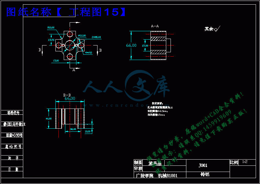
工程图15.DWG

开题报告.doc

指导教师审阅意见表.doc

正文.doc

目     录.doc

答辩结果表.doc

翻译.doc

评阅人意见表.doc

题目申报表.doc

题目申报表

设计(论文)题 目  点胶机的点胶部分的机械结构的设计

题目简介:

    点胶机又称涂胶机、滴胶机、打胶机、灌胶机等,专门对流体进行控制。并将流体点滴、涂覆于产品表面或产品内部的自动化机器,可实现三维、四维路径点胶,精确定位,精准控胶,不拉丝,不漏胶,不滴胶。点胶机主要用于产品工艺中的胶水、油漆以及其他液体精确点、注、涂、点滴到每个产品精确位置,可以用来实现打点、画线、圆型或弧型。

现在根据用户的需求,对AB胶水进行点胶机械手的设计,根据胶水的性质,我们选择丝杆推胶,于是我进行大体设计,确定标准件的种类,非标准件材料的选择,于是再进行非标准件的设计,画出二维图纸,进行受力计算,确定标准件的具体型号。对于无法确定的尺寸,而我们把三维图形画出来,并且装配好之后再量取数据。对于一些设计不合理的零件,我们边设计边修改。

审核意见:

审核人签名:

年     月      日

题目类型--1、为结合科研;2、为结合生产实际;3、为结合大学生科研训练计划; 

4、为结合学科竞赛;5、模拟仿真;6、其它

题目来源--A.指导教师出题 ; B.学生自定、自拟

开题报告

设计(论文)题 目点胶机的点胶部分的机械结构的设计

开题报告内容:(调研资料的准备与总结,研究目的、要求、思路与预期成果;任务完成的阶段、 内容及时间安排;完成毕业设计(论文)所具备的条件因素等。)

本毕业设计(论文)课题应达到的目的:

(1)培养学生的调查研究以及资料、信息的获取、分析等综合能力;

(2)培养学生的工程设计能力,主要包括设计、计算及绘图能力;

(3)培养学生的综合运用专业理论知识,分析解决实际问题的能力;

(4)培养学生的在设计过程中使用计算机的能力;

(5)培养学生的撰写设计说明书、论文的能力;

(6)培养学生创新能力和创新精神。

本毕业设计(论文)课题工作进度计划:

起止日期工 作 内 容

2014-02-22~2014-03-31

2014-04-1~2014-05-30

2014-06-01~2014-06-07

毕业设计开始,查阅中外文资料,完成外文翻译,完成实习调研和实习报告,完成开题报告;进行毕业设计,熟悉CAD、solidworks等画图软件接收毕业设计中期检查,根据设计要求,进行机械结构原理设计和结构设计,撰写毕业设计论文;修改完善毕业论文、准备毕业答辩、整理毕业设计期间的所有资料、成果并归档。

文 献 综 述

a)引言

随着科技的不断进步,一些电子产品体型也来越小,而人们对产品大功能的期望却丝毫不减,于是我们得进入微型化加工安装时代。IPhone一家喻户晓的手机,其做工精细,对外形的胶合要求较高,胶合轨迹复杂,人工难以实现其高要求,必定用机器来代替,涂抹胶水的点胶机就需求量不断上升。

  二、点胶机机械工作原理

利用松下伺服马达带动丝杆旋转推动挤压快来挤出胶水,同时利用电子气压阀开关来控制胶水口的开关。准备点胶的时候工作台处于初始状态,点胶开始的时候x、y同时运动到指定位置,于是z轴开始运动,将点针运动到待点胶处,胶口开关开启,于是边点胶,工作平台边移动,胶水均匀分不到指定位置,点胶完成,胶水A、B混合后点胶时,可同时挤出两种胶水,并且在螺旋点胶头里面混合均匀再点胶,开关胶水是利用高压气体带动气缸上下运动实现同时拖动点胶阀开闭。

   三、点胶机的特点

结合了计算机控制和点胶两门技术。内设伺服闭环控制系统,优点:点胶轨迹是利用C语言编程的,应用点胶复杂轨迹的小型零件,每个自由度上配备有一个伺服器因此其运动轨迹比较精准,分辨率:0.001mm,可以以直线、圆弧等复杂轨迹运动。滴胶精度比较高,可达0.02克/滴,利用激光对刀,精确度高,可替代人工作业,实现机械化生产;单机即可操作,简单便利、高速精确;SD卡存储方式,方便资料管理及机台间文件传输;可搭载双组分泵送系统,构成双液全自动点胶机;可加装点胶控制器及点胶阀等配件构成落地式点胶设备;可搭载螺丝锁付机构,配置成自动锁螺丝机;可按需升级为在线机器人,用于各种自动化装配;承载能力强、加工空间大。

四、点胶机的发展概况

      点胶机又称涂胶机、滴胶机、打胶机等,是专门对流体进行控制,并将流体点滴、涂覆于产品表面或产品内部的自动化机器。点胶机主要用于产品工艺中的胶水、油漆以及其他液体精确点、注、涂、点滴到每个产品精确位置,可以用来实现打点、画线、圆型或弧型。

 精度要求还是有很大差距。双组份的点胶机目前国外的机器挺多,技术也相对成熟,只是价位太高。

    国内双液点胶技术已经走向成熟,国内双液点胶机知名品牌深圳德信、胜翔自动化、

腾洲自动化、深圳世椿(SECOND-AUTO)、东莞赛恩斯(SES)、益达Y&D、欧宝(Oupel)、特盈(TWINWIN)、腾盛(TENSUN)、axxon轴心自控目前已经有专业双液设备存在,而且质量稳定,价格合适,很适合国内用户使用。

 随着电子胶水的普遍应用,点胶设备的应用也会更加广泛和多样化。目前,单组份的点胶技术相对成熟,其发展方向是自动化和高精度。

  五、点胶机的难点

 点胶机最常遇到的问题是阀门问题,下列为解决胶阀使用时经常发生的问题的有效方法。

 胶阀滴漏此种情形经常发生予胶阀关毕以后。95%的此种情形是因为使用的针头口径太小所致。

  太小的针头会影响液体的流动造成背压, 结果导致胶阀关毕后不久形成滴漏的现象。过小的针头也会影响胶阀开始使用时的排气泡动作.只要更换较大的针头即可解决这种问题。锥形斜式针头产生的背压最少, 液体流动最顺畅。液体内空气在胶阀关毕后会产生滴漏现象, 最好是预先排除液体内空气,或改用不容易含气泡的胶.或先将胶离心脱泡后在使用。

 出胶大小不一致

 当出胶不一致时主要为储存流体的压力筒或空气压力不稳定所产生。

  进气压力调压表应设定于比厂内最低压力低10至15psi.,压力筒使用的压力应介于调压表中间以上的压力, 应避免使用压力介于压力表之中低压力部分。

 胶阀控制压力应至少60psi以上以确保出胶稳定。

 最后应检查出胶时间.若小于15/1000秒会造成出胶不稳定.,出胶时间愈长出胶愈稳定。

 流速太慢

 流速若太慢应将管路从1/4” 改为3/8”。

 管路若无需要应愈短愈好。

 除了改管子,还要改出胶口和气压,这样完全加快流速。

 流体内的气泡

 过大的流体压力若加上过短的开阀时间则有可能将空气渗入液体内. 解决方法为降低流体压力并使用锥形斜式针头。

胶水堵塞

此种情形主要因过多的湿气或重复使用过的瞬间胶。应确保使用新鲜的瞬间胶。将管路以未含湿气的Aceton丙酮彻底清洗过。使用的空气应确定完干燥且于厂内空压与胶阀系统间加装过滤器。(以上方法如仍然无效,则应使用氮气) 。

七、研究手段

根据机械设计、机械原理、工程力学、尺寸公差、工程材料,利用CAD、solidworks辅助设计,大体原理设计、具体零件设计、样品安装检验、修改完善、样品安装检验直至完善样品、再根据经验实现设计,大批量生产。。.

本课题要研究或解决的问题和拟采用的研究手段(途径)

主要研究内容:

2、两自由度风洞实验运动装置机械结构的构型选择;

3、两自由度风洞实验运动装置机械结构的转动运动分析;

4、两自由度风洞实验运动装置机械结构的完整机械系统;

5、两自由度风洞实验运动装置机械结构的力学分析;

6、根据分析结果采用ADAMS软件对两自由度风洞实验运动装置机械结构进行优化。

研究工作步骤:

1、查阅相关的文献资料,熟悉和掌握机构理论和方法,清晰设计思路;

2、根据设计要求,进行探针标定装置原理设计和结构设计;

3、采用ADAMS软件进行运动学和动力学分析优化;

4、整理资料,准备写设计说明书。

5、完善毕业论文,准备答辩。

中文摘要

点胶机又称涂胶机、滴胶机、打胶机、灌胶机等,专门对流体进行控制。并将流体点滴、涂覆于产品表面或产品内部的自动化机器,可实现三维、四维路径点胶,精确定位,精准控胶,不拉丝,不漏胶,不滴胶。点胶机主要用于产品工艺中的胶水、油漆以及其他液体精确点、注、涂、点滴到每个产品精确位置,可以用来实现打点、画线、圆型或弧型。

现在根据用户的需求,对AB胶水进行点胶机械手的设计,根据胶水的性质,我们选择丝杆推胶,于是我进行大体设计,确定标准件的种类,非标准件材料的选择,于是再进行非标准件的设计,画出二维图纸,进行受力计算,确定标准件的具体型号。对于无法确定的尺寸,而我们把三维图形画出来,并且装配好之后再量取数据。对于一些设计不合理的零件,我们边设计边修改。

ABSTRACT

Also known as glue dispenser machine, dispensing machine, plastic machine, plastic irrigation machines, specialized fluid control.And a fluid drip, coated on the interior surface of the product or product automation machines, enabling three-dimensional, four-dimensional path dispensing, accurate positioning, precise control of glue, not drawing, not leak glue,no epoxy.Dispensing technology products are mainly used in glues, paints and other liquid precise point, injection, coating, drip into the precise location of each product can be used to achieve the RBI, drawing a line, circle or arc.

Now according to the user's needs, AB glue dispensing robot be designed according to the nature of glue, we chose to push plastic screw, so I carried out the general design, determine the type of standard parts, non-standard pieces of material choice, so then non-standard design, draw two-dimensional drawings, conducted by the force calculations to determine the specific type of standard parts.For unable to determine the size, but we have drawn three-dimensional graphics, and the amount of data after re-assembled. For some poorly designed parts, we edge to edge design modifications.中文摘要

ABSTRACT

目     录

第一章 绪论  ……………………………………………………………………1

1.1点胶机特点 ……………………………………………………………………1

1.2 工作原理 ………………………………………………………………………1

1.3 常见问题 ………………………………………………………………………1

1.4 厂商需点胶水类型 ……………………………………………………………3

1.5 厂商胶量要求 …………………………………………………………………3


第二章 点胶机械手零件的设计 …………………………………………………4

2.1 概念设计 ………………………………………………………………………4

2.1.1 点胶方式选择 ………………………………………………………………4

2.1.2 模型设计 ……………………………………………………………………4

2.1.3 标准件的名称确定 …………………………………………………………4

2.2 实体设计 ………………………………………………………………………5

2.2.1 胶管夹具设计 ………………………………………………………………5

2.2.2 混合胶管的选择 ……………………………………………………………7

2.2.3 气缸的选择 …………………………………………………………………8

2.2.4 气缸与Y型点胶阀连接件的设计 …………………………………………9

2.2.5 点胶气缸固定基座的设计  ………………………………………………10

2.2.6 点胶旋转片的设计…………………………………………………………11

2.2.7点胶蝇嘴固定座的设计……………………………………………………12

2.2.8 点胶安装板的设计…………………………………………………………13

2.2.9 滚珠丝杆的选择……………………………………………………………14

2.2.10 导柱的设计 ………………………………………………………………19

2.2.11 导套的设计 ………………………………………………………………20

2.2.12 代号为J004的零件是设计………………………………………………20

2.2.13 锁紧座的设计 ……………………………………………………………21

2.2.14 代号为J001的零件是设计………………………………………………22

2.2.15 推杆的设计 ………………………………………………………………23

2.2.16 推胶头的设计 ……………………………………………………………24

2.2.17 代号为J006的零件的设计  ……………………………………………25

2.2.18代号为J005的零件的设计 ………………………………………………26

2.2.19代号为J007的零件的设计 ………………………………………………27

2.2.20  滑板的设计………………………………………………………………27

2.2.21 电机的选择 ………………………………………………………………28

2.2.22 联轴器的选择 ……………………………………………………………29

第三章 实体图片…………………………………………………………………32

第四章 总结………………………………………………………………………34

参考文献……………………………………………………………………………35

第一章 绪论

点胶机又称涂胶机、滴胶机、打胶机、灌胶机等,专门对流体进行控制。并将流体点滴、涂覆于产品表面或产品内部的自动化机器,可实现三维、四维路径点胶,精确定位,精准控胶,不拉丝,不漏胶,不滴胶。点胶机主要用于产品工艺中的胶水、油漆以及其他液体精确点、注、涂、点滴到每个产品精确位置,可以用来实现打点、画线、圆型或弧型。

如今根据市场特定的需求,改进现有点胶机,用于专业的不同的胶水点胶。

1.1点胶机特点

可替代人工作业,实现机械化生产;单机即可操作,简单便利、高速精确;SD卡存储方式,方便资料管理及机台间文件传输;可搭载双组分泵送系统,构成双液全自动点胶机;可加装点胶控制器及点胶阀等配件构成落地式点胶设备;可搭载螺丝锁付机构,配置成自动锁螺丝机;可按需升级为在线机器人,用于各种自动化装配;承载能力强、加工空间大。

1.2工作原理

伺服电机带动螺杆转动推进各活塞,将胶压进与活塞室相连的进给管中,当活塞处于上冲程时不挤胶,当活塞向下推进滴胶针头时,胶从针嘴压出。滴出的胶量由活塞下冲的距离决定,可以手工调节,也可以在软件中自动控制。

1.3常见问题

点胶机最常遇到的问题是阀门问题,下列为解决胶阀使用时经常发生的问题的有效方法。

胶阀滴漏此种情形经常发生予胶阀关毕以后。95%的此种情形是因为使用的针头口径太小所致。

太小的针头会影响液体的流动造成背压, 结果导致胶阀关毕后不久形成滴漏的现象。过小的针头也会影响胶阀开始使用时的排气泡动作.只要更换较大的针头即可解决这种问题。锥形斜式针头产生的背压最少, 液体流动最顺畅。液体内空气在胶阀关毕后会产生滴漏现象, 最好是预先排除液体内空气,或改用不容易含气泡的胶.或先将胶离心脱泡后在使用。

参考文献

[1].《公差配合与技术测量基础》的教学心得  【作者】姚新华;2009年04期

[2].《公差配合与技术测量》课程的教改实践 【作者】梁亚芹;2009年04期

[3].职业教育《公差配合与测量技术》教学方法探索 【作者】朱墩子;2008年30期

[4].高职《公差配合与技术测量》课程的教学方法探讨 【作者】强军;2008年32期

[5].《公差配合与技术测量》课程教改的思考【作者】林景凡;2009年08期

[6].三自由度机械手运动学分析 【作者】 张敏; 石秀华; 杜向党; 贾锐; 2005年01期

[7].搬运机械手的运动学分析  【作者】 李桂莉; 武洪恩; 刘志海;2007年02期

[8].一种搬运机械手的运动学仿真研究 【作者】 席思文; 李伟光; 罗玮韬; 朱火美;2009年02期  

[9].采用牛顿-欧拉法的排爆机器人机械手动力学分析 【作者】 杨武; 蒋梁中;2010年06期

[10]. 基于Pro/E和ADAMS五自由度机械手的运动学分析及仿真  【作者】 张海平; 孔庆忠; 郑海龙; 杨雄; 李果;2009年02期

[11].基于创新能力培养的《机械原理》作业的设计 【作者】 刘玉; 蒋红旗;2011年01期

[12].机械原理实验教学新体系【作者】 阎绍泽; 季林红; 申永胜; 索双富;2004年02期

[13].机械原理与机构创新设计 【作者】 袁爱霞; 高中庸; 李宝灵;2007年06期

[14].“机械原理”课程改革的实践与探索【作者】 陈文华; 陈秀宁;2001年01期

[15].基于学生创新素质培养的机械原理课程案例教学研究【作者】刘扬;唐芬南; 贺兵; 2009年04期


内容简介:
International Journal of Machine Tools & Manufacture 42 (2002) 11051112Study of precision micro-holes in borosilicate glass using microEDM combined with micro ultrasonic vibration machiningB.H. Yana, A.C. Wanga, C.Y. Huanga, F.Y. HuangaaDepartment of Mechanical Engineering, National Central University, Chung-Li, Taiwan 32054, ROCReceived 11 November 2001; received in revised form 10 May 2002; accepted 14 May 2002AbstractBecause of its excellent anodic bonding property and surface integrity, borosilicate glass is usually used as the substrate formicro-electro mechanical systems (MEMS). For building the communication interface, micro-holes need to be drilled on this sub-strate. However, a micro-hole with diameter below 200 m is difficult to manufacture using traditional machining processes. Tosolve this problem, a machining method that combines micro electrical-discharge machining (MEDM) and micro ultrasonic vibrationmachining (MUSM) is proposed herein for producing precise micro-holes with high aspect ratios in borosilicate glass. In theinvestigations described in this paper, a circular micro-tool was produced using the MEDM process. This tool was then used todrill a hole in glass using the MUSM process. The experiments showed that using appropriate machining parameters; the diametervariations between the entrances and exits (DVEE) could reach a value of about 2 m in micro-holes with diameters of about 150m and depths of 500 m. DVEE could be improved if an appropriate slurry concentration; ultrasonic amplitude or rotational speedwas utilized. In the roundness investigations, the machining tool rotation speed had a close relationship to the degree of micro-hole roundness. Micro-holes with a roundness value of about 2 m (the max. radius minus the min. radius) could be obtained ifthe appropriate rotational speed was employed. 2002 Elsevier Science Ltd. All rights reserved.Keywords: Borosilicate glass; Micro electrical-discharge machining; Micro ultrasonic vibration machining; Micro-hole; micro-tool; High aspect ratio1. IntroductionIn packaging MEMS-related devices, such as microvalves and micro flow sensors etc., borosilicate glass isusually used as the substrate for bonding with siliconwafers. To build up the electrical through channel andconnect the internal system between the silicon waferand environment, micro-holes are drilled in the glass sur-face before they are bonded. Drilling these micro-holesis difficult with traditional machining processes. Thereare several methods used to manufacture micro-holes,MEDM 1,3,5,8,9,11, excimer laser drilling 6, LIGA2,10, electrochemical discharge machining (ECDM)12 and MUSM 4,7 etc. Because of the different work-ing mechanisms, the results produced by these methodsare distinct.Correspondingauthor.Tel.:+886-3-4267353;fax:+886-3-4254501.E-mail address: .tw (B.H. Yan).0890-6955/02/$ - see front matter 2002 Elsevier Science Ltd. All rights reserved.PII: S0890-6955(02)00061-5For example, in MEDM, a micro-hole with a diameterof 160 m and depth of 380 m could be drilled within2 min 5. MEDM can be used to manufacture only con-ductive material and the recast layer on a machined sur-face, containing craters and micro cracks will cause poorsurface and size accuracy. Laser micro machining tech-nology can be used to fabricate a hole under diameterof 4 m 6. However, laser beam machining causesdeterioration and micro-cracks on the machined surface.The LIGA technique has been found suitable for produc-ing three-dimensional microstructures with micro-holesin metal, polymers and ceramics 2,10. However, theLIGA method affects the configuration precision inmicro-hole machining with high aspect ratios because oflight diffraction (such as X-ray). ECDM can improve thematerial removal rate (MRR) and surface roughness to1.5 mm/min and 0.08 m, respectively 12, but as withchemical etching, the walls of the micro-holes will beover etched due to the ECDM process. MUSM has beenproved successful in hard and brittle material. Masuzawaet al. demonstrated that micro-holes as small as 5 m1106B.H. Yan et al. / International Journal of Machine Tools & Manufacture 42 (2002) 11051112(depth 10 m) and 3-D micro machines could be createdbycombiningwireelectricaldischargegrinding(WEDG), MEDM and MUSM 4,7. Because MUSMrelies on the micro mechanical forces to removematerial, for micro-hole machining with high aspectratios, small changes in the mechanical forces can havea significant consequence on manufacturing stability andprecision. Furthermore, the mechanical forces dominatedthe MUSM parameters. In depth studies have not beenconducted on how these parameters affect the manufac-turing stability and accuracy.A machining method combining MEDM and MUSMhas been designed to finish micro-holes with high aspectratios. During the entire machining process, the micro-tool was remained in the same fixture, so tool eccen-tricity problems were avoided. For avoiding the micro-tool oscillating or breaking during the manufacturingprocess, the ultrasonic apparatus was set up the side tovibrateworkpiece.Thisarrangementsignificantlyenhanced the micro-holes machining precision.2. Method2.1. Experimental set-upThe experiment equipment consisted of an EDMmachine, a four-axis control system and an ultrasonicmachining unit (as shown in Fig. 1). The four-axis con-trol system was fixed onto the EDM worktable. Here theborosilicate glass or copper plate moved along the frontFig. 1.The configuration of MEDM and MUSM apparatus: U, ultra-sonic vibration equipment; OS, optical scale; OP, optical scale counter;X, Y and Z, motors for x-, y- and z-axes movement; Cu (copper plate),EDM electrode; H, rotating chuck holder; t, micro-tool; D, computercontrolled display; C, motor for c-axis rotation; ID, interface circuitand motor driver; G, function generator; CPU, computer.and back direction using motor X and moved up anddown using motor Y. The micro tool was clamped intoa horizontal chuck rotated by motor C and directed leftand right by motor Z. The movement resolutions ofmotors X, Y and Z were 0.2 m, 0.2 m and 0.5 m,respectively. To enable removing the debris easily fromthe micro-holes during MUSM, the machining operationwas performed horizontally. The ultrasonic machiningunit (frequency, 30 kHz) included an electronic gener-ator, a transducer and horn-tool combination equipment.The tool was a cylindrical rod screwed onto the horn tip.A small piece of borosilicate glass was chemically gluedonto a small rectangular plate 4 attached to the tool tip(as shown in Fig. 2).2.2. MaterialsBorosilicate glass (Pyrex, Corning 7740) is a silicacomposition with excellent anodic bonding property,surface integrity, thermal properties and acid resistance.This glass has always served as the substrate for microsensors. Because borosilicate glass is hard and brittle, itis very suitable for micro-hole drilling using the MUSMmethod. For maintaining precise micro-hole sizes andshapes, the micro-tools must have high wear resistanceand rigidity. A circular tungsten carbide rod with a diam-eter of 0.3 mm was selected as the MEDM and MUSMtool 4. Micro-hole precision can be improved by usingoil as the slurry medium 1315. Silicon carbine grains,suspended in kerosene, were chosen as the workingslurry whose concentrations were 10%, 20% and 30%in the MUSM process. And the averaged abrasive sizeswere 1.2 m (about 75% particle sizes were from 0.9 to1.5 m) and 3 m (about 75% particle sizes were from2.6 to 3.4 m).2.3. Machining proceduresThe machining processes were divided into two mainparts. First, the tungsten carbide rod was fashioned intoa micro-tool using a copper plate as electrode in theMEDM step. This tool was then used with the MUSMprocedure to drill a micro-hole in the borosilicate glass.The above procedures are described in detail below:To EDM the micro-tool, the circular tungsten carbiderod was fixed at horizontal direction and rotated clock-wise. At the same time, a copper plate was fastened toa jig and moved vertically up and down automatically.The diameter of the tool was reduced by the movingplate edge (as shown in Fig. 3(a) and the EDM dielec-tric was sprayed to the working area when MEDM wasbeginning. The completed micro-tool was 2 mm longand diameter 150 m. To produce high stress concen-tration in the workpiece during MUSM, the front end ofthe micro-tool was reduced in diameter to 20 m andlength 0.2 mm. Fig. 3(b) displays the finished micro-1107B.H. Yan et al. / International Journal of Machine Tools & Manufacture 42 (2002) 11051112Fig. 2.The detail diagrams of experimental apparatus at MUSM process.Fig. 3.The micro-tool machining procedure and micro-tool finishingshapes after MEDM. (a) Using Cu electrode to fashion a micro-toolin MEDM process. (b) The micro-tool finished shape.tool. The experimental parameters for the MEDM pro-cesses are listed in Table 1.With the micro-tool in the chuck, a micro-hole wasdrilled in the glass using MUSM. To decrease theattrition of the tool at the lower level 15, the tool can-not touch the workpiece before the machining processstart, so it existed about 0.1 mm between the tool andglass surface when the machining process was begin-ning. In micro-hole fabricating procedure, the micro-feeding tool accompanying with spray slurry was util-Table 1The experimental MEDM parametersWorkpieceCircular rod of tungsten carbide (K20)ElectrodeCopperWorking fluidKeroseneRotational speed of50, 150workpiece (rpm)Polarity+ (rough); ? (finish)The open load voltage (V)100Working voltage (V)25Discharge current (A)0.95, 1.45Pulse duration (s)4, 10Off time (s)4, 10ized to manufacture the glass with ultrasonic vibration(as shown in Fig. 2). The flow rate of slurry was 450ml/min. Table 2 lists the experimental parameters for theMUSM processes.3. Experimental resultsIn addition to evaluating the size accuracy of high pre-cision micro-holes, the shape precision and surfaceroughness was estimated. Hence, the following dis-cussion is organized into three main parts: (A) diametervariation between the entrance and exit (DVEE), (B)roundness and (C) surface roughness. The factors affect-ing the precision of micro-holes include the slurry con-centration, abrasive grain size and the MUSM machin-ing parameters.3.1. DVEE of micro holesIn the MUSM processes, the micro-feeding method ofmicro-tool was applied to manufacture the micro-holes.In machining micro-holes with high aspect ratios, thetools could touch the walls of the holes for a long time,causing abrasion to the sides of the tools, or inducingirregular expansion of the micro-holes. These conditionswill reduce the accuracy of the holes. DVEE of themicro-holes is an essential element in the MUSM pro-cess. The following sections utilize several MUSM para-meters to study the DVEE forming effects.Table 2The experimental MUSM parametersUltrasonic vibration directionLongitudinalUltrasonic vibration frequency30 kHzUltrasonic vibration amplitude (m)1.2, 1.4, 1.6, 1.8,2.0, 2.2Rotational speed of micro tool (rpm)50, 100, 150, 200, 250Feed rate (m/min)6, 6.7, 7.5, 8.6, 10Concentration of slurry (wt %)10%, 20%, 30%Averaged abrasive size (m)1.2, 31108B.H. Yan et al. / International Journal of Machine Tools & Manufacture 42 (2002) 110511123.1.1. The effects of abrasive slurry concentration andgrain sizeThe abrasive slurry concentration and grain size arethe most important factors affecting MUSM machiningprecision. Abrasive with higher slurry concentrations,the material removed by the abrasive grains at the mach-ining surface will be faster than the lower slurry concen-trations. The fast material removal will reduce the fric-tion between the micro-tool front end and the micro-holewall in the machining process. The DVEE will be lowerwhen higher slurry concentrations are used. Fig. 4 dis-plays that whether the averaged abrasive size was 1.2m or 3 m, a 20% slurry concentration would producea smaller DVEE than a 10% slurry concentration. ButDVEE became larger when the slurry concentrationreached 30%. The 20% concentration provided almostdouble abrasive particles to manufacture the hole thanthe 10% concentration at an average size of 1.2 m,causing the DVEE to become smaller. However, becausethe micro-hole machining was set up in the horizontalmode, the abrasives would gather between the holeentrance and the tool, these particles were be fed intothe hole by rotating tool and ultrasonic amplitude. Butit would be hindered abrasives to enter the hole whenthe amount of particles was gathered too much betweenthe hole entrance and tool, thereby influencing theDVEE of the micro holes. At 30% slurry concentration,this situation would become clearer, so the micro-holedrilling effect significantly decreased. Moreover, theaverage grain size (3 m) was bigger than the ultrasonicamplitude (1.8 m), inducing abrasives hard to enter thehole during the MUSM. So the machining effect onDVEE was not obvious than the small grain size. Fig.4 also shows that employing the 1.2 m averaged par-ticle size created a better DVEE than the 3 m averagedparticle size. At the same concentration, the small abras-ive particles were more uniformly suspended in theFig. 4.The abrasive slurry concentration and grain size effect onDVEE through MUSM.slurry and easily entered to the hole than the large one.However, the MRR was less for each grain. Therefore,a smoother machining surface and a straighter cross sec-tion of micro-hole could be obtained, improving theDVEE of the micro-holes. To obtain finer finishingeffects, the following experiment used a 20% particleconcentration with an averaged diameter of 1.2 m.3.1.2. The effect of ultrasonic vibration amplitudesIn the USM procedures, larger machining tool ampli-tudes cause higher MRR 15,16. The machining toolmay bend in the drilling process when the ultrasonicvibration amplitudes are large. This will affect the exact-ness of the holes. This phenomenon is more apparentduring MUSM. In these experiments, ultrasonic ampli-tude was measured using a tool microscope (1000)three times (in air), and then took the averaged valueas the working amplitude. Fig. 5 presents the effect ofultrasonic vibration amplitudes on DVEE. The figureshows that the DVEE decreased with increasing ampli-tude from 1.2 m to 1.8 m. The DVEE increased whenthe amplitude increased from 1.8 m to 2.2 m. Thisindicates that the appropriate amplitudes could increasethe preciseness of the micro-holes. However, utilizingsmaller amplitudes to manufacture micro-holes wouldincrease the machining time and cause more abrasion ofthe micro-tool, producing a larger DVEE. Further, themachining time became shorter when the amplitudeswere increased. This reduced the wear on the micro-tool.A lower DVEE could therefore be found. Owing to athe slender ratio in the MUSM process, micro-toolswould be bent because of the greater amplitudes. Thisinduced irregular machining of the micro-holes (asshown in Fig. 6), making DVEE values larger. Themicro-tools could also be broken when the irregular holemachining became serious.Fig. 5.The ultrasonic vibration amplitude effect on DVEE viaMUSM.1109B.H. Yan et al. / International Journal of Machine Tools & Manufacture 42 (2002) 11051112Fig. 6.The irregular expansion of micro-hole produced by ultrasonicamplitude 2.2 m (averaged abrasive size 3 m).3.1.3. The effect of rotational speeds of micro-toolsThe rotational speed of the micro-tools is also a keyparameter affecting the micro-holes accuracy. Because arotating tool can assist the suspended particles inentering the micro-hole, the arrangement can drive theparticles to grind the hole during the MUSM process.Therefore, the DVEE of the micro-holes, produced byrotating tools, will be better if the tools are not rotated.Fig. 7 shows the effect of rotational speed on DVEE.The experiments illustrated that the DVEE becamesmaller when the rotational speed was increased from 50rpm to 150 rpm. The DVEE changed greater when therotational speed was increased from 150 rpm to 250 rpm.This revealed that the correct rotational speed couldenhance the micro-holes accuracy. The abrasive particleswere fed into the hole via the rotational tool and ultra-sonic vibration. At the same vibration mode, the numberof abrasive grains fed into the hole when the rotationalspeeds were increased at the beginning stage. The mach-ining efficiency was therefore enlarged, and micro-toolwear was reduced, so a smaller DVEE could be obtained.Fig. 7.The rotational speed effect on DVEE by MUSM.The abrasion of the tool side and hole surface will beincreased by abrasive particles when rotational speed isincreased 17. This result will be clearer with higherspeeds. Moreover, the stability of the cutting process isalso affected by high speeds. Due to these reasons,DVEE not only became large but also had obviouslychanged after 150 rpm.3.1.4. The effect of feed rate on the micro-toolsDVEE is influenced by changes in the feed rates dur-ing MUSM. In these experiments, feed rates utilized theprogram interface to control motor Z and optical scale,producing constant feed rates. Fig. 8 details the effectof feed rates on DVEE. This figure shows that DVEEwas smaller when a lower feed rate was employed.DVEE became large when a large feed rate was used.However, the gap between the micro-tool end surfaceand glass face became smaller when a larger feed ratewas used. This smaller gap induced poor slurry circu-lation. When this occurred, fewer abrasive particlesentered the gap through MUSM, inducing a not verygood working effect; the front end of the tool producedmore abrasion during this machining process. Hence, theDVEE became large. Fig. 9 shows a SEM photographof the worn micro-tool. Fig. 9(a) represents the smallcircular step at the front end of the micro-tool seriouslyabraded from a larger feed rate machining (8.6 m/min).The tool suffered less wear at the same position whena smaller feed rate was used (6 m/min), as shown inFig. 9(b).3.2. RoundnessIn the USM processes, tool rotation or not, definitelyinfluences the roundness of the holes 15,18. Toolrotation aids the suspended particles to enter the holes,thereby increasing the working efficiency of the USM.Rotating tools can also induce the particles to grind theholes, thereby improving the roundness of the holes. InFig. 8.The feed rate effect on DVEE via MUSM.1110B.H. Yan et al. / International Journal of Machine Tools & Manufacture 42 (2002) 11051112Fig. 9.The SEM of micro-tool wear after MUSM. (a) At higher feedrate of 8.6 m/min. (b) At appropriate feed rate of 6 m/min.these experiments, the roundness of exits is discussedherein, because the exits, such as nozzles, adequatelyaffect the micro holes performance. The roundness com-putation used the measuring program to gauge the SEMimages of micro-holes, taking the max. radius minus themin. radius as roundness values. Fig. 10 displays theeffect of rotational speed on the roundness of micro-holes. This figure illustrates that micro-hole roundnessFig. 10.The rotational speed effect on roundness by MUSM.was better with rotational speeds from 50 to 150 rpm.The roundness values became larger when the rotationalspeed was increased from 150 to 250 rpm. This wassimilar to the rotational speed effect on DVEE. How-ever, high rotational speed not only caused more abra-sion at the tool but also induced instability in the cuttingprocess, prompting clearly out-of-round micro-holesafter 150 rpm. In these experiments, the best roundnessvalue found in this study was about 2 m. Fig. 11presents micro-holes with acceptable entrances and exitsproduced at 150 rpm rotational speed.3.3. RoughnessIn the USM process, the rotation effect of the toolcan drive the abrasive particles to grind the hole surface.Therefore, the surface roughness value is generally lessFig. 11.The shapes of micro-holes at rotational speed of 150 rpmthrough MUSM. (a) The entrance of the micro-hole. (b) The exit ofthe micro-hole.1111B.H. Yan et al. / International Journal of Machine Tools & Manufacture 42 (2002) 11051112than the abrasive particle size 4,15,18. Because noequipment was available to measure the surface rough-ness of micro-holes in this research, SEM photographsare used to discuss the grain size effects. Fig. 12 showsa cross section of a micro-hole and the hole surface. InFig. 12(a), a cross section of a micro-hole with a fairand straight shape was obtained. Fig. 12(b) and (c) showthe magnified photographs of the hole surfaces whenmachining with different abrasive particle sizes. The sur-face of (b) was manufactured using averaged grain 3 m;(c) was finished using an averaged grain of 1.2 m.These two figures clearly illustrate that the working sur-face still has a few craters and is not very smooth whenthe large grain size was used. The surface was verysmooth with almost no craters when the small grain sizewas applied. Hence, the smaller abrasive particle sizeshave a better effect on the micro-hole surface roughness.Fig. 12.The cross section and the surfaces of micro-holes viaMUSM. (a) A cross section of micro-hole. (b) The surface of micro-hole produced using averaged size 3 m. (c) The surface of micro-hole produced using averaged size 1.2 m.4. ConclusionsFor drilling micro-holes with high aspect ratios inborosilicate glass, a working method combining MEDMwith MUSM was developed. Because the micro-tool wasnot dismantled from the clamping apparatus throughvaried working processes, a good tool concentricity levelcould be maintained in the machining procedures.Highly accurate micro-holes with diameters of about 150m and depth of 500 m were manufactured via theMUSM method.The experiments revealed that the DVEE is influencedby the slurry concentration, ultrasonic vibration ampli-tude or rotational speed of the micro-tool. Values ofthese parameters exist at which DVEE is a minimum.Larger or smaller values cause DVEE to increase. Fur-thermore, smaller particle sizes or micro-tool feed ratesproduced better DVEE.In the MUSM processes, the micro-hole roundnesshad a close relationship to the micro-tool rotationalspeed. Experiments show the rotational speed effect onroundness is similar to the rotational speed effect onDVEE. Hence, for better micro-hole roundness, choos-ing the proper rotational speed is important.Moreover, the surface roughness of micro-holes wasclearly affected by the size of the abrasive particles.Results obtained show that a finer surface roughnesscould be obtained when smaller abrasive particle sizeswere used.AcknowledgementsThe authors would like to thank the National ScienceCouncil of the Republic of China for financially support-ing this research under Contract No. NSC 89-2212-E-008-049.References1 K. Kagaya, Y. Oishi, K. Yada, Micro-electro discharge machin-ing using water as a working fluid: micro-hole drilling, PrecisionEngineering 8 (3) (1986) 156162.2 W. Ehrfeld, H. Lehr, Deep X-ray lithography for the productionof three-dimensional microstructures from metals, polymers andceramics, Radiation Physics and Chemistry 45 (3) (1995) 349365.3 D.M. Allen, A. Lecheheb, Micro electro-doscharge machining ofin
温馨提示:
1: 本站所有资源如无特殊说明,都需要本地电脑安装OFFICE2007和PDF阅读器。图纸软件为CAD,CAXA,PROE,UG,SolidWorks等.压缩文件请下载最新的WinRAR软件解压。
2: 本站的文档不包含任何第三方提供的附件图纸等,如果需要附件,请联系上传者。文件的所有权益归上传用户所有。
3.本站RAR压缩包中若带图纸,网页内容里面会有图纸预览,若没有图纸预览就没有图纸。
4. 未经权益所有人同意不得将文件中的内容挪作商业或盈利用途。
5. 人人文库网仅提供信息存储空间,仅对用户上传内容的表现方式做保护处理,对用户上传分享的文档内容本身不做任何修改或编辑,并不能对任何下载内容负责。
6. 下载文件中如有侵权或不适当内容,请与我们联系,我们立即纠正。
7. 本站不保证下载资源的准确性、安全性和完整性, 同时也不承担用户因使用这些下载资源对自己和他人造成任何形式的伤害或损失。
提示  人人文库网所有资源均是用户自行上传分享,仅供网友学习交流,未经上传用户书面授权,请勿作他用。
关于本文
本文标题:点胶机的点胶部分的机械结构设计【优秀】【word+4张CAD图纸全套】【毕设】
链接地址:https://www.renrendoc.com/p-304813.html

官方联系方式

2:不支持迅雷下载,请使用浏览器下载   
3:不支持QQ浏览器下载,请用其他浏览器   
4:下载后的文档和图纸-无水印   
5:文档经过压缩,下载后原文更清晰   
关于我们 - 网站声明 - 网站地图 - 资源地图 - 友情链接 - 网站客服 - 联系我们

网站客服QQ:2881952447     

copyright@ 2020-2025  renrendoc.com 人人文库版权所有   联系电话:400-852-1180

备案号:蜀ICP备2022000484号-2       经营许可证: 川B2-20220663       公网安备川公网安备: 51019002004831号

本站为文档C2C交易模式,即用户上传的文档直接被用户下载,本站只是中间服务平台,本站所有文档下载所得的收益归上传人(含作者)所有。人人文库网仅提供信息存储空间,仅对用户上传内容的表现方式做保护处理,对上载内容本身不做任何修改或编辑。若文档所含内容侵犯了您的版权或隐私,请立即通知人人文库网,我们立即给予删除!