鉴定意见.doc

多功能沥青路面养护车的液压系统设计【优秀】【word+9张CAD图纸全套】【液压系统类】【毕设】

收藏

压缩包内文档预览:
预览图 预览图
编号:306085    类型:共享资源    大小:3.34MB    格式:RAR    上传时间:2014-08-08 上传人:QQ14****9609 IP属地:陕西
50
积分
关 键 词:
多功能 沥青路面 养护车 液压系统
资源描述:

多功能沥青路面养护车的结构设计

多功能沥青路面养护车的液压系统设计【优秀】【word+9张CAD图纸全套】【液压系统类】【毕业设计】

【带任务书+鉴定意见+评阅表+外文翻译】【22页@正文13300字】【详情如下】【需要咨询购买全套设计请加QQ1459919609】.bat

中期检查表  2.doc

任务书.doc

图纸

多功能沥青路面养护车的结构设计正文.docx

开题报告.doc

评阅表.doc

鉴定意见.doc

湘  潭  大 学

毕业论文(设计)任务书

论文(设计)题目:         多功能沥青路面养护车的结构设计                                                                              

一、主要内容及基本要求

   查阅相关文献资料,掌握多功能沥青路面养护车的国内外发展动态,完成多功能沥青路面养护车的结构和动力系统的相关设计。                                                                                

   要求:                                                                                

   1、查阅相关资料,掌握沥青路面综合养护车的结构和工作原理,以及相关知识和科学研究动态;                                                                

   2、设计多功能沥青路面养护车液压控制系统                                

   3、设计一款路面养护车的凿槽机构                                                  

   3、2张A0图纸;                                                                                

   4、撰写毕业设计说明书。                                                                                  

   5、相关外文文献翻译,字数3000字以上。

二、重点研究的问题

      多功能沥青路面养护车的液压控制系统和凿槽机构的设计    

三、进度安排

序号各阶段完成的内容完成时间

1查阅资料、调研第1-2周

2开题报告、制订设计方案第3周

3方案(设计)第4-5周

4设计多功能沥青路面养护车液压控制系统、凿槽机构第6-7周

5写出初稿,中期检查第8-9周

6修改,写出第二稿第10-11周

7写出正式稿第12-13周

8答辩第14周

四、应收集的资料及主要参考文献

LLY500型多功能沥青路面养护车[J].建筑机械(下半月),2011.                  

王宜登,林伟.浅谈我国公路养护设备的发展方向[C].//第八届河南省汽车工程科技学 术研讨会论文集.2012.                                                        

长安大学.一种高海拔低温地区沥青路面快速多功能养护车:中国.2013.                                                              

查官飞,于勇,邓久军等.新型沥青路面养护车的稳定性设计分析[J].专用汽车,2010.  

目录

摘要3

第1章 绪论5

1项目研究的背景和意义5

2国内外研究现状7

第2章 任务特点9

第3章  方案设计10

3.1 机械手的设计要求10

3.2 机械手的整体设计方案10

3.3机械手的手臂结构方案设计11

3.4机械手的驱动方案设计11

第4章 前后方向的液压缸设计12

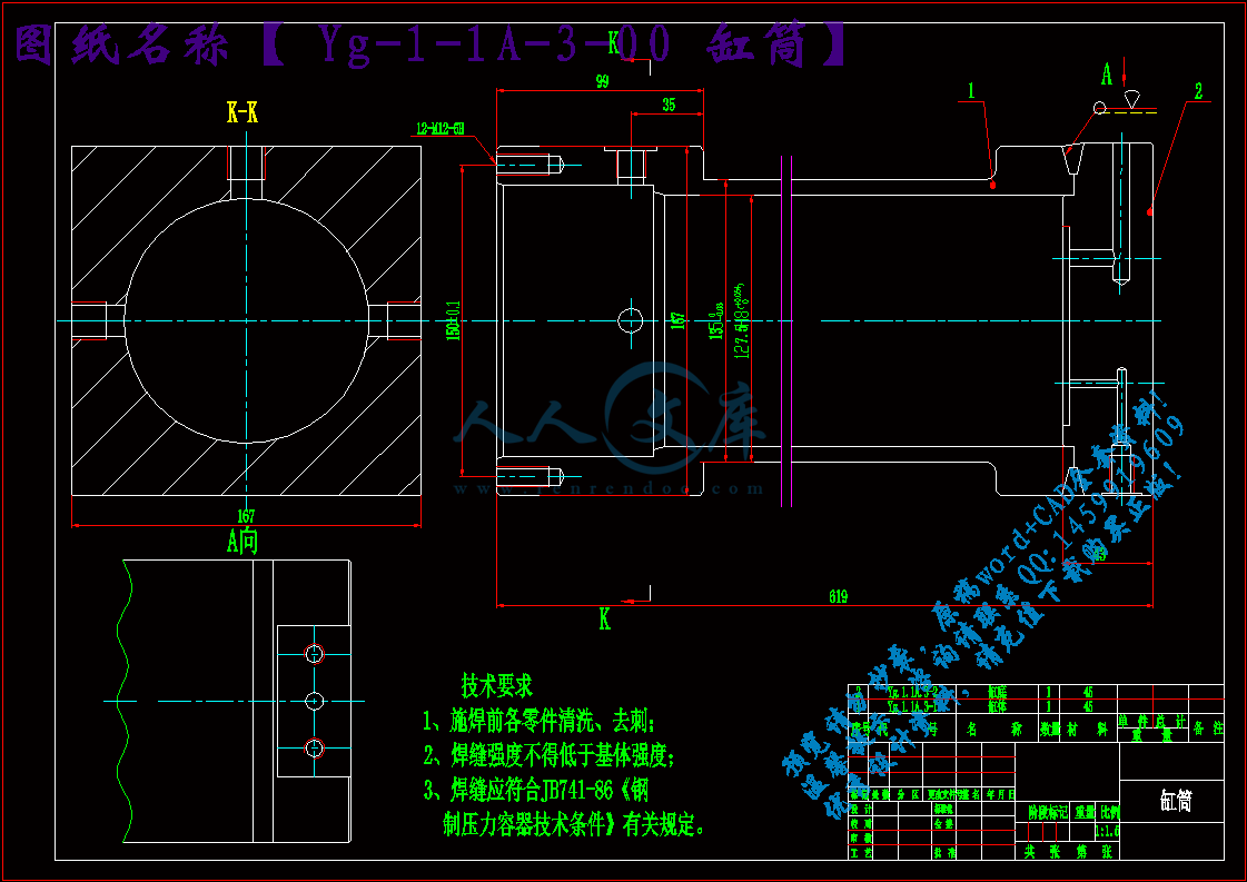
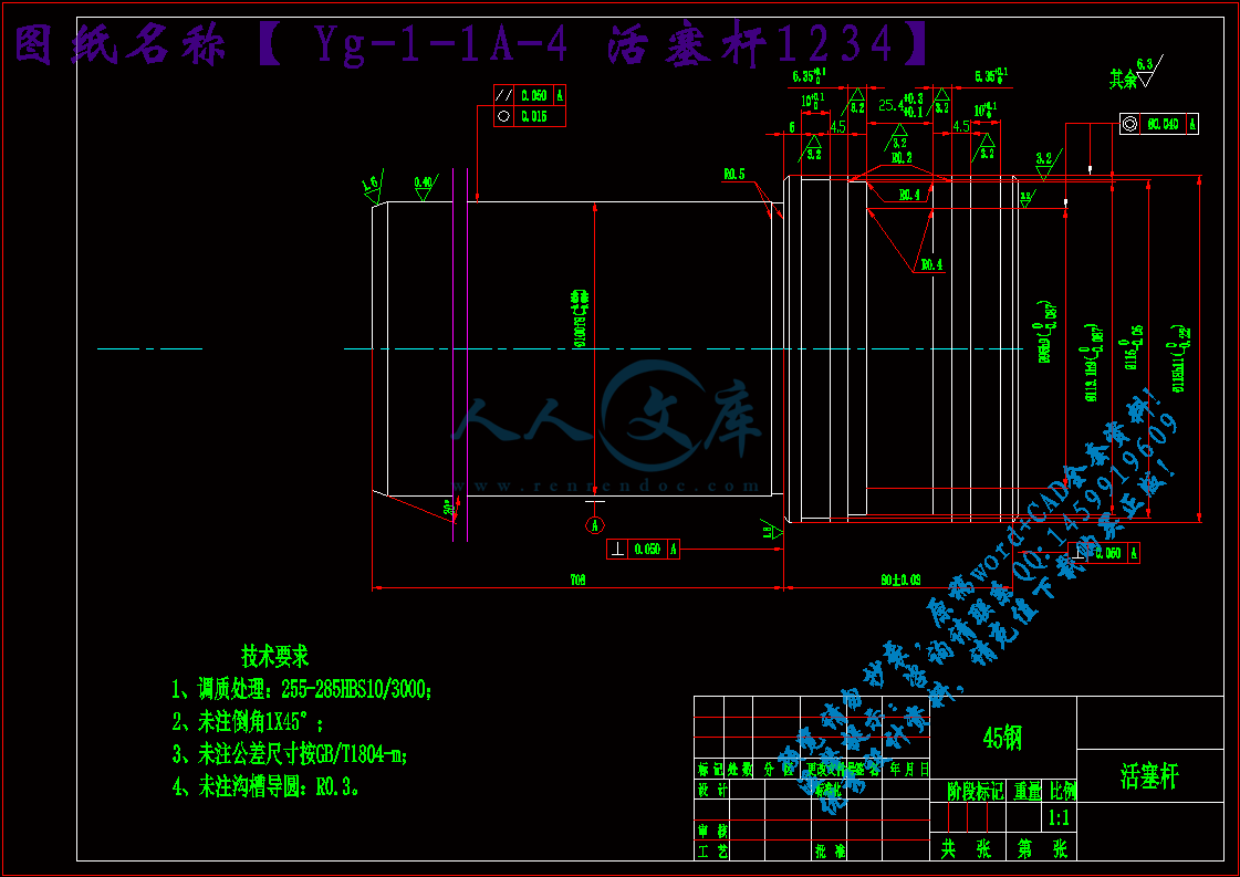
4.1手臂伸缩液压缸的尺寸设计与校核12

4.2 液压缸的密封设计14

4.3 支承导向的设计15

4.4 防尘圈的设计15

4.5 液压缸材料的选用16

第5章 左右方向液压缸设计17

5.1  液压缸主要尺寸的确定17

5.2:液压缸的密封设计19

5.3、支承导向的设计20

5.4:防尘圈的设计20

5.5:液压缸材料的选用20

第6章 连接螺栓设计和校核21

6.1连接方式的选择21

6.2连接处的载荷及其强度校核与设计21

总结22

致谢22

参考文献23

多功能沥青路面养护车的结构设计

 摘要:自改革开放以来, 我国主要发展经济, 加大了对公路等基础设施建设的投资的力度, 公路交通事业经过了20 多年的快速发展,国家“ 十二五” 规划预计的公路总里程将达450 万公里, 高速公路通车的总里程将达到了11万公里.近年来国家对公路养护的节能减排工作高相当重视, 国家对公路建养越来越重视, 在《公路水路交通中长期科技发展规划纲要2006 一2020)、《公路水路交通运输“ 十二五” 科技发展规划》、《产业结构调整指导目录(2011年本) 》中都做出了重要规划, 并制定了与之配套的大力的科技投入、税收鼓励、金融支持、研发能力及其他方面的政策支持。 在交通物流行业快速发展的今天, 为减少因公路养护维修造成交通的拥堵和不便, 给公路养护维修技术提出了更苛刻要求, 公路养护专用车因其快速、灵活机动的特性, 大量的广泛的应用在公路养护维修中。

公路的养护车是一种用在沥青公路路面的养护机械设备.该车的凿槽机构是用于将需要修复的路面进行破坏的结构。现在,无论国产还是进口养护车具有凿槽功能的绝大多采用的是人工手持风镐、液压镐或电镐,对操作工人来说重量重且冲击力大,很不利于广大工人的身心健康。并且,由于人工手持只能用小型冲击镐,凿槽的冲击力很不足且无法连续作业,效率很低,同时边线也不能凿直。

使用此凿槽机械手的优势有:此凿槽机构工作的时候比传统的人工手持风镐、液压镐或电镐要效率高。速度快、定位准确、边线整齐同时深度一致,并且是由液压系统和电控系统控制,大大的提高了工作效率,并为用电脑进行全自动控制留下了技术空间.

通过液压传动和电气控制的结合,用来驱动大功率液压镐,同时使其实现了5个自由度的手动和半自动的凿槽作业。

关键词:多功能沥青路面养护车 凿槽机构 机械手 液压传动

Structure design of multi function asphalt pavement maintenance truck

Abstract: Since the reform and opening up, China's economic development, the highway infrastructure construction investment, the highway after 20 years of rapid development, the national "Twelfth Five Year Plan" is expected to total highway mileage will reach 4500000 km, highway traffic mileage will reach 110000 km. In recent years, energy saving and emission reduction work to highway maintenance the state attaches great importance to the national construction and maintenance, more attention to the highway, waterway transportation in the "medium and long term science and technology development plan of highway 2006 a 2020)," highway and waterway transportation "1025" science and technology development plan "," adjustment of industrial structure to guide catalog (2011 version) "have made important planning, and to develop and supporting science and technology investment, tax incentives, financial support, research and development ability and other aspects of policy support. In the development of the transport and logistics industry growing today, in order to reduce the highway maintenance repair caused traffic congestion and inconvenience to road maintenance, repair technology demanding more, road maintenance vehicle based on the characteristics of fast, flexible, a widely used in highway maintenance and repair.

Chisel groove mechanism of the vehicle is used for structure will need to repair the pavement damage. At present, domestic or imported maintenance vehicle where a gouge function most artificial hand hammer, hydraulic pickaxe or hammer, for the operation of workers with heavy weight and large impact force, is not conducive to the health of workers. In addition, because the artificial hand can only use a small impact pickaxe, gouge impact power obviously insufficient and not continuous operation, low efficiency, also cannot cut straight edge.

Use this gouge manipulator has the advantages of: the work of the slotting mechanism than traditional artificial hand hammer, hydraulic pickaxe or hammer to higher efficiency. Faster, accurate positioning, edge neat and uniform depth, and is controlled by the electric control system of hydraulic system, improve work efficiency, and automatic control technology for the use of computer space left.

Through the combination of hydraulic and electric control, to drive high-power hydraulic pickaxe, and enable it to achieve 5 degree of freedom of the manual and semi automatic mortising slot assignment.

Keywords: multi function asphalt pavement maintenance truck    Chisel groove    mechanism  Manipulator    Hydraulic transmission

              第1章 绪论

1项目研究的背景和意义

1.1路面养护再生技术与设备大力发展

 近年以来国家对公路养护节能减排工作高度重视, 先后发布了国务院《节能减排综合性工作方案》、《交通部关于进一步加强交通行业节能减排工作的意见》(交体法发[2007]242 号) 、交通运输部《资源节约型环境友好型公路水路交通发展政策) (交科教发〔2009 〕80 号) 、2010年4 月19 日国家发改委同中国人民银行与银监会和证监会一起联合发布了《关于支持循环经济发展的投融资政策措施意见的通知》、交通运输部《交通运输“ 十二五” 发展规划》, 其中明确构架了“ 绿色交通” , 大力探索交通运输资源的循环利用的新发展模式, 完善了相关的标准规范和评价指标的体系。积极推广使用交通废弃物(废水)循环利用的新材料、新工艺以及新设备, 倡导标准化的设计及工厂化预制, 提高了资源的再利用水平。加强了港口、公路等的生产、生活污水循环利用效率, 大力开展路面材料、施工的废料、弃渣、港口疏浚土等资源再生和综合利用, 建设资源循环利用试点工程。以工程应用急需的高性能材料、工艺和装备为重点, 积极推广废旧路面材料冷再生、热再生等循环利用技术和施工工艺。

参考文献        

[1]  王宜登,林伟.浅谈我国公路养护设备的发展方向[C].第八届河南省汽车工程科技学 术研讨会论文集.2012.                                                        

[2]  长安大学.一种高海拔低温地区沥青路面快速多功能养护车:中国.2013.                                                              

[3]  查官飞,于勇,邓久军等.新型沥青路面养护车的稳定性设计分析[J].专用汽车,2010

[4]  王忠生.公路养护车用凿槽机械手.工程机械2002,33(9)

[5]  陈金龙.一种新型的沥青路面养护车设计[J].专用汽车,2009(3):56-57.

[6]  徐达,蒋崇贤.专用汽车结构与设计[M].北京:北京理工大学出版社,l998.

[7]  冯晋祥.专用汽车设计[M].北京:人民交通出版社,2007.

[8]  苗永权.专用汽车改装稳定性设计[J].装备制造技术,2008(6):64-67.

[9]  2010年公路水路交通运输行业发展统计公报[R].交通运输部综合规划司

[10] 交通运输部“ 十二五” 规划[R]. 交通运输部

内容简介:
湘潭大学机械工程学院毕业论文(设计)工作中期检查表系 机械工程 专业 机械设计制造及其自动化 班级 二班 姓 名陈维佳学 号2010500412指导教师朱石沙指导教师职称教授题目名称凿槽机械手的设计题目来源 1 科研 企业 其它课题名称多功能沥青路面养护车的结构设计题目性质 1 工程设计 理论研究 科学实验 软件开发 综合应用 其它资料情况1、选题是否有变化 有 1 否2、设计任务书 1 有 否3、文献综述是否完成 1 完成 未完成4、外文翻译 完成 1 未完成由学生填写 方案结构设计完成,参数计算基本完成,接下来尽快完成参数计算,绘制图纸,外文翻译等工作。由老师填写工作进度预测(按照任务书中时间计划) 提前完成 按计划完成 拖后完成 无法完成工作态度(学生对毕业论文的认真程度、纪律及出勤情况): 认真 较认真 一般 不认真质量评价(学生前期已完成的工作的质量情况) 优 良 中 差存在的问题与建议: 指导教师(签名): 年 月 日建议检查结果: 通过 限期整改 缓答辩系意见: 签名: 年 月 日注:1、该表由指导教师和学生填写。2、此表作为附件装入毕业设计(论文)资料袋存档。湘 潭 大 学毕业论文(设计)任务书论文(设计)题目: 多功能沥青路面养护车的结构设计 学号: 2010500412 姓名: 陈维佳 专业: 机械设计制造及其自动化 指导教师: 朱石沙 系主任: 一、主要内容及基本要求 查阅相关文献资料,掌握多功能沥青路面养护车的国内外发展动态,完成多功能沥青路面养护车的结构和动力系统的相关设计。 要求: 1、查阅相关资料,掌握沥青路面综合养护车的结构和工作原理,以及相关知识和科学研究动态; 2、设计多功能沥青路面养护车液压控制系统 3、设计一款路面养护车的凿槽机构 3、2张A0图纸; 4、撰写毕业设计说明书。 5、相关外文文献翻译,字数3000字以上。 二、重点研究的问题 多功能沥青路面养护车的液压控制系统和凿槽机构的设计 三、进度安排序号各阶段完成的内容完成时间1查阅资料、调研第1-2周2开题报告、制订设计方案第3周3方案(设计)第4-5周4设计多功能沥青路面养护车液压控制系统、凿槽机构第6-7周5写出初稿,中期检查第8-9周6修改,写出第二稿第10-11周7写出正式稿第12-13周8答辩第14周四、应收集的资料及主要参考文献 LLY500型多功能沥青路面养护车J.建筑机械(下半月),2011. 王宜登,林伟.浅谈我国公路养护设备的发展方向C./第八届河南省汽车工程科技学 术研讨会论文集.2012. 长安大学.一种高海拔低温地区沥青路面快速多功能养护车:中国.2013. 查官飞,于勇,邓久军等.新型沥青路面养护车的稳定性设计分析J.专用汽车,2010. 湘潭大学毕业设计说明书题 目: 多功能沥青路面养护车的结构设计 学 院: 机械工程学院 专 业: 机械设计制造及其自动化 学 号: 2010500412 姓 名: 陈维佳 指导教师: 朱石沙 完成日期: 目录摘要3第1章 绪论51项目研究的背景和意义52国内外研究现状7第2章 任务特点9第3章 方案设计103.1 机械手的设计要求103.2 机械手的整体设计方案103.3机械手的手臂结构方案设计113.4机械手的驱动方案设计11第4章 前后方向的液压缸设计124.1手臂伸缩液压缸的尺寸设计与校核124.2 液压缸的密封设计144.3 支承导向的设计154.4 防尘圈的设计154.5 液压缸材料的选用16第5章 左右方向液压缸设计175.1 液压缸主要尺寸的确定175.2:液压缸的密封设计195.3、支承导向的设计205.4:防尘圈的设计205.5:液压缸材料的选用20第6章 连接螺栓设计和校核216.1连接方式的选择216.2连接处的载荷及其强度校核与设计21总结22致谢22参考文献23多功能沥青路面养护车的结构设计 摘要:自改革开放以来, 我国主要发展经济, 加大了对公路等基础设施建设的投资的力度, 公路交通事业经过了20 多年的快速发展,国家“ 十二五” 规划预计的公路总里程将达450 万公里, 高速公路通车的总里程将达到了11万公里.近年来国家对公路养护的节能减排工作高相当重视, 国家对公路建养越来越重视, 在公路水路交通中长期科技发展规划纲要2006 一2020)、公路水路交通运输“ 十二五” 科技发展规划、产业结构调整指导目录(2011年本) 中都做出了重要规划, 并制定了与之配套的大力的科技投入、税收鼓励、金融支持、研发能力及其他方面的政策支持。 在交通物流行业快速发展的今天, 为减少因公路养护维修造成交通的拥堵和不便, 给公路养护维修技术提出了更苛刻要求, 公路养护专用车因其快速、灵活机动的特性, 大量的广泛的应用在公路养护维修中。公路的养护车是一种用在沥青公路路面的养护机械设备.该车的凿槽机构是用于将需要修复的路面进行破坏的结构。现在,无论国产还是进口养护车具有凿槽功能的绝大多采用的是人工手持风镐、液压镐或电镐,对操作工人来说重量重且冲击力大,很不利于广大工人的身心健康。并且,由于人工手持只能用小型冲击镐,凿槽的冲击力很不足且无法连续作业,效率很低,同时边线也不能凿直。 使用此凿槽机械手的优势有:此凿槽机构工作的时候比传统的人工手持风镐、液压镐或电镐要效率高。速度快、定位准确、边线整齐同时深度一致,并且是由液压系统和电控系统控制,大大的提高了工作效率,并为用电脑进行全自动控制留下了技术空间.通过液压传动和电气控制的结合,用来驱动大功率液压镐,同时使其实现了5个自由度的手动和半自动的凿槽作业。关键词:多功能沥青路面养护车 凿槽机构 机械手 液压传动Structure design of multi function asphalt pavement maintenance truckAbstract: Since the reform and opening up, Chinas economic development, the highway infrastructure construction investment, the highway after 20 years of rapid development, the national Twelfth Five Year Plan is expected to total highway mileage will reach 4500000 km, highway traffic mileage will reach 110000 km. In recent years, energy saving and emission reduction work to highway maintenance the state attaches great importance to the national construction and maintenance, more attention to the highway, waterway transportation in the medium and long term science and technology development plan of highway 2006 a 2020), highway and waterway transportation 1025 science and technology development plan , adjustment of industrial structure to guide catalog (2011 version) have made important planning, and to develop and supporting science and technology investment, tax incentives, financial support, research and development ability and other aspects of policy support. In the development of the transport and logistics industry growing today, in order to reduce the highway maintenance repair caused traffic congestion and inconvenience to road maintenance, repair technology demanding more, road maintenance vehicle based on the characteristics of fast, flexible, a widely used in highway maintenance and repair.Chisel groove mechanism of the vehicle is used for structure will need to repair the pavement damage. At present, domestic or imported maintenance vehicle where a gouge function most artificial hand hammer, hydraulic pickaxe or hammer, for the operation of workers with heavy weight and large impact force, is not conducive to the health of workers. In addition, because the artificial hand can only use a small impact pickaxe, gouge impact power obviously insufficient and not continuous operation, low efficiency, also cannot cut straight edge.Use this gouge manipulator has the advantages of: the work of the slotting mechanism than traditional artificial hand hammer, hydraulic pickaxe or hammer to higher efficiency. Faster, accurate positioning, edge neat and uniform depth, and is controlled by the electric control system of hydraulic system, improve work efficiency, and automatic control technology for the use of computer space left.Through the combination of hydraulic and electric control, to drive high-power hydraulic pickaxe, and enable it to achieve 5 degree of freedom of the manual and semi automatic mortising slot assignment.Keywords: multi function asphalt pavement maintenance truck Chisel groove mechanism Manipulator Hydraulic transmission 第1章 绪论1项目研究的背景和意义1.1路面养护再生技术与设备大力发展 近年以来国家对公路养护节能减排工作高度重视, 先后发布了国务院节能减排综合性工作方案、交通部关于进一步加强交通行业节能减排工作的意见(交体法发2007242 号) 、交通运输部资源节约型环境友好型公路水路交通发展政策) (交科教发2009 80 号) 、2010年4 月19 日国家发改委同中国人民银行与银监会和证监会一起联合发布了关于支持循环经济发展的投融资政策措施意见的通知、交通运输部交通运输“ 十二五” 发展规划, 其中明确构架了“ 绿色交通” , 大力探索交通运输资源的循环利用的新发展模式, 完善了相关的标准规范和评价指标的体系。积极推广使用交通废弃物(废水)循环利用的新材料、新工艺以及新设备, 倡导标准化的设计及工厂化预制, 提高了资源的再利用水平。加强了港口、公路等的生产、生活污水循环利用效率, 大力开展路面材料、施工的废料、弃渣、港口疏浚土等资源再生和综合利用, 建设资源循环利用试点工程。以工程应用急需的高性能材料、工艺和装备为重点, 积极推广废旧路面材料冷再生、热再生等循环利用技术和施工工艺。 图1 沥青路面就地热再生机组 图2 厂拌冷再生机组 图3 2 0 1 0 年底路面铺装比例图 图4 共振式破碎机以此为代表的沥青路面场地冷再生、沥青路面就地热再生、水泥路面共振破碎技术和设备将得到大力的推广和发展。国内路面再生设备尚处于起步应用阶段, 目前以鞍山森远路桥有限公司、香港英达科技有限公司的热再生机组, 河南高远公路养护设备股份有限公司的厂拌冷再生机组为代表再生设备正在逐步的走向市场。水泥混凝土路面依靠其相对低廉的造价成本优势,2010年底全国水泥混凝土路面137.5 万公里, 占路面铺装的34.4%, 而水泥混凝土路面的破损维护问题一直是困扰我国公路界的难题, 目前国内尚无此设备技术, 只有美国RM工公司的4 台在国内开始租赁使用。水泥混凝土路面如何翻修尤其是翻修过程中的废旧料再生利用己成为公路养护技术发展必须面对和解决的技术问题。1.2乳化沥青制备及施工设备将得到更多应用 乳化沥青始于20 世纪初, 最早被用于喷洒以减少灰尘, 20 世纪20 年代在道路建设中普遍使用, 其具备: a .不需要用石油溶解为液体, 还可以在不需要特别加热的情况下用途广泛, 这两点因素都有助于能量的储蓄。b. 可以较少环境污染: 从乳化沥青中游离出的碳氢化合物的数量几乎为零。C.一些型号的乳化沥青能够包裹在潮湿的石料表面, 可以减少因加热和风干石料所需要的燃料。d.乳化沥青多种型号的可利用性。最新的沥青型号和实验室程序的改良可以满足计划和随需要的条件。e . 在偏远地区能够用冷材料施工。f.乳化沥青的适用性使其对于现有的道路细微缺陷的预防性保养方面可以达到延长使用寿命的作用。乳化沥青不仅仅用于低等级公路沥青路面的铺筑和养护上, 还用于高等级公路的透层油和粘层油, 公路工程的上、下封层, 旧沥青路面材料的冷再生, 以及在水泥混凝土路面的养护也有大量应用实例。随着乳化沥青的发展, 其专用的制造和施工设备得到讯速的发展和应用, 包括乳化沥青生产设备、用于乳化沥青碎石封层的沥青洒布车、同步碎石,封层车、乳化沥青(改性乳化沥青) 稀浆封层、微表处铺展机等等。 图5 乳化沥青生产车间1.3冷料修补坑槽技术和设备将得到更大发展;冷补沥青混合料是用于日常养护修补路面破损的一种材料(简称:冷补材料), 是路面养护中必不可少的, 其具有: a.能快速修补路面破损, 应急处理路面突发性破坏; b. 可在常温、低温、潮湿条件下施工, 受图5 乳化沥青生产车间气候影响小, 延长施工季节;c .无需加热、节能、环保。d.施工快速高效, 施工后可立即开放交通; e.使用范围广, 可用于公路沥青路面、水泥混凝土路面修补, 也可用于城市、居民小区道路、停车场, 以及地下管线、井周边修补。目前冷拌料大多采用液态沥青(稀释沥青) 为结合料的冷补材料, 其制作工艺、设备复杂, 且成本较高。河南省高远公路养护技术有限公司在2010年研制开发出MOH冷补材料(即有机水硬性复合材料) 和施工设备。MOH材料路面修补车是工程原材料及附属机具的分装载体, 各种机载物料均可在其保质期内随机分存, 机车可以随时处于待命状态, 物料储存以及拌合成型全过程均于常温条件下一机完成。有效解决了乳化沥青受到破乳时间限制, 冷补材料不能长时间保存的技术瓶颈, 大大推动了我国路面冷补技术的发展和应用, 并将掀起路面修补技术和设备的一次变革。 1.4高效、智能专业化的大型专用设备及车辆是未来公路养护的主要方向。在日益强大的交通物流行业发展的今天, 为尽量的减少因公路养护维修造成交通拥堵和不便, 给公路养护维修技术提出更多的苛刻要求, 公路养护专用车以其快速、机动灵活的特性, 大量广泛的应用于公路养护维修中。公路养护专用车根据车辆动力形式, 可划分为整车式和列车式(牵引车与专用半挂车组成) 。整车式公路养护专用车历经多年的发展应用, 目前种类、数量、及质量均有了大的跨越发展, 未来在产品可靠性、智能和多功能方面将是其重点发展方向。列车式即半挂式公路养护专用车是国外目前最为常见工程专用设备形式, 也是我国未来将大力提倡的发展趋势, 半挂式公路养护专用车具有: a .运输能力强: 根据我国国标GB 1589一2004 道路车辆外廓尺寸、轴荷及质量限值要求们, 其外廓尺寸、最大总质量即运输能力相对于整车式而言有较大优势, 可实现高效的运输、作业储备。b.节能环保: 公路养护施工受限于季节气候影响, 环境温度较高或较低都会影响到施工质量, 在施工季节牵引车与半挂车组成施工列车, 可实现高效的施工作业。非施工季节可有效快速分离(即甩挂) , 牵引车可作其他半挂车牵引动力, 能得到综合的充分利用, 有效节约资源。组织开展甩挂运输试点工程, 推进甩挂运输全面发展, 也是交通运输部“ 十二五规划” 将重点实施开展的国家项目。一台专用施工设备或车辆, 具备储存(或分存) 一定的介质能力, 为保证提高施工质量和效率, 缩短施工周期, 通过配套的介质运输车辆或设备组成施工作业机组, 实现连续不间断的工作。 图6 MOH材料路面修补车 图7 MOH材料路面修补车施工现场 图8 整车式 图9 半挂式 1.5 路面无损检测评价设备将得到大力推广应用在国家交通运输部“ 十二五” 重大科技研发专项中明确指出“ 新一代公路基础设施维护技术与装备: 重点突破公路、桥梁和隧道结构状况无损检测、全寿命养护与管理、结构物安全预警与保障、材料循环利用和快速维修等方面的核心技术, 构建我国新一代公路维护技术体系”。目前我国高速公路的通车里程己居世界第二, 己建立了较完善的道路养护管理规定和系统, 这些系统的建立有效地保证了养护的科学性, 但普遍面临数据采集手段相对落后的问题, 因此需要针对道路检测技术开展深入研究。近年来, 随着计算机技术、自动化控制技术、高精度测微技术的进步, 道路检测技术人工检测向自动化检测技术发展, 由破损类检测向无损检测技术发展, 由破损类检测向无损检测技术发展, 由破损类检测向无损检测技术发展、由低速度、低精度向高速度、高精度、综合检测评估的方向发展。图10 美国vvs公司连续式微表处摊铺机2国内外研究现状1 国内情况 自改革开放以来, 我国大力发展经济, 加大对公路等基础设施建设的投资力度, 公路交通事业经过20 多年的快速发展, 截至2010 年底, 公路通车总里程达40 万公里, 全国有铺装路面和简易铺装路面公路里程24.2 万公里, 其中高速公路总里程约7.3 万公里,11 个省份的高速公路里程超过3000 公里川。位居世界第二。国家“ 十二五” 规划预计公路总里程将达450 万公里, 高速公路通车总里程将达到11万公里.2 国际情况 国际上, 欧美等发达国家公路路网已建成完善, 并进入大规模的路网维护、养护阶段, 而大量的发展中国家尤其是亚非拉地区国家则刚进入公路网络的大规模建设阶段。随着世界经济的不断发展, 国际公路建设的黄金时代仍将继续维持20 30 年, 因此未来对公路养护设备的需求将保持继续增长。3 国家政策 国家对公路建养愈发重视, 在公路水路交通中长期科技发展规划纲要2006 一2020)、公路水路交通运输“ 十二五” 科技发展规划、产业结构调整指导目录(2011年本) 中均做出了重要规划, 并制定了与之配套的科技投入、税收鼓励、金融支持、研发能力等方面的政策支持。公路养护技术贯穿公路建养始末, 未来几十年内, 公路养护行业将迅速、蓬勃发展, 养护设备的市场前景广阔。公路养护专用设备制造业作为新兴的行业领域, 先后经历了以下发展历程: 2005 年以来, 专业化、智能高效、环保的大型养护设备开始成为市场的主流, 预防性养护技术、再生技术及橡胶沥青等在中国迅速发展, 以此为代表的微表处稀浆封层设备、碎石封层设备、再生设备在养护工程中发挥重大作用。随着公路养护的要求越来越高, 当前部分产品的性能、品种、数量、质量难以满足我国公路养护的需要, 养护机械(专用车) 将朝着高效、节能的系列化(由中国公路的多地域胜、复嗡导胜所决定)、多功能的智能化方向迈进。2 发展方向 在全球环境气候的日益恶化, 国家建设资源节约型和环境友好型社会的要求, 及科学养护的理念下, 公路养护技术和设备将产生质的飞跃。 第2章 任务特点公路的养护车是一种用于沥青公路路面的养护机械设备,具有对沥青路面的坑槽、裂缝、拥包、沉陷、啃边、松散、泛油、波浪、车辙等病害进行修补养护作业。该车集沥青加热、沥青混合料现场拌和、路面切割破碎、除尘、整平压实等功能.该车的凿槽机构是用于将需要修复的路面进行破坏的结构。液压凿槽机械手夹持的是一台功率为6 kW 的STOPA 型液压冲击镐,液压镐的冲击能265 J,冲击频率ll25 Hz,工作压力l0l2 MPa。凿槽机械手具有五个自由度,如图l 所示。一次停车,凿槽机械手可凿槽面积最大为600x800 mm, 凿槽生产率8 m2/h(当厚度为6 cm 时)。 技术特点:1)与传统的人工持镐开凿作业相比,液压传动的机械手持镐作业,效率高、动作灵活、定位准确、凿槽规范、质量易于保证。 2)液压系统兼作各执行器和液压镐的动力源,操纵控制及调节方便,电控系统配合,提高了自动化程度。由于液压系统的电液控制元件均为开关量,便于采用可编程序控制器(PLC)实施控制。 此机构的传动选择液压传动的原因是:液压传动机械手是以压缩液体的压力来驱动执行机构运动的机械手。其主要特点是:介质李源极为方便,输出力小,液压动作迅速,结构简单,成本低。但是,由于空气具有可压缩的特性,工作速度的稳定性较差,冲击大,而且气源压力较低,抓重一般在30公斤以下,在同样抓重条件下它比液压机械手的结构大,所以适用于高速、轻载、高温和粉尘大的环境中进行工作。液压技术有以下优点: (1)体积小、重量轻,因此惯性力小,当突然过载或停车时,不会发生大的冲击(2)能在给定范围内平稳的自动调节牵引速度,并可实现无极调速; (3)换向容易,在不改变电机旋转方向的情况下,可以较方便地实现工作机构旋转和直线往复运动的转换; (4)液压泵和液压马达之间用油管连接,在空间布置上彼此不受严格限制; (5)由于采用油液为工作介质,元件相对运动表面间能自行润滑,磨损小,使用寿命长; (6)操纵控制简便,自动化程度高; (7)容易实现过载保护。 第3章 方案设计3.1 机械手的设计要求本课题将要完成的主要任务如下: 设计出机械手的各执行机构,包括:手部、手臂等部件的设计。 (一)执行机构包括手部、手腕、手臂等部件。1、手部即与液压镐接触的部件。它的目的是防止液压镐偏离控制它上下移动的液压缸的方向,使其不能左右移动,转动。2、手臂手臂是支承被抓物件、手部、手腕的重要部件。手臂的作用是带动手指去抓取物件,并按预定要求将其搬运到指定的位置。工业机械手的手臂通常由驱动手臂运动的部件(如油缸、液压缸、齿轮齿条机构、连杆机构、螺旋机构和凸轮机构等)与驱动源(如液压、液压或电机等)相配合,以实现手臂的各种运动。3、机座机座是机械手的基础部分,机械手执行机构的各部件和驱动系统均安装于机座上,故起支撑和连接的作用。 3.2 机械手的整体设计方案图3-1所示为机械手的结构示意图,沿汽车大梁方向(纵向)水平安装的两根圆柱形导轨1上装有在液压缸推拉下可纵向移动的构件2,此构件上有一个与大梁上的圆柱形导轨呈空间正交的方槽形内导轨3(设有液压缸和方形空心导柱4),导柱的内端与控制横向移动的液压缸连接,外端与夹持液压镐的夹持头6连接。夹持头由液压马达经齿轮传动在导柱的端部可绕导柱中心以任意角度转动。液压镐又可在夹持头上的导槽内由液压缸推拉上下移动,推拉的行程由霍尔元件控制。在镐钎部分装有由液压马达驱动的槽轮结构以控制凿方形槽镐刃与纵横方向的一致。这样的结构在液压与电气作用下就使镐钎凿槽机械的“手部”具有了5个自由度的动作功能。图中X和y为液压镐在水平面内的横向和纵向位移,分别由液压缸驱动;Z为液压镐的升降位移,由液压缸驱动控制凿槽深度,达到规定深度后自动抬起;为液压镐镐头的回转角,由于采用槽轮机构,镐头能在相互垂直的方向停留,以保证切出矩形槽;为镐头的偏转角,由摆动液压缸控制,根据路面情况可采用最有效的镐头冲击偏转角,以加快挖掘速度。 图3-11-圆柱形导轨;2-纵向移动构件;3-方槽形内导轨;4-方形空心导柱; 5-夹持头上的导槽;6-夹持头;7-液压镐;8-镐头;X-横向移动;Y-纵向移动 ;Z-上下移动;-镐体偏转角; -镐头回转角 3.3机械手的手臂结构方案设计按照工作的要求,本机械手的手臂能伸缩、和左右运动。手臂左右运动是通过立柱来实现的,立柱的横向移动即为手臂的横移。手臂的各种运动由液压缸来实现。3.4机械手的驱动方案设计由于液压传动系统的动作迅速,反应灵敏,阻力损失和泄漏较小,成本低廉因此本机械手采用液压传动方式。第4章 前后方向的液压缸设计4.1手臂伸缩液压缸的尺寸设计与校核 4.1.1、 液压缸工作压力的确定 液压缸的工作压力主要根据液压设备的类型来确定,对于不通用途的液压设备,由于工作条件不同,通常采用的压力范围也不同。根据负载F=1000KN,可知液压缸的工作压力为1.52.0Mpa,由确定液压缸的工作压力P=2.0Mpa。 4.1.2、液压缸缸筒内径D的计算根据已知条件,工作最大负载F=1000N左右,工作压力P=2.0MPa可得液压缸内径D和活塞杆直径d的确定:已知: F=5000N, =2.0MPa, =40mm d=0.75D=0.75x120=33但是此活塞杆会受到液压镐的质量所施加的力,所以最总将杆的直径和液压缸的内径定为: D=120,d=100mm 则 A=11309故必须进行最小稳定速度的验算,要保证液压缸工作面积A必须大于保证最小稳定速度的最小有效面积又:式中:流量阀的最小稳定流量,由设计要求给出。 液压缸的最小速度,由设计要求给出。保证了 4.1.3液压缸活塞杆直径d的确定 由已知条件可查表23.633(GB/T2348-1993),取d=100mm。查表知,45钢的屈服强度按强度条件校核: d 所以符合要求。 4.1.4、液压缸壁厚的计算 液压缸的壁厚由液压缸的强度条件来计算。液压缸的壁厚一般指缸筒结构中最薄处的厚度。从材料力学可知,承受内压力的圆筒,其内应力分布材料规律因壁厚的不同而各异。一般计算时可分为薄壁圆筒和厚壁圆筒。本设计按照薄壁圆筒设计,其壁厚按薄壁圆筒公式计算为: (该设计采用无缝钢管) 即2。0x1.5=3 =100110(无缝钢管),取=100 所以可按经验取值 ,选取壁厚:=14mm 4.1.5、缸体外径尺寸的计算 缸体外径 查机械手册表:外径取130mm 4.1.6、液压缸工作行程的确定 由于在液压缸工作时要完成快进,快退,工进等步骤 即可根据执行机构实际工作的最大长度确定。由上述动作可知工作行程为520mm。 4.1. 7、缸盖厚度的确定 一般液压缸多为平底缸盖,其有效厚度 按强度要求可用下式进行近似计算: 式中: D缸盖止口内径(mm) T缸盖有效厚度(mm) T20.3mm 4.1.8、最小导向长度的确定 当活塞杆全部外伸时,从活塞支承面中点到缸盖滑动支承面中点距离为H,称为最小导向长度。如果导向长度过小,将使液压缸的初始挠度增大,影响液压缸的稳定性,因此在设计时必须保证有一定的最小导向长度。 对一般的液压缸,最小导向长度H应满足: 式中:L液压缸的最大行程(mm) D液压缸内径(mm)所以取H=98mm 4.1.9、活塞宽度B的确定 活塞的宽度B一般取B=(0.6-1.0)D 即B=(0.6-1.0)125=(75-125)mm取B=80mm 4.1.10、缸体长度的确定 液压缸缸体内部的长度应等于活塞的行程与活塞宽度的和。缸体外部尺寸还要考虑到两端端盖的厚度,一般液压缸缸体的长度不应大于缸体内径D的20-30倍。 即:缸体内部长度250+55=305mm 缸体长度(20-30)D=(2500-3750)mm 即取缸体长度为1000mm 4.1.11、液压缸进、出油口尺寸的确定 液压缸的进、出油口可布置在端盖或缸筒上,进、出油口处的流速不大于5m/s,油口的连接形式为螺纹连接或法兰连接。 根据液压缸螺纹连接的油口尺寸系列(摘自GB/T2878-93)及16MPa小型系列单杆自(GB/T2878-93)及20MPa小型系列的单杆液压缸油口安装尺寸(ISO8138-1986)确定。进出油口的尺寸为M14x1.5。连接方式为螺纹连接。4.2 液压缸的密封设计 液压缸要求低摩擦,无外漏,无爬行,无滞涩,高响应,长寿命,要满足伺服系统静态精度,动态品质的要求,所以它的密封与支承导向的设计极为重要,不能简单的延用普通液压缸的密封和支承导向。因此设计密封时应考虑的因素:1 用于微速运动(3-5mm/s)的场合时,不得有爬行,粘着滞涩现象。2 工作在高频振动的场合的,密封摩擦力应该很小且为恒值。要低摩擦,长寿命。3 工作在食品加工、制药及易燃环境的伺服液压缸,对密封要求尤为突出,不得有任何的外渗漏,否则会直接威胁人体健康和安全。4 工作在诸如冶金、电力等工业部门的,更换密封要停产,会造成重大经济损失,所以要求密封长寿命,伺服液压缸要耐磨。5 对于高速输出的伺服液压缸,要确保局部过热不会引起密封失效,密封件要耐高温,要有良好的耐磨性。6 工作在高温、热辐射场合的伺服液压缸,其密封件的材料要有长期耐高温的特性。7 工作介质为磷酸酯或抗燃油的,不能用矿物油的密封风材料,要考虑他们的相容性。8 伺服液压缸的密封设计不能单独进行,要和支承导向设计统一进行统筹安排。 3.2.1静密封的设计静密封的设计要确保固定密封处在正常工作压力的1.5倍工作压力下均无外泄露。静密封通常选用O形橡胶密封圈。根据GB3452.1-92标准,查通用O形密封圈系列(代号G)的内径、截面及公差。 由液压缸装配草图确定:选用 1003.55 G GB3452.1 一个 3.2.2动密封的设计动密封的设计直接关系着伺服液压缸性能的优劣,其设计必须结合支承导向的设计统筹进行。活塞与缸筒之间用Y型密封圈。根据液压传动与控制手册表13-23,查得用226编号的O型密封圈,其尺寸为50.393.53.活塞杆与端盖之间用Y型密封圈,它使双作用元件具有良好的性能,抗挤压性好,尺寸稳定,摩擦力小,耐磨、耐腐蚀性强.4.3 支承导向的设计 伺服液压缸的支承导向装置就是为了防止活塞与缸筒、活塞活塞杆与端盖之间的直接接触,相互摩擦,产生磨损,从而达到降低摩擦,减少磨损,延长寿命,起到导向和支承侧向力的作用.导向环的特点: 1) 避免了金属之间的接触;2) 具有高的径向交荷承触力;3) 能补偿边界力;4) 具有强耐磨性和高寿命;5) 摩擦力小;6) 能抑制机械振动;7) 有良好的防尘效果,不允许外界异物嵌入;8) 保护密封件不受过分挤压;9) 导向时即使无润滑也没有液动力方面的问题;10) 结构简单,安装方便;11) 维修费用小.导向环的作用:导向环安装在活塞外圈的沟槽内或活塞杆导向套内圆的沟槽内,以保证活塞与缸筒或活塞杆与其导向套的同轴度,并用以承受活塞或活塞杆的侧向力,用来对活塞杆导向.根据表24.7-13查得选用GST5908-0630的导向环.导向套的选用为其导向长度A=(0.6-1.0)D=(37.8-63)mm, 取A=98mm4.4 防尘圈的设计 为防止落入活塞杆的尘埃,随着活塞杆的伸缩运动被带进端盖和缸筒内,从而使密封件和支承导向环受到损失和过早的磨损,所以,伺服液压缸还设计安装防尘圈。 防尘圈的选择原则:l 不给伺服液压缸增加摩擦;l 不产生爬行;l 不粘着滞涩;l 不磨损活塞杆。 防尘圈的选择不当,会引起摩擦力的增加,将保护活塞杆表面起润滑作用的粘附性油膜层刮下来,造成粘附性渗漏,这种渗漏在原理上是允许的。防尘圈的作用:以防止活塞杆内缩时把杂质、灰尘及水分带到密封装置区,损伤密封装置。综上所述,防尘圈的尺寸为d=100mm4.5 液压缸材料的选用 4.5.1缸筒 缸筒材料:常用20、35和45号钢的无缝钢管。由于缸筒要与法兰焊接在一起,故选用45号钢的无缝钢管。 缸筒和缸盖的连接方式:因为有连接板的障碍,所以使用焊接的方式。(1) 内径用H8的配合;(2) 内径圆度、圆柱度不大于直径公差之半;(3) 内表面母线直线度在45.0mm长度上,不大于0.03mm;(4) 缸体端面对轴线的垂直度在直径上每100mm上不大于0.04mm;(5) 缸体和端盖采用螺纹连接,用内六角螺栓。 4.5.2活塞 活塞的结构形式应根据密封装置的形式来选择,密封形式根据工件条件而定。 4.5.3活塞杆(1) 活塞杆的外端结构 活塞杆外端与负重连接,其结构形式根据工作要求而定。(2) 活塞杆的内端结构 活塞杆的内端与活塞连接。所有形式均需有锁紧措施,以防止工作时由于往复运动而松开。活塞杆与活塞之间还需安装密封,采用缓冲套的螺纹连接。 4.5.4活塞杆导向套 活塞杆导向套装在液压缸的有杆腔一侧的端盖内,用来对活塞杆导向,其内侧装有密封装置,保证缸筒有杆腔的密封性。外侧装有防尘圈,防止活塞杆内缩时把杂质、灰尘和水分带进密封装置区,损伤密封装置。 4.5.5缓冲装置 当工作机构质量较大,运动速度较高时,液压缸有较大的动量。为了减少液压缸在行程终端由于大的动量造成的液压冲击和噪音,必须采用缓冲装置。当停止位置不要求十分准确时,可在回路中设置减速阀和制动阀,也可以在缸的末端设置缓冲装置。第5章 左右方向液压缸设计5.1 液压缸主要尺寸的确定 5.1.1、 液压缸工作压力的确定液压缸的工作压力主要根据液压设备的类型来确定,对于不通用途的液压设备,由于工作条件不同,通常采用的压力范围也不同。根据负载F=12000KN,查附表7可知液压缸的工作压力为1.52Mpa,由附表1确定液压缸的工作压力P=20Mpa。 5.1.2、液压缸缸筒内径D的计算根据已知条件,工作最大负载F=1060N左右,工作压力P=2.0MPa可得液压缸内径D和活塞杆直径d的确定:已知: F=2000N, =2.0MPa,=40d=0.75D=0.75x150=100mm由于有两个耳环可以减轻活塞杆受到的力,但它需要更大的驱动力,于是可得:D=125,d=90mm A=故必须进行最小稳定速度的验算,要保证液压缸工作面积A必须大于保证最小稳定速度的最小有效面积又:式中:流量阀的最小稳定流量,由设计要求给出。 液压缸的最小速度,由设计要求给出。故查表取D=125当D=125的时,保证了 5.1.3、液压缸活塞杆直径d的确定 由已知条件可查表23.633(GB/T2348-1993),取d=45mm。 查表知,45钢的屈服强度 按强度条件校核: d所以d应大于80mm 所以符合要求。 5.1.4、液压缸壁厚的计算 液压缸的壁厚由液压缸的强度条件来计算。液压缸的壁厚一般指缸筒结构中最薄处的厚度。从材料力学可知,承受内压力的圆筒,其内应力分布材料规律因壁厚的不同而各异。一般计算时可分为薄壁圆筒和厚壁圆筒。本设计按照薄壁圆筒设计,其壁厚按薄壁圆筒公式计算为: (该设计采用无缝钢管) =100110(无缝钢管),取=100 由计算的公式所得的液压缸的壁厚厚度很小,使缸体的刚度不够,如在切削加工过程中的变形,安装变形等引起液压缸工作过程中卡死或漏油。所以用经验法选取壁厚:=14mm 5.1.5、缸体外径尺寸的计算 缸体外径 所以外径取152mm 5.1.6、液压缸工作行程的确定 由于在液压缸工作时要完成如下动作 即可根据执行机构实际工作的最大长度确定。由上述动作可知工作行程为520mm。 5.1.7、缸盖厚度的确定 一般液压缸多为平底缸盖,其有效厚度 按强度要求可用下式进行近似计算: 式中: D缸盖止口内径(mm) T缸盖有效厚度(mm) T70mm 5.1.8、最小导向长度的确定 当活塞杆全部外伸时,从活塞支承面中点到缸盖滑动支承面中点距离为H,称为最小导向长度。如果导向长度过小,将使液压缸的初始挠度增大,影响液压缸的稳定性,因此在设计时必须保证有一定的最小导向长度。 对一般的液压缸,最小导向长度H应满足: 式中:L液压缸的最大行程(mm) D液压缸内径(mm)取H=65mm 5.1.9、活塞宽度B的确定 活塞的宽度B一般取B=(0.6-1.0)D 即B=(0.6-1.0)63=(37.8-63)mm 取B=60mm 5.1.10、缸体长度的确定 液压缸缸体内部的长度应等于活塞的行程与活塞宽度的和。缸体外部尺寸还要考虑到两端端盖的厚度,一般液压缸缸体的长度不应大于缸体内径D的20-30倍。 即:缸体内部长度250+55=305mm 缸体长度(20-30)D=(1260-1890)mm 即取缸体长度为520mm 5.1.11、液压缸进、出油口尺寸的确定 液压缸的进、出油口可布置在端盖或缸筒上,进、出油口处的流速不大于5m/s,油口的连接形式为螺纹连接或法兰连接。 根据液压缸螺纹连接的油口尺寸系列(摘自GB/T2878-93)及16MPa小型系列单杆自(GB/T2878-93)及16MPa小型系列的单杆液压缸油口安装尺寸(ISO8138-1986)确定。进出油口的尺寸为M16x1.5。连接方式为螺纹连接。5.2:液压缸的密封设计 5.2.1静密封的设计 静密封的设计要确保固定密封处在正常工作压力的1.5倍工作压力下均无外泄露。静密封通常选用O形橡胶密封圈。 根据GB3452.1-92标准,查通用O形密封圈系列(代号G)的内径、截面及公差。 由液压缸装配草图确定:选用 903.55 G GB3452.1 一个 902.65 G GB3452.1 一个 5.2.2动密封的设计动密封的设计直接关系着伺服液压缸性能的优劣,其设计必须结合支承导向的设计 统筹进行。活塞与缸筒之间用Y型密封圈。根据液压传动与控制手册表13-23,查得用226编号的O型密封圈,其尺寸为50.393.53.活塞杆与端盖之间用Y型密封圈,它使双作用元件具有良好的性能,抗挤压性好,尺寸稳定,摩擦力小,耐磨、耐腐蚀性强.5.3、支承导向的设计导向环的作用:导向环安装在活塞外圈的沟槽内或活塞杆导向套内圆的沟槽内,以保证活塞与缸筒或活塞杆与其导向套的同轴度,并用以承受活塞或活塞杆的侧向力,用来对活塞杆导向.根据表24.7-13查得选用GST5908-0630的导向环.导向套的选用为其导向长度A=(0.6-1.0)D=(37.8-63)mm, 取A=32mm5.4:防尘圈的设计防尘圈的作用:以防止活塞杆内缩时把杂质、灰尘及水分带到密封装置区,损伤密封装置。 综上所述,经查表13-28(液压传动与控制手册),选用丁型无骨架防尘圈,尺寸为45mm5.5:液压缸材料的选用 5.5.1缸筒 缸筒材料:常用20、35和45号钢的无缝钢管。由于缸筒要与法兰焊接在一起,故选用45号钢的无缝钢管。 缸筒和缸盖的连接方式:法兰连接;特点是结构较简单、易加工、易装卸,使用广泛,外形尺寸大,重量大。缸盖的材料为HT200,液压缸内圆柱表面粗糙度为Ra0.2-0.4um。内径用H8的配合;内径圆度、圆柱度不大于直径公差之半;内表面母线直线度在45.0mm长度上,不大于0.03mm;缸体端面对轴线的垂直度在直径上每100mm上不大于0.04mm;缸体和端盖采用螺纹连接,用内六角螺栓。 5.5.2活塞 活塞的结构形式应根据密封装置的形式来选择,密封形式根据工件条件而定。 5.5.3活塞杆 活塞杆的内端与活塞连接。所有形式均需有锁紧措施,以防止工作时由于往复运动而松开。活塞杆与活塞之间还需安装密封,采用缓冲套的螺纹连接 5.5.4活塞杆导向套 活塞杆导向套装在液压缸的有杆腔一侧的端盖内,用来对活塞杆导向,其内侧装有密封装置,保证缸筒有杆腔的密封性。外侧装有防尘圈,防止活塞杆内缩时把杂质、灰尘和水分带进密封装置区,损伤密封装置。 5.5.5缓冲装置 当工作机构质量较大,运动速度较高时,液压缸有较大的动量。为了减少液压缸在行程终端由于大的动量造成的液压冲击和噪音,必须采用缓冲装置。当停止位置不要求十分准确时,可在回路中设置减速阀和制动阀,也可以在缸的末端设置缓冲装置。 第6章 连接螺栓设计和校核 6.1连接方式的选择 采用螺栓连接,4个螺栓均匀分布在连接面上。 6.2连接处的载荷及其强度校核与设计 受横向载荷紧螺栓连接的基本形式如图1所示:图1受横向载荷紧螺栓连接(1)预紧力计算公式: 得预紧力为1500N(3)设计计算公式: 其中为许用挤压压力S为材料的疲劳极限,取300MPa,SS为安全系数,取1.1计算得直径需大于2mm。取直径为8mm。 总结 在没有做毕业设计以前觉得毕业设计只是对这几年来所学知识的单纯总结,但是通过这次做毕业设计发现自己的看法有点太片面。毕业设计不仅是对前面所学知识的一种检验,而且也是对自己能力的一种提高。通过这次毕业设计使我明白了自己原来知识还比较欠缺。自己要学习的东西还太多,以前老是觉得自己什么东西都会,什么东西都懂,有点眼高手低。通过这次毕业设计,我才明白学习是一个长期积累的过程,在以后的工作、生活中都应该不断的学习,努力提高自己知识和综合素质。在我接到任务书之后,我开始按照步骤来进行工作,首先我进行了文献的阅读,对自己所做的课题有了一个大概的了解,随后由于找工作的原因,我的毕业设计的工作进度被推迟了一小段时间。我在之后就开始了机构的设计,如何在车体上安排下这个机构,如何实现它的运动。确定方案之后我就开始参数的计算,确定机构的大小。之后再进行图纸的绘制,在这个过程中,我发现了许多错误,再进行修改。最终得到了现在的方案。致谢在此要感谢我的指导老师对我悉心的指导,感谢老师给我的帮助。在设计过程中,我通过查阅大量有关资料,与同学交流经验和自学,并向老师请教等方式,使自己学到了不少知识,也经历了不少艰辛,但收获同样巨大。在整个设计中我懂得了许多东西,也培养了我独立工作的能力,树立了对自己工作能力的信心,相信会对今后的学习工作生活有非常重要的影响。而且大大提高了动手的能力,使我充分体会到了在创造过程中探索的艰难和成功时的喜悦。虽然这个设计做的也不太好,但是在设计过程中所学到的东西是这次毕业设计的最大收获和财富,使我终身受益。推荐阅读:大学四年就会在这最后的毕业设计总结划上一个圆满的句号.我曾经以为时间是一个不快不慢的东西,但现在我感到时间过的是多么的飞快,四年了,感觉就在一眨眼之间结束了我的大学生涯。毕业,最重要的一个过程,最能把理论知识运用到实践当中的过程就数毕业设计了。这也是我们从一个学生走向社会的一个转折。另一个生命历程的开始。参考文献 1 王宜登,林伟.浅谈我国公路养护设备的发展方向C.第八届河南省汽车工程科技学 术研讨会论文集.2012. 2 长安大学.一种高海拔低温地区沥青路面快速多功能养护车:中国.2013. 3 查官飞,于勇,邓久军等.新型沥青路面养护车的稳定性设计分析J.专用汽车,2010 4 王忠生.公路养护车用凿槽机械手.工程机械2002,33(9) 5 陈金龙.一种新型的沥青路面养护车设计J.专用汽车,2009(3):56-57. 6 徐达,蒋崇贤.专用汽车结构与设计M.北京:北京理工大学出版社,l998. 7 冯晋祥.专用汽车设计M.北京:人民交通出版社,2007. 8 苗永权.专用汽车改装稳定性设计J.装备制造技术,2008(6):64-67. 9 2010年公路水路交通运输行业发展统计公报R.交通运输部综合规划司 10 交通运输部“ 十二五” 规划R. 交通运输部附录外文翻译 原文:Electrorheological fluids are non aqueous suspensions of extremely fine dielectric particles. Under the influence of external electric fields, the enhancement of apparent viscosity of a typical electrorheological fluid can reach as high as 5 orders of magnitude 104, thereby leading to the transformation of electrorheological fluid from the liquid state to the gel state. Winslow 105,106 first noticed the electrorheological effect in the late 1940s, and found that it was because of the fibrillated chains of particles formed in electrorheological suspensions Fig. 8 shows the change of microstructure in an electrorheological fluid subject to an external electric field. Without an electric field, the particles are uniformly suspended in the liquid; while under the effect of an electric field, the particles form chained structures along the direction of the applied electric field. The change of the system from the disordered state to an ordered state is responsible for the incredible increment of apparent viscosity. It should be mentioned that different from other non-Newtonian effects reviewed in the present work, electrorheological effect is not because of EDLs (free charge); instead it is purely due to dielectric response (bond charge) of particles and surrounding liquidmedium. Therefore, in the present review electrokinetics may have a more general definition of the motion induced by electricity, and is not necessarily limited to its classical definition associated with EDLs.The rheological response of electrorheological fluids is commonly characterized by aconstitutive model of Bingham type 107 for N 0eE0T for b 0eE0TWhere ; E0 is the shear stress, is the rate of shear, E0 is the strength of applied electric field, 0(E0) is the dynamic yield stress and pl denotes the plastic viscosity. When subjected to a shear stress higher than 0(E0), the electrorheological fluids behave as liquids and the incremental shear stress ( ; E0.0eE0T) is linearly proportional to the rate of shear. However, when subjected to a shear stress lower than 0(E0),electrorheological fluids behave as solids. Typically, the yield stress 0(E0) varies with the external electric field, while the plastic viscosity pl largely does not depend on the external electric field. The response of shear stress to electric fields is reversible, and is fast with the response time in the order of l100 ms under an electric field of 1 kV/mm. Electrorheological fluids mainly consist of two phases, i.e., a dispersed phase (solid particles) and a continuous phase (nonaqueous/nonpolar liquids). Occasionally, a third phase (additives) is also required to finely tune the properties of electrorheological fluids. The continuous phase is usually various kinds of insulating oils (silicone oil, vegetable oil, mineral oils and so on), and the material of dispersed phase includes myriad of inorganic oxides/non-oxides, organic and polymeric materials 108. It is such rich compositions of electrorheological fluids that primarily determine the electrorheological effects. Themodulation of electrorheological effect can be simply realized by varying the composition of fluids. In addition, the electrorheological effect was found to be influenced by the geometry of the electrodes. The parallel grooved electrodes slightly increased the electrorheological effect and the perpendicular grooved electrodes doubled the electrorheological effect 109; it was believed that these increases in electrorheological effect are achieved by taking advantage of dielectrophoresis of dispersed particles. With electrodes coated with electrically polarizable materials, electrorheological effect can be significantly increased, and the leakage current in electrorheological fluids was minimized 110. Compared to other non-Newtonian electrokinetics reviewed in the present work, electrorheological fluids not only have well-developed theories but also numerous established applications. In the literature, several excellent reviews 107,108,111,112 have been dedicated to electrorheological fluids in terms of mechanisms, models, materials and applications. The intention of the present review is to summarize various non-Newtonian effects in electrokinetics, and electrorheological effect is one of them according to the aforementioned general definition of electrokinetics. However, in order not to compete with those reviews, we herein only provide a very brief discussion of the mechanisms and applications of electrorheological fluids. The major obstacle limiting the use of electrorheological fluids in practical applications is the low yield stress in the mode of shear flows. One way to increase the yield stress is by applying an additional compressive stress on the electrorheological fluid 113. In 2003, Wenet al. 114 discovered another new way of increasing yield stress with the so-called giant electrorheological fluid. The giant electrorheological fluid is formed by dispersing urea-coated nanoparticles of BaTiO(C2O4)2 in the silicone oil. The high dielectric constant of particles, the small size of particles and the urea coating are identified to be responsible for the high yield stress. Another discovery from their investigation is that the yield stress is linearly proportional to the electric field strength when the electric field exceeds 1 kV/mm. This feature is advantageous over conventional electrorheological fluids for which the yield stress is usually nonlinearly related to the electric field strength. In addition, for noticeable electrorheological response, giant electrorheological fluids require much lower electrical field strength and current density in comparison with conventional electrorheological fluids. The applications of electrorheological fluids range from hydraulic valves 115, clutches 116, brakes 117, shock absorbers 118 and haptic controllers 119 to tactile displays 120. Other novel applications of these fluids also have been proposed. Since electrorheological fluids are capable of changing fromthe liquid state to a hard state almost instantaneously under the action of electric fields, the US army has been planning to use them to make bulletproof armors. Furthermore, electronics giant-Motorola filed a patent in 2006 for utilizing electrorheological fluids to make a flexible mobile electronic device. Such device becomes rigid when electrically energized, but can be flexibly bendable when not electrically energized. Because of intrinsic superior electrorheological response, giant electrorheological fluids naturally are suitable for all the above-mentioned purposes. Other than conventional applications at themacroscale, a group from The Hong Kong University of Science and Technology recently utilized electrorheological fluids at the microscale for various microfluidic functionalities, such as microdroplet manipulations, microfluidic logic gates, microvalving, micropumping, and micromixing. For more detailed discussion of microfluidic applications of electrorheological fluids, the readers are referred to recent reviews5.4. Electroviscous effect of colloidal suspensions Generally, the effective viscosity () of a liquid suspension of uncharged spherical particles is higher than that of the pure liquid medium (0). Under the limit of a low volumetric fraction of particles ( 0), the effective viscosity of the particle suspension can be evaluated from the well-known Einstein formula 122,123 However, the particle suspending in an aqueous electrolyte solution acquires electric charge on their surface, and then EDLs have to form around particles to neutralize such surface charge. The bulk fluidmotion relative to particlesmay cause the EDLs in equilibriumto deform,which manifests as an further increase in both energy dissipation and viscosity 124,125. This effect offically termed the primary electroviscous effect was firstly brought into public attention by Smoluchowski 126, and the effective viscosity of liquid suspension can be modified according to the following relation 125 where p(, a/D) is the primary electroviscous coefficient, and it depends on the particle zeta potential and the ratio of the particle radius to the EDL thickness. When the ratio a/D is extremely large (a/D ), hydrodynamic disturbance because of particle surface charge is confined to a thin EDL around the particle and does not affect the bulk fluid field, and hence the electroviscous coefficient p approaches to zero. When a/D is of finite value, the EDL thickness is comparable to the particle size, and thus hydrodynamic disturbance can substantially alter the bulk flow field with large values of p. If the suspension is so concentrated that the EDLs around particles become overlapped (a/D 1), the forces due to EDL repulsion and van derWaals attraction would come into play, and then the secondary electroviscous effect emerges. Finally, we have the tertiary electroviscous effect which results from a change in the conformation of soft particles (such as size and/or shape of polymeric particles and biomolecules). The detailed discussion on three categories of electroviscous effects in colloidal suspensions can be found in books and reviews 7,125,127,128. It is also worth while making a comparison between the electroviscous effect and the electrorheological effect reviewed in the previous section. These two effects are both existent in particle suspensions. However, the continuous phase in electrorheological effect is nonaqueous liquids, while the continuous phase in electroviscous effect is aqueous liquids. The electrorheological effect usually requires a relatively higher volumetric fraction of particles as compared to the electroviscous effect. The viscosity increment due to electroviscous effect usually is limited by a factor of 2. However, the viscosity increment because of the electrorheological effect can reach up to 5 orders in magnitude.6. Conclusions and outlookWe have presented an extensive review of electrokinetics regarding non-Newtonian fluids. This topic is of high relevance for electrokinetically-driven microfluidic and nanofluidic systems which are routinely used to process and analyze non-Newtonian fluids, such as biofluids, polymeric solutions and colloidal suspensions. In particular, Sections 2 to 4 summarize non-Newtonian effects in EDL-related electrokinetics (electroosmosis, electrophoresis and streaming potential). Section 5 presents other related non-Newtonian effects in electrokinetics, including viscoelectric effect, shear-thickening induced by finite size of ions, electrorheological fluids and electroviscous effect of colloidal suspension. The survey of literature suggests that non-Newtonian effects generally lead to a nonlinear dependence of liquid/particle velocity on externally applied electric fields and/or zeta potential. Then it is natural to consider non-Newtonian electrokinetics as a type of nonlinear electrokinetics. In addition to the nonlinearity, the liquid or particle velocity in EDL-related electrokinetics tends to saturation due to the shearthickening behavior of liquids that originates from the shear-rate dependent viscosity, viscoelectric effect, and ionic crowding etc. Obviously, non-Newtonian effects enable electrokinetic phenomena to show an explicit dependence on the fluid rheology. There are still unfilled blanks in this field of research. It is well-known, that electroosmosis, electrophoresis, streaming potential and sedimentation potential are four classic EDL-related electrokinetic phenomena. The first three types of electrokinetic phenomena have been covered in Sections 2 to 4. Clearly, non-Newtonian effects on sedimentation potential of charged particles have been overlooked in the literature. In addition, many investigations 129131 showed that flow enhancement in the pressure-driven flow of non-Newtonian fluids can be achieved by adding an oscillating pressure gradient of small amplitude to a constant pressure gradient. Such flow enhancement is ascribed to reduced effective viscosity due to the small oscillation of pressure gradient. It is then expected that the similar concept of flow enhancement can also be applicable to the electroosmotic flow of non-Newtonian fluids under a combination of a DC field and a small AC field. How would the flow enhancement be? How does such flow enhancement depend on the fluid rheology (thinning versus thickening)? In addition to the enhancement of electroosmotic flow, the enhancement of electrophoretic transport of particles in non-Newtonian fluids is also promising under the combined action of AC and DC electric fields. At last, we put forward some theoretical deficiencies of current theoretical models regarding the EDL-related non-Newtonian electrokinetics, and point out the directions to which such deficiencies could be overcome or alleviated. Admittedly, most studies reviewed in Sections 2, 3 and 4 treated non-Newtonian effects by simply using particular constitutive models of non-Newtonian fluids, and the associated non-Newtonian effect is considered to be homogeneous in the entire liquid domain. Such treatment, however, may not completely reflect the micro/nano scale physics of non-Newtonian fluids. Practically, non-Newtonian fluids are made from suspensions of particles/macromolecules (polymer, DNA, protein etc.). In addition, the characteristic length scales characterizing the inter particle interactions in non-Newtonian fluids and the interactions between the particles in the fluids and the solid surface are usually in order of micrometers or even nanometers. When the liquid is confined into a conventional large scale domain whose dimensions are much larger than these length scales of interactions, the aforementioned interactions do not play significant roles and the fluid rheology can be assumed to be uniform in the entire fluid domain. However, when the liquid is confined into a micro- and nano-scale domain whose dimensions are comparable to these length scales of interactions, the aforementioned interactions become prominent and would introduce several theoretical issues which must be further clarified in EDL-related electrokinetics.6.1. Criterion for non-Newtonian behavior inside EDLThe non-Newtonian behavior in complex fluids results from the reorganization of the microstructure of fluid under the influence of an imposed shear flow. At sufficiently low shear rates, the reorganization is weak, and thus the shear stress is linearly proportional to the rate of shear (Newtonian behavior). When the magnitude of shear rate becomes large enough (comparable to the inverse of relaxation time characterizing a transition process of restoring the initial microstructure distorted by the shear flow), deviation from the Newtonian behavior becomes noticeable. The slowest mechanism of restoration is associated with the thermal motion of particles composing the complex fluids. Widely cited estimation based on the above mechanism shows that the shear stress leading to the non-Newtonian behavior should satisfy the following inequality 132where a is the diameter of dispersed particles and is considered as the characteristic dimension of microstructure. If we consider the shear stress that is developed within a thin EDL over a planar surface, an integration of the Cauchy momentum equation with the far-field boundary condition that 0 and d/dy 0 as y yields Under the DebyeHckel linear approximation, the potential distribution within a thin EDL is expressed as = exp(y), where is the reciprocal of Debye length and is the zeta potential of the charged surface. Using this expression and combining Eqs. (27) and (28), we arrive at the following criterion In Eq. (29), the length scale parameter a* denotes a critical diameter, above which one can expect the non-Newtonian behavior For typical values of = 7 1010F/m (water at room temperature), = 50 mV, = 108/m (103 M 1:1 aqueous electrolyte solution) and E0 = 104 V/m, we obtain that a* 50 nm. According to the above estimation, particles must be larger than 50 nm (definitely larger than the double layer thickness, D = 1 = 10 nm) to allow non-Newtonian effects inside the EDL. Therefore, a question naturally arises, is it still valid to employ the continuum approach to correlate the local stress with local shear rate? Furthermore, even though the continuum approach is valid here, it is still necessary to find complex fluids with the diameter of dispersed particles satisfying the condition D N a N a* under which non-Newtonian effect can prevail inside the EDL. 6.2. Depletion layer due to non-adsorbing particles and adsorption layer due to adsorbing particles Many authors reported the existence of a depletion layer that separates the complex fluid and the solid surface 133138. Such layer is due to the depletion of non-adsorbing particles near the solid surface and thus is occupied by the pure solvent. Therefore, the viscosity of depletion layer is much lower than that of bulk. A typical indication for the existence of depletion layer is the hydrodynamic slip observed in flows of many complex fluids (such as polymeric solutions, emulsions, suspensions of colloid and blood). The thickness of depletion layer is related to the hard spherewall interactions and thus is typically of about the gyration radius of microstructures (polymeric molecules or particles). It is imperative to consider the wall depletion since the EDL related electrokinetic effects take place inside the EDL whose thickness is comparable to that of the depletion layer. Berli and Olivares 23 only addressed a special case in which the thickness of EDL is assumed to be smaller than that of the depletion layer and the liquid viscosity inside the depletion layer is constant (Newtonian liquid). Under these assumptions, electrokinetic effects inside the EDL essentially exhibit Newtonian characteristics, indicating no effect of the bulk rheology. Practically, the liquid viscosity inside the depletion layer varies due to the bulk concentration of polymer and the depletion layer also can be thicker than EDL 138,139. A more general model describing the electrokinetics of non-Newtonian liquids with arbitrary thicknesses of EDL and depletion layer as well as a varying liquid viscosity inside the depletion layer deserves further efforts. For special cases where the thickness of EDL is larger than that of depletion layer, one certainly can anticipate the extension of electrokinetic effects to the bulk of complex fluid and also the effect of bulk rheology on electrokinetic phenomena. Depletion layer discussed above is because of non-adsorbing particles in non-Newtonian fluids. However, there are practically also non-Newtonian fluids composed of adsorbing particles which form an adsorption layer near solid surface 7,140,141. Adsorption of particles (e.g., biological and polymeric molecules) on solid surfaces would alter both physicochemical and hydrodynamic conditions inside the EDL, such as change of the zeta potential, induced local shear-thickening and particlewall collisions, which all could modify the EDL-related electrokinetics. 6.3. Charged particles effect For non-Newtonian fluids formed by suspending particles in aqueous media, it is also quite reasonable to take into account the electrical charges of constituent particles. We consider the electroosmosis of a non-Newtonian fluid in a slit microchannel shown in Fig. 9 to provide a simple picture of the effect of charged particles. Here it is assumed that the constituent particles of non-Newtonian fluids are nonadsorbing, and then the entire channel domain can be divided into two depletion layers near the channel walls and a complex fluid layer in the bulk of channel. For simplifying the analysis, the particles are regarded to be completely depleted from the depletion layers, and then the depletion layers are purely Newtonian solvents (water) and all the particles are confined in the complex fluid layer. Under the effect of the surface charge on channel walls, ions in liquids redistribute to form EDLs which extend from the channel wall into the depletion layer and even the complex fluid layer. Because of the aqueous particle suspension, the particles inside the complex fluid layer are also naturally charged. Similar to ions, the charged particles alsowould redistribute under the influence of the surface charge on channel walls. However,the redistribution of particles should be much weaker than that of ions since the complex fluid layer is far from the channel wall, and also the particles aremoremassive than electrolyte ions. In comparison with ions which follow the Boltzmann distribution inside EDL, the particles in the complex fluid layer can be reasonably assumed to be uniformly distributed. Obviously, the uniformly distributed charged particles would introduce an extra charge density in the complex fluid layer.With the above considerations, the electric fieldwithin the system Fig. 9. Non-Newtonian electroosmosis in a microchannel with the depletion layers near solid walls and the charged complex fluid layer in the bulk. The height of the channel is 2H, the thickness of the depletion layer is , and the two walls are uniformly negatively charged with the zeta potential of which induces electric field in the depletion layer, D, and the complex fluid layer, C. Then an externally applied axial electric field Einteracts with the charge densities inside the depletion layer and the complex fluid layer to induce electroosmosis in the depletion layer, uD, and in the complex fluid layer, uC. sketched in Fig. 9 due to the charged channel walls is governed by the following two equations where , and are the electric potential, the Debye parameter and the electric permittivity, respectively. Parameters with subscript C are associated with the bulk complex fluid layer, while those with subscript D are associated with the depletion layer. The term 2 accounts for the free charge density due to small ions, and q is the charge density inside the complex fluid layer due to the charged constituent particles. Eqs. (31) and (32) are completed by the following boundary conditions以及 The solution of above equations results in the electric field inside the fluid domain which would be required for solving the momentum equation. In this particular case, the depletion layer is Newtonian fluids, and the non-Newtonian characteristics of complex fluid layer are assumed to be described by the power-law constitutive model. Then the solution of the momentum equation gives rise to the following expressions for the fluid velocity in the depletion layer and the complex fluid layer where D is the Newtonian dynamic viscosity of the depletion layer, and n and m are the fluid behavior and consistency indices of the complex fluid layer respectively. A preliminary analysis shows some interesting effects. For example, when zeta potential and charge density q have the same signs, an increase of the electric field strength may change the sign of velocity in the complex fluid layer. Additionally, the above simple model does not consider the EDLs formed at the interfaces between the complex fluid layer and depletion layers. The existence of such EDLs would exert extra electric stresses on the interfaces, and thus is believed to further alter electrokinetic phenomena.Other than the aforementioned three major theoretical concerns, the application of famous power-law constitutive model to non-Newtonian EDL-related electrokinetics in most reviewed investigations remains questionable. As is known, an established criterion of good constitutive models is that they always should describe the Newtonian behavior at low shear stresses 142,143. Apparently, the power-law model does not meet this criterion. For instance, as the velocity gradient approaches asymptotically to zero outside the EDL, the power-law model predicts an unphysical infinite viscosity for shear-thinning fluids. When addressing the EDL-related electrokinetics of non-Newtonian fluid, one probably should use other constitutive models (such as the Carreau model) rather than the power-law model to describe the rheology of fluids. Certainly, there are burgeoning interests in electrokinetic phenomena involving non-Newtonian fluids, especially the EDL-related electrokinetic phenomena reviewed in Sections 2 to 4. Notably, researches in the current literature mainly focus on theoretical investigations which mostly are lack of experimental validations.Moreover, three theoretical considerations described above also need solid experimental verification.Thus, we have good reasons to expect booming experimental investigations of the EDL-related electrokinetics of non-Newtonian fluids in the near future. At last, it needs to be highlighted that apart from fundamental aspects of electrokinetics of non-Newtonian liquids discussed above, exploitation of its practical applications also may attract the attention of future investigations. Apparently from the review, three types of EDL-related electrokinetics of non-Newtonian fluids (electroosmosis, electrophoresis, and streaming potential effect of non-Newtonian fluids) mainly undergo theoretical investigations at present, because they are still in the early stage of development. As a consequence, there are very few established applications for such three effects. For example, electroosmosis of non-Newtonian fluids is only suggested conceptually for pumping, solute transport and heat transport as mentioned at the end of Section 2, but there are no experimental demonstrations of these applications as far as we know. The electric display mentioned in the second paragraph of Section 3 could be the only established application of electrophoresis of non-Newtonian fluids at the moment, and the established application of streaming potential effect of non-Newtonian fluids is only limited to the power generation as mentioned at the beginning of Section 4. For viscoelectric and ioncrowding effects reviewed in Section 5, at present they do not have any practical applications yet. These two mechanisms are mainly used to explain the discrepancy between the experimental observations and the classical HelmholtzSmoluchowski theory 译文:5.3 电流变流体电流变流体是非水的精细的介电粒子组成的悬浮体。在外加电场的影响下,一种典型电流变流体的表观粘度可以提高5个数量级104,从而导致电流变流体从液态转换为凝胶状态。Winslow在20世纪40年代晚期首先注意到了电流变流体效应,并发现是由于原纤维化粒子形成了电流变流体悬浮体造成的。图8展示了电流变流体在外加电场中微观结构的变化。没有外加电场时,粒子在液体中均匀悬浮;在外加电场的影响下,粒子沿着所加电场的方向形成了链式结构。系统从无序状态变为有序状态导致了表观粘度不可思议的增长。值得注意的是,与我们之前讨论的非牛顿效应不同,电流变流体效应不是由于EDLs(自由电荷),相反的,它完全是由于粒子和周围液体介质的介电效应(束缚电荷)造成的。因此,在过去的电动力学讨论中也许有对于由电诱导产生的运动的更一般的定义,并不一定限于与EDL相关的经典定义。电流变流体的流变响应通常用Bingham型的本构模型描述:,对于大于(),对于小于()是剪切应力,是剪切速率,是外加电场强度,是动态屈服应力,代表塑性粘度。当受到比()大的剪切应力时,电流变流体表现为液体,剪切应力增量(-)和剪切大小成正比。然而,当受到的剪切应力小于时,电流变流体表现为固体。典型情况下,屈服应力与外加电场有关,而塑性粘度很大程度上和外电场无关。对电场的响应剪切应力是可逆的,并且在1kV/mm的电场下,相对于100ms的量级响应很快。电流变流体主要由两相构成,即分散相(固体颗粒)和连续相(非水/非极性液体)。有时,我们需要第三相(添加剂)来微调电流变流体的性质。连续相通常由各种绝缘油(硅油,植物油,矿物油等等),分散相的材料包括无数的无机氧化物/非氧化物,有机和聚合物材料。它有如此丰富的电流变流体成分,通常决定了电流变效应。这种对电流变效应的调制可以简单地通过改变流体成分认识到。此外,电流变效应受电极几何形状影响。平行槽电极略微增加电流变效应,而垂直槽电极会使电流变效应加倍。有人认为,这些电流变效应的增加是通过分散粒子的介电电泳达到的。使用涂有导电材料的可极化电极可以显著增加电流变效应,电流变流体的泄露电流也会最小
温馨提示:
1: 本站所有资源如无特殊说明,都需要本地电脑安装OFFICE2007和PDF阅读器。图纸软件为CAD,CAXA,PROE,UG,SolidWorks等.压缩文件请下载最新的WinRAR软件解压。
2: 本站的文档不包含任何第三方提供的附件图纸等,如果需要附件,请联系上传者。文件的所有权益归上传用户所有。
3.本站RAR压缩包中若带图纸,网页内容里面会有图纸预览,若没有图纸预览就没有图纸。
4. 未经权益所有人同意不得将文件中的内容挪作商业或盈利用途。
5. 人人文库网仅提供信息存储空间,仅对用户上传内容的表现方式做保护处理,对用户上传分享的文档内容本身不做任何修改或编辑,并不能对任何下载内容负责。
6. 下载文件中如有侵权或不适当内容,请与我们联系,我们立即纠正。
7. 本站不保证下载资源的准确性、安全性和完整性, 同时也不承担用户因使用这些下载资源对自己和他人造成任何形式的伤害或损失。
提示  人人文库网所有资源均是用户自行上传分享,仅供网友学习交流,未经上传用户书面授权,请勿作他用。
关于本文
本文标题:多功能沥青路面养护车的液压系统设计【优秀】【word+9张CAD图纸全套】【液压系统类】【毕设】
链接地址:https://www.renrendoc.com/p-306085.html

官方联系方式

2:不支持迅雷下载,请使用浏览器下载   
3:不支持QQ浏览器下载,请用其他浏览器   
4:下载后的文档和图纸-无水印   
5:文档经过压缩,下载后原文更清晰   
关于我们 - 网站声明 - 网站地图 - 资源地图 - 友情链接 - 网站客服 - 联系我们

网站客服QQ:2881952447     

copyright@ 2020-2025  renrendoc.com 人人文库版权所有   联系电话:400-852-1180

备案号:蜀ICP备2022000484号-2       经营许可证: 川B2-20220663       公网安备川公网安备: 51019002004831号

本站为文档C2C交易模式,即用户上传的文档直接被用户下载,本站只是中间服务平台,本站所有文档下载所得的收益归上传人(含作者)所有。人人文库网仅提供信息存储空间,仅对用户上传内容的表现方式做保护处理,对上载内容本身不做任何修改或编辑。若文档所含内容侵犯了您的版权或隐私,请立即通知人人文库网,我们立即给予删除!