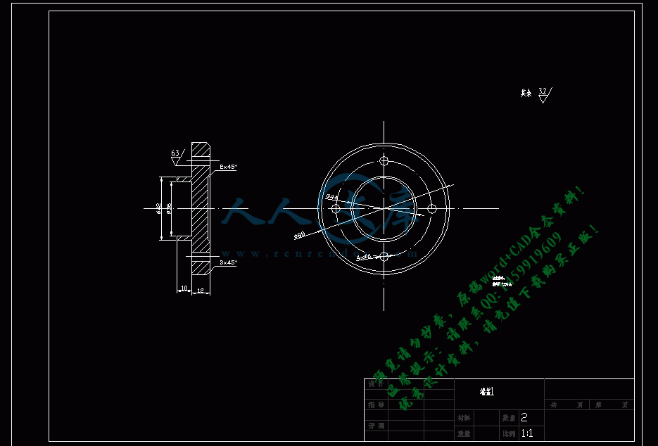
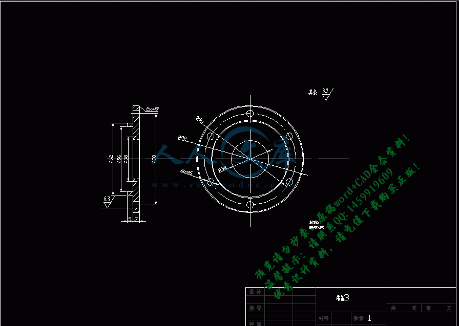
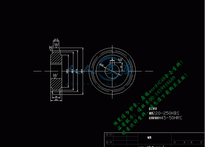
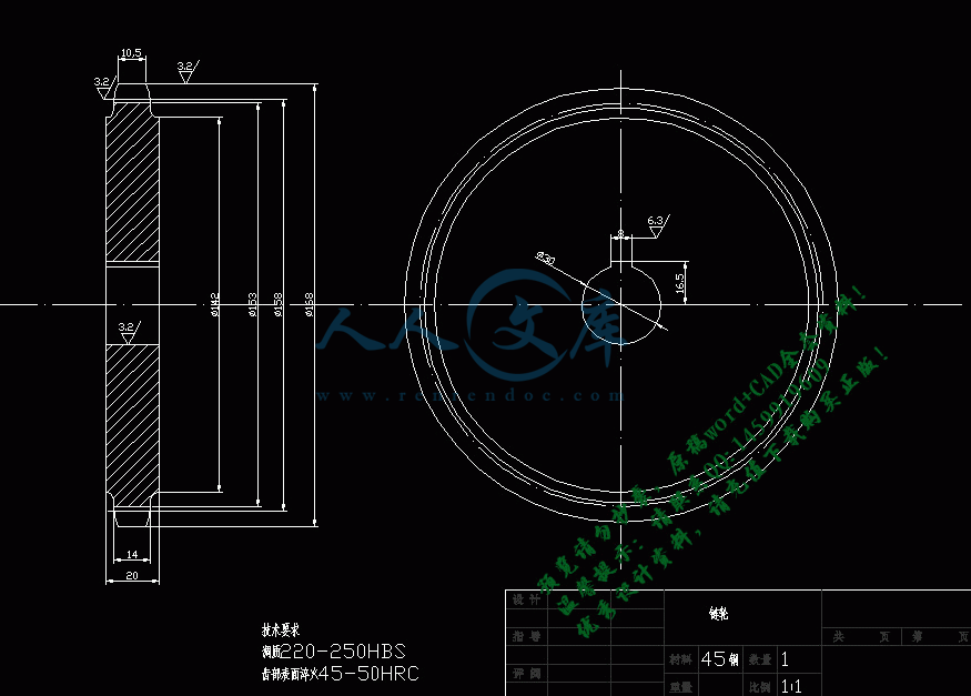
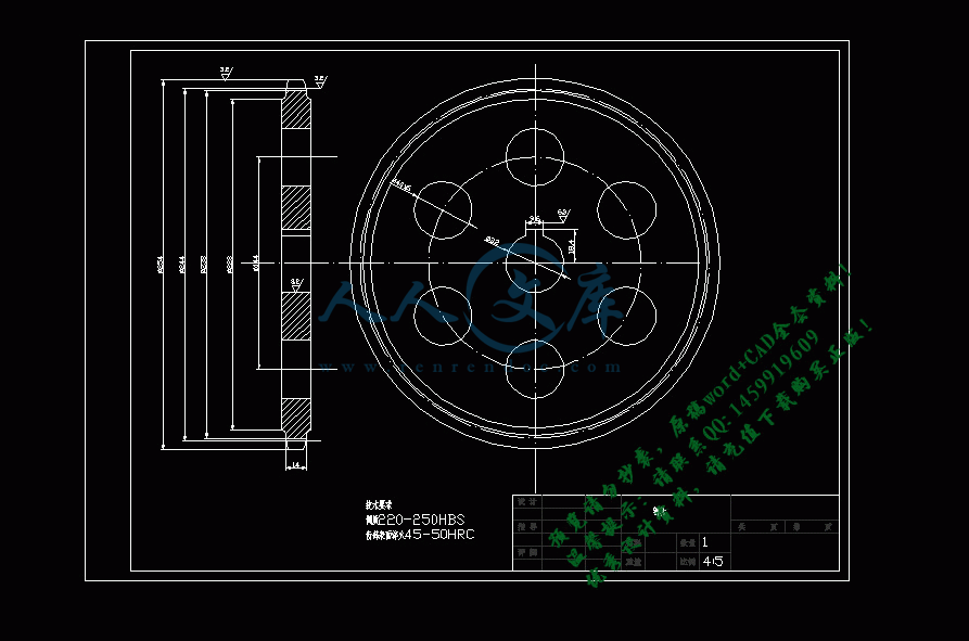
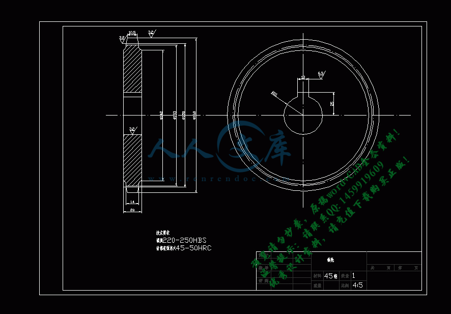
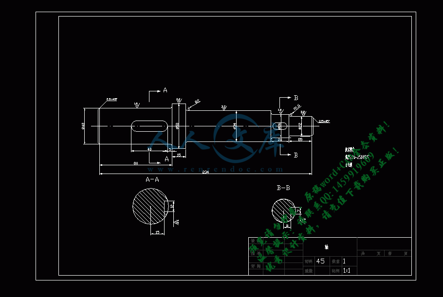
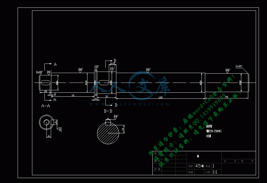
链轮4.dwg
链轮4.dwg

多功能封口机的结构设计【优秀】【word+15张CAD图纸】

收藏

资源目录
跳过导航链接。
压缩包内文档预览:
预览图
编号:316892    类型:共享资源    大小:11.06MB    格式:RAR    上传时间:2014-08-29 上传人:QQ14****9609 IP属地:陕西
48
积分
关 键 词:
多功能 封口机 结构设计 机械设计
资源描述:

多功能封口机的设计

多功能封口机的结构设计【优秀】【word+15张CAD图纸】【毕业设计】

【带任务书+开题报告+文献综述+外文翻译】【28页@正文7900字】【详情如下】【需要咨询购买全套设计请加QQ1459919609】.bat

任务书.doc

填料斗.dwg

多功能包装机装配图.dwg

多功能封口机结构设计参考.docx

导辊心轴.dwg

开题报告.doc

摘要+目录.doc

文献综述.docx

文献翻译.doc

模板

横封辊.dwg

正文.docx

直齿圆柱齿轮齿轮.dwg

端盖1.dwg

端盖2.dwg

端盖3.dwg

草稿

资料

轴1.dwg

轴2.dwg

轴3.dwg

链轮1.dwg

链轮2.dwg

链轮3.dwg

链轮4.dwg

任务书

课题内容

   本课题的内容是关于多功能封口机的设计,主要包括多功能封口机的结构设计以及对现有产品的结构优化和创新。能够实现较高的自动化程度和生产效率,如1)设计封口机的多功能化,实现其从填料到封口一体化;2)优化结构计算填料与封口之间的运动时间关系,提高工作效率;3)设计简易的填料和封口装置,减少设备耗材与复杂程度,提高设备工作质量与工作效率。主要研究对象是多功能封口机的结构设计,通过Solidworks等三维建模软件对设计的封口机进行三维造型与仿真,利用有限元分析等计算填料和封口部分的疲劳强度等。将三维造型图转化为工程图,计算并确定结构参数,完成零件图的绘制与标注,最后完成对论文的撰写。

课题任务要求

1.查阅多功能封口机相关文献并进行收集和整理,完成毕业设计前期工作:任务书、文献综述、开题报告、外文翻译;

2.查阅大量关于封口机结构设计的资料、封口机填料资料、封口机封口相关资料。整理后确定多功能封口机的具体设计方案;

3.进行必要的设计计算和结构设计,填料与封口运动之间的时间关系、装置中使用的机构尺寸设计等。保证其具备良好的机械性能;

4.运用CAD软件,对设计的多功能封口机进行三维建模,绘制装配图及零件图析;

5.利用三维建模完成工程图的转换,工程图要体现出结构上的尺寸参数等部分;

设计出的多功能封口机要求在现有同类产品上有所改良,同时保证生产效率不低于现有同类产品。

主要参考文献(由指导教师选定)

[1] 孙桓 陈作模 葛文杰 机械原理 第七版[M].高等教育出版社,2006

  [2] 刘鸿文 材料力学 第四版[M].高等教育出版社,2004

  [3] 濮良贵 纪名刚 机械设计 第八版[M] 高等教育出版社,2006

  [4] 辛文彤 李志尊 Solidworks2012中文版从入门到精通[M] 人民邮电出版社,2012

[5] 赵美宁 王闯 王佳 塑料封口机自动控制系统设计[J]包装工程,2007,第10期

  [6] 哈尔滨工业大学理论力学教研室 理论力学I 第七版[M] 高等教育出版社,2004

[7] 闻邦椿 机械设计手册 第五版[S] 机械工业出版社 2010

  [8] 丰日美 机械扣式电池封口机毕业论文[D] 天津工业大学机械工程学院,2007

  [9] 周林辉 软包装自动充填封口机的结构设计探讨[J]包装与食品机械 2005,第2期

  [10]作者不详 塑料袋热压式封口机[J]包装与食品机械 2009,第1期

  [11]孙建锋 桌上型全自动塑杯封口机的设计[J]包装与食品机械 2000,第6期

目     录

摘   要I

Abstract II

1绪论1

1.1多功能封口机设计背景1

1.2设计目的与意义1

1.3设计内容2

2方案设计5

2.1方案设计方法5

2.2任务要求键入章标题(第 2 级)5

2.3多功能封口机工作原理5

2.4方案选择6

2.5 总体布置7

3结构设计 8

3.1成形器 8

3.1.1袋形选择 8

3.1.2成形器种类及选择 8

3.1.3成形器相关计算 9

3.2总体方案设计 11

3.2.1电机的选择 11

3.2.2运动参数计算12

3.2.3各传动轴参数计算12

   3.2.4主轴最小直径 13

3.2.5功率分配14

3.3链轮设计 14

3.4纵封辊 17

3.5横封辊 17

3.6齿轮设计18

3.7切断装置20

3.8导辊21

4 结论 22

致谢 23

参考文献 24

文献综述 25

文献翻译 31

摘    要

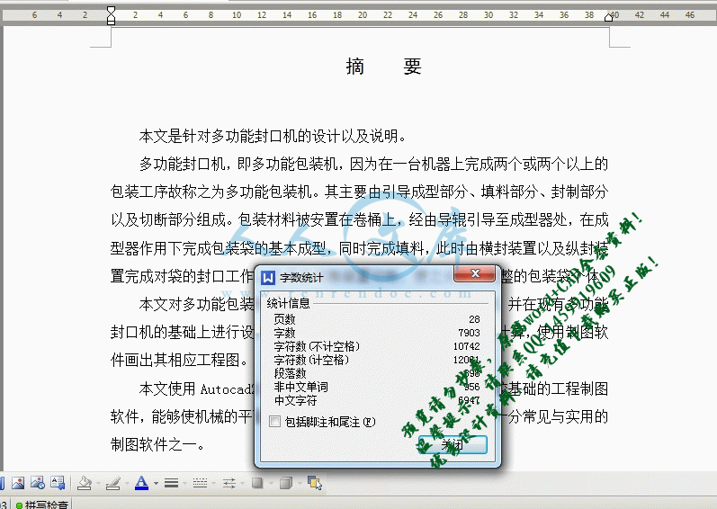
本文是针对多功能封口机的设计以及说明。

多功能封口机,即多功能包装机,因为在一台机器上完成两个或两个以上的包装工序故称之为多功能包装机。其主要由引导成型部分、填料部分、封制部分以及切断部分组成。包装材料被安置在卷桶上,经由导辊引导至成型器处,在成型器作用下完成包装袋的基本成型,同时完成填料,此时由横封装置以及纵封装置完成对袋的封口工作,之后由切断装置切断,使之分离为完整的包装袋个体。

本文对多功能包装机的工作原理、结构等做了分析及说明,并在现有多功能封口机的基础上进行设计,设计出一套可行的方案并进行相关计算,使用制图软件画出其相应工程图。

本文使用Autocad2010对其进行绘图,Autocad2010是比较基础的工程制图软件,能够使机械的平面结构简单、清晰地表现出来,是当下十分常见与实用的制图软件之一。

关键词:多功能封口机  包装  Autocad

Abstract

This paper is aimed at the multifunctional sealing machine design and description.

Multifunctional sealing machine, the multifunction packing machine, because the completion of two or more than two of the packaging process is called multifunction packing machine in a machine. It is mainly composed of lead forming part, filling, sealing and cutting part part part. Packaging materials are placed in the roll barrel, through the guide roller guide to forming device, the completion of the basic molding packing bag in the shaper, at the same time, filler, this time by the sealing device and longitudinal sealing device to complete sealing of the bag, then cut by the cutting device, so that the separation for the complete package bag of individual.

This paper makes analysis and description of the working principle, multi function packaging machine structure, and machine design based on the existing multifunctional sealing, designed for the relevant calculation a set of feasible solutions and, using the mapping software to draw the corresponding engineering drawings.

In this paper, Autocad2010 drawing of engineering drawing software, Autocad2010 is the basis of comparison, can make the plane mechanical structure simple, clearly demonstrated, is now very common and practical drawing software.

Keywords: Multifunctional sealing machine   sealing   Autocad

绪  论

1.1多功能封口机设计背景

封口机是典型的包装机械,包装机械在世界上已有一段历史。可以说,正因为有中国的造纸技术,才给纸包装技术的产生以及发展提供了必要条件,之后才得以由此发展出各种材料的包装机械。

从1850年始,世界的纸价格大幅跌落,纸张开始应用于食品包装。在这之后的1852年,美国的沃利发明出了纸袋制造机,由此正式出现了纸制品机械。1861年,德国人建立了世界上第一个包装机械工厂,并且在50年后也就是1911年成功生产出全自动成形充填封口机,这应该是有历史记载的最早的多功能封口机。

而中国在此方面由于各种原因起步晚于欧美各国,但经过了二十多年的发展,中国的包装机械已经成为国内机械工业十大行业之一,为中国的包装工业作出了重大贡献,满足了国内市场的基本需求,填补国内在此方面的空白,甚至出口国外。但是总体上看,中国包装机械的进出口额与发达国家相比仍然相去甚远,品种少,配套数量少,缺乏高精度以及大型化产品仍然是国内市场不可忽视的问题。而且国内此类产品主要以针对国外产品的仿制为主而缺少自主创新类产品,元器件的整体质量也不如国外,这就导致了包装产品的质量不如国外。

1.2设计目的与意义

本此设计的目的,在于对于多功能封口机的原理分析与结构设计,加深对于包装类机械的了解,能够在现有机械的基础上作出自己的一些设计,增强自我设计方面的能力,锻炼自身的相关能力。

由上文可知我国当前在包装机械上的成果并不如国外,因此,就更加需要我们对其产生重视,藉由对于多功能封口机的设计,进一步了解机械包装产业。

参考文献

[1] 卢立新 包装机械概论[M]中国轻工业出版社.2011

[2] 陈镜波 世界包装机生产与贸易概况[J]包装与食品机械.1995,第4期

[3] 孙恒 陈作模 葛文杰 机械原理第七版[M]高等教育出版社.2006

[4] 杨裕根 诸世敏 现代工程图学[M]北京邮电大学出版社.2008

[5] 濮良贵 纪名刚  机械设计第八版[M]高等教育出版社.2006

[6] 周林辉 软包装自动充填封口机的结构设计探讨[J]包装与食品机械 2005,第2期

[7] 杨军良 刘云霞 多功能忱型包装机横封传动机构设计探讨[J]包装与食品机械1999,第6期

[8] 张西良 式包装机工艺过程及其控制系统研究[J]轻工机械2003,第3期

[9] 戴远敬 袋成型包装机中常用拉膜机构分析[J]包装与食品机械 1999,第1期

[10] 孙建锋 桌上型全自动塑杯封口机的设计[J]包装与食品机械 2000,第6期

内容简介:
第六章多功能包装机 定义 在一台包装机上可以完成两个或两个以上包装工序的机器 这种机器常以它所能完成的包装工序联合命名 也有以其完成的主要功能命名的 多功能包装机分类 第一节概述 动画 第二节袋成型 充填 封口机 定义 用柔性材料制成的包装袋 将粉状 颗粒状 流体或半流体等物品装入其中 然后进行排气 或充气 封口 以完成产品包装的工艺过程 制袋用的柔性材料 如纸 蜡纸 塑料薄膜及其复合材料等 即有良好的保护物品的性能 又有质轻 价廉 易印刷 易成型封口 易开启使用 易被处理等特性 因而所制成的袋装产品轻巧 美观 体积小而受人喜爱 是软包装产品中的重要组成部分 其中尤以塑料薄膜及其复合材料的使用较广 发展最为迅速 特别六十年代以来 石油化学工业的高速发展 为软包装提供了丰富多样的柔性包装材料 再加上塑料薄膜具有独特的良好的热封性 印刷性 透明性 防潮防气性等 致使袋装软包装新产品更是层出不穷 内装物由最初的散粒体发展到胶体 液体 气体和大块状的固体 与此同时 也促进了袋装机不断地更新与发展 我国自六十年代初从国外引进样机 发展到近年来己能自己设计 制造多种袋装设备 一 袋成型 充填 封口机的包装工艺及类型 1 袋形扁平袋 适用于诸如奶粉 味精 洗衣粉等粉状和小颗粒产品的包装 自立袋 适用于饮料 牛奶 洗衣液等液体产品的包装 扁平袋 自立袋 2 袋成型 充填 封口机类型 根据包装机总体结构布局分 可分成立式与卧式两类 根据包装机运动形式可分为连续式和间歇式 目前连续式袋成型 充填 封口包装机在食品企业广为采用 立式可包装成的袋形主要为三面封口袋 四面封口袋 枕形袋 盒形袋等 较适应于流动性好的液体 半流体 粉体 颗粒状及小块状物料的包装 制袋过程中 一般先纵封 而后横封 四面封口袋型 二 立式袋成型 充填 封口机 一 工作原理 成卷包装材料薄膜1 经张紧导棍5 光电装置2 进入到成形器3中 被对折 由纵封拉膜辊11将两边薄膜加热加压封合成筒形 横封辊9压住底边加热封口 此时 经容杯式料盘6计量好的颗粒状食品被充入袋子中 横封辊9转开 袋子被纵封拉膜辊拉下 横封辊又转回加热加压封顶边 至此完成了全部封合工作 立式袋成型 充填 封口机可用于液体 半流体 粉体 颗粒状及小块状物料的包装 象鼻成型器制袋充填封口机1 卷筒薄膜 2 象鼻成型器 3 加料斗 4 纵封辊5 横封辊 6 固定切刀 7 回转切刀 动画 二 立式袋成型 充填 封口机工作原理与结构 1 立式 纵缝搭接 对接 袋成型 充填 封口机工作原理示意图 动画 动画 3 立式 三面封 袋成型 充填 封口机工作原理示意图 2 立式 四面封 袋成型 充填 封口机工作原理示意图 动画 4 尖顶角形袋制袋袋装机 与前面机型有许多相似之处 它是应用翻领式成型器制袋 薄膜经过成型器和四个均布的折痕滚轮 再经纵封器封合后成搭接圆筒状 料管下端部分由圆形截面变成方形截面 如图3 11所示折角板使两端收口 横封器横封上 下两道封口并切断 烫底器将自立袋底部烫成平底 三 卧式袋成型 充填 封口包装机 卧式袋成型 充填 封口机应用范围较广 主要用于块状物料的包装 如方便面 饼干 糕点 糖果 冰棒 雪糕等块状物品 该机包装袋形为枕形 一 包装工艺过程薄膜从卷筒上抽出后 经成型器 制袋器 将包装材料翻折成筒状 并把由进料带送来的物料裹在里面 经热封滚轮进行纵封 再通过封切刀具在两个包装物中间进行横封并切断 即完成一个包装 由出料带送出 卧式可包装成的袋形主要为枕形袋 也可包装成三面封口袋 纵缝搭接袋 纵缝对接袋 四面封口袋等 主要适应于块状物料的单件包装或组合包装 如饼干 面包 方便面等 卧式 枕式袋 袋成型 充填 封口机工作原理示意图 动画 卧式 多列 袋成型 充填 封口机工作原理示意图 动画 动画 卧式 旋转型 袋成型 充填 封口机工作原理示意图 卧式 四边封 袋成型 充填 封口机工作原理示意图 1 成形器 充填要求不同和包装袋型不同 制袋成型器区别很大 四 主要部件的结构 翻领式成型器 如图 a 所示平张薄膜拉过该成形器后就成搭接或对接圆筒状 在常用的几种成型器中 它的成形阻力较大 易使薄膜产生变形 使之发皱或撕裂 故对塑料薄膜适应性差 而对复合膜适应性较好 它常用于立式枕型制袋包装机上 包装粉状 颗料状物料 每种规格的成型器只能成型一种规格的袋宽 当袋宽规格发生变化时 就要更换相应尺寸的成型器 而且 成型器的设计 制造及调试都较复杂 象鼻式成型器 如图 b 所示 该成型器类似象鼻的形状 平张薄膜拉过该成型器时 薄膜变化较平缓 故成型的阻力比翻领成型器的阻力小 适用于塑料单膜的成型 它常用于立式连续三面封口制袋包装机及枕式对接制袋包装机上 但是 对制造同一尺寸的枕形袋所需对应的成型器 一个成型器只能成型同一宽度的袋形 象鼻成形器的结构尺寸比翻领式结构尺寸大 薄膜也易于跑偏 三角形成型器 如图 c 所示 由等腰锐角三角形板与平行导辊一起联结在基板上而成的 它是最简单的一种成型器 它具有一定的通用性 即能适应袋子的尺寸变化较大的需要 此时只要调节基板的上下位置即可 故此种成形器的适用范围广泛 不论立式 卧式 间歇运动或连续运动的三面 四面制袋包装机上都有应用 U形成型器 如图 d 所示 它是在三角形成器基础上改装而成的 薄膜在卷曲成型中受力状态比三角成型器好 其适应范围与三角形成型器一样 但其结构比较复杂 直角缺口导板式成型器 图3 15 e 所示 由缺口导板 导辊及纵封辊组成 将平张薄膜对开后又能自动对折封口成袋 薄膜成型时变形较大 多使用复合膜制袋 常用于立式连续包装机 从三角形 型及象鼻成型器可见 它们的共同特点是利用成型器外表面形状的变化而将平张薄膜折成对折或近似对折的形状 在平张薄膜逐渐变成对折状态的过程中 被一个个三角形图形所分割 1 直移型这类机型应用事先加工好的各种空袋 工作时 从袋库上每次取出一个袋 送给工序链夹持手 工序链带着空袋在各工位停歇时 完成各包装动作 图3 13所示为该机型的工艺路线示意图 给袋装置由真空吸头与供袋输送链组成 包装袋工序链上开口 闭口时 有特殊结构使每对夹持手相向运动 包装袋在两个工位上被加热封口 在后个工位上冷压定形 最后夹持手释放 产品下落入出料输送装置 第三节开袋 充填 封口机 直移式开袋充填封口机示意图1 储袋库 2 空袋输送链 3 开袋喷嘴 4 5 加料斗 块料粒 6 加料管 液体物料 7 8 封口器 9 冷确器 2 回转型这类机型是将包装空袋交给间歇回转工序盘 在工序盘停歇中 完成各包装工艺动作 图3 14所示的是能使包装袋内达到一定真空度的全自动真空袋装机工作示意图 空袋平放于纸斗内 靠第一组吸头在袋层上分出一只袋来 靠第二组吸头将袋吸着回转90 成直立状交给工序盘的夹持手 然后在各工位上停歇时依次完成打印 张袋装填物料 加入汤汁 预封 封口缝的部分长度 由机械手帮助转移入真空封口工序盘的真空室 在真空室内以抽真空后进行电热丝脉冲封口 冷却 最后真空解除 真空室打开 夹持手张开释放出包装成品来 回转式开袋充填封口机示意图1 储袋库 2 取袋吸嘴 3 上袋吸头 4 充填转盘 5 打印器 6 夹袋手 7 开袋吸头 8 加料管 9 加液管 10 预封器 11 送袋机械 12 真空密封转盘 13 第一级真空室 14 第二级真空室 15 热封室 16 17 冷却室 这类给袋式袋装机完成的袋装产品 可以是三面封口式 四面封口式自立袋 制袋用的材料主要是塑料薄膜与其它材料的复合材料 对于单层薄膜的袋 因取袋 供袋的困难而不能应用 综上所述 袋装机的机型较多 它们虽有外在差别 又有内在的联系 为便于研究 可对袋装机分类如下 按包装袋来源分 制袋式袋装机 给袋式袋装机 按总体布局分 立式或卧式袋装机 按运动形式分 连续或间歇运动的袋装机 直移或回转式袋装机 作业 1 简述袋成型 充填 封口机的定义 并比较立式和卧式袋成型 充填 封口机各自的应用范围 International Journal of Engineering and Technology Volume 2 No. 10, October, 2012 ISSN: 2049-3444 2012 IJET Publications UK. All rights reserved. 1717 An Inverse Kinematic Analysis of a Robotic Sealer Akinola A. Adeniyi 1, Abubakar Mohammed 2, Aladeniyi Kehinde 3 1Department of Mechanical Engineering, University of Ilorin, Ilorin, Nigeria 2Department of Mechanical Engineering, Federal University of Technology, Minna, Nigeria 3Department of Science Laboratory Technology, Rufus Giwa Polytechnic, Owo, Nigeria ABSTRACT A planar robotic sealing or brand stamping machine is presented for an automated factory line. The appropriate time to seal or to stamp an object is basically determined by a motor controller which relies critically on whether or not the object is in the best position. The extent of protraction and retraction of the piston head is largely dictated by an infrared sensor. Given the extent to protract or retract the piston head, the angular displacements of the link required are determined using the Inverse Kinematic (IK) techniques. The inertia and gravity effects of the links have been ignored to reduce the complexity of the equations and to demonstrate the technique. Keywords: Forward Kinematics, Inverse Kinematics, Robotics, Sealer. 1. INTRODUCTION An automated factory uses a number of mechanical links electronically controlled to achieve tasks. The benefits of factory automation are many and of strategic importance to management 1. Standard mechanical links are usually powered with electrical motors, pneumatic systems or solenoids. In a manually operated machine, the human performs visual checks and other standard checks that are to be replicated by automation. The interest of this work is centered on a hypothetical sealing machine which is used for stamping some signatures and logos as done in a branding factory line. Inverse kinematic analysis is applied to enable us determine angular displacements of the link. Kinematics involves the study of motion without consideration for the actuating forces. Inverse Kinematics (IK) is a method for determining the joint angles and desired position of the end-effectors given a desired goal to reach by the end effectors 1. A feasibility of using a PID controller was studied by Nagchaudhuri 2 for a slider crank mechanism but without an offset. Tolani et al 3 reviewed and grouped the techniques of solving inverse kinematics problems into seven. The techniques are the Newton-Raphsons method and its other variants. There are the Jacobian and the variants with pseudo-inverse (otherwise known as the Moore-Penrose inverse) for square or non-square Jacobian. Other methods are the control-theory based and the optimisation techniques. A number of authors 1, 4-7 have proposed algorithms for solving IK problems which include but not limited to Neural Network algorithm, Cyclic Coordinate Descent closure and Inexact strategy, but like every other techniques for a given problem the choice of method depends on the specifics of the problem. Buss 8 discussed the Jacobian transpose, the Moore-Penrose and the Damped Least Squares techniques. In terms of computational cost, the Jacobian transpose method is the cheap but can perform poorly based on the robot configurations. In this work the Jacobian transpose technique ill-performed but the Jacobian Inverse technique is suitable and more so it is a simple 2D planar representation of the problem with only 4 degrees of freedom. 2. OPERATIONS OF THE ROBOTIC LINK Fig. 1 shows the schematic diagram of the robotic sealing system. The capping or stamping is achieved with the piston or ram head, P. C is the conveyor line. The caps or the branding heads are placed in position and sensed by an infrared sensor, S. The instruction to seal or brand is dependent on feedback from the sensor. If the item to be branded, capped or stamped is out of place at the instance when the ram head was going to touch, the sensor feedback will be to retract the head. It can also be to not go too far. There can be a range of feedback to the motor controller, M. This kind of control system is similar to what a human operator would do if it were manually operated. The use of sensors and fast responding motor controller will make this hypothetical machine a very useful tool in a factory performing this kind of mundane task. This factory sub-line is a simple slider-crank mechanism with actuator arm A. In clearer terms, the instructions would be to press the piston ram to seal if the cap and the container are in line; to reverse the piston in case of a jam; to not press the piston ram if either the container or the cap is absent; to International Journal of Engineering and Technology (IJET) Volume 2 No. 10, October, 2012 ISSN: 2049-3444 2012 IJET Publications UK. All rights reserved. 1718 press further if the seal length is shorter than expected as may be caused by wear and tear. This clearly shows that the piston determines the angle of the link or the direction or action of the motor. This is an inverse kinematics problem. The sensor feedback part is much of a control engineering problem, not considered in this paper. Fig. 1: The robotic sealing rig schematic 3. ANALYSIS Fig. 2 is a representation of the slider-crank mechanism. There is an offset, f, of the piston axis from the motor axis, O1. O2 is the axis of the piston with moving coordinates (x,y). The motor rotates clockwise or counter clockwise about O1. If the crank makes displacement s on the piston plane, it is equivalent to a motion of ex and ey. This motion is caused by the crank making an angular motion clockwise or counter-clockwise, . The angle between the connecting rod and crank makes an angular displacement of, . This also means the angular shift of is made between the connecting rod and the piston or ram plane. Fig. 2: The offset slider crank (Cartesian coordinate world) In a computer game application for these, the angles would be explicitly required so that the links do not “physically disjoint”; for a physically connected link, the motor controller only would need the instruction to move only the crank. 3.1 The World Cartesian coordinate system is adopted. Clockwise is positive and motion to right and upwards are positive. The Top Dead Centre (TDC) is attained when the crank, radius r, and the connecting rod, length l, are in line. This is attained when . fm is the maximum variable offset based on the geometry. The Bottom Dead Centre (BDC) is reached when . The TDC and BDC with the variable offset are shown in Fig. 3. Fig. 3: The Top and Bottom Dead centre The piston has been constrained to move only in planar direction, on the vector of . In this work, the direction vector is , making the plane at 45o to the horizontal. 3.2 The Forward Kinematics The displacement caused by the motor moving clockwise from the position in Fig. 2 is represented in equation (1). Where subscripts (i,f) are respectively mean initial and final values. The position at f is reached in reality smoothly for a rotating crank, but the smoothness can be reached in fine incremental steps, in the numerical approach. At the end of the stepped increments, the final displacement to the goal is seen as a function of angular parameters given as: (1) The linear dependence of the angles, in this problem, can help to reduce the number of degrees of freedom to compute in equation (1). It can be shown that , thereby making . Using trigonometry, the instantaneous initial, arbitrary, position of the piston in Fig. 2 is given by Equation (2). (2) (3) The Jacobian matrix for is given in equation (4) and simplified to equation (5). International Journal of Engineering and Technology (IJET) Volume 2 No. 10, October, 2012 ISSN: 2049-3444 2012 IJET Publications UK. All rights reserved. 1719 J (4) J (5) Computing the new piston position involves solving equation (1). The new coordinate of the piston by the first term of expansion of the Taylor series can be shown to be given in equation (6). is the vector of the robot angular displacements for the related links. Mathematically, . Here, we have . Therefore the current position of the piston or the pressing head is approximately given in equation (6). It should be noted that can be measured from the horizontal to further reduce the equation sets, this is referred to as elsewhere in this paper. J (6) 3.3 Inverse Kinematics The problem is not that of solving for Xf given Xi and but it is that of solving for given Xi, and the desired Xf. This is iteratively implemented such that the target displacement of the piston is given as . This is a vector of the piston displacement and can be represented as . Since this is a planar problem with no displacements in the other directions, it reduces to a . To smoothen the possible jerk or jumpy effect, this can be stepped using a factor of which can be selected intuitively based on the ratio of r to L but and J is the inverse of Jacobian matrix. The algorithm checks if the target has been reached or not. Iteration is stopped when the solution is within a pre-determined level of error or a maximum number of iterations. The choice of these limiting values should depend on the response time acceptable. This can be critical for a real time application. J (7) 4. RESULT AND DISCUSSIONS Consider a current orientation of the robotic arm at any arbitrary position with the piston head at a position P1. Suppose the sensor system requires the piston to move to a target new position P2. The simulation is done for several arbitrary starting positions of the crank and results are similar for reachable targets. Supposing the crank angle is at a current orientation with crank angle of -5o, and there is an instruction from the sensor to retract the piston ram head by 0.1 times the crank arm length. The simulation instructs the crank proceeds to counter clockwise by 15.58o, this corresponds to an increase of to 19.26o and correspondingly, reduces to 86.32o. Fig. 4 shows the simulation progress of the piston head from a current position P1 to the new target P2 and the number of iterations done. Fig. 4: Crank Position and Iteration with the Jacobian Inverse Matrix The technique used is the Jacobian inverse technique. The Jacobian transpose technique is not predictable for the same problem and in this case, the solution settles to a local minimum for only one of the angles but the convergence rate is faster, see Fig. 5. Fig. 5: Crank Positions using the Inverse and Transpose of the Jacobian Matrix If there is a request to a physically unreachable target, such as to a more than the TDC or BDC locations, P3, the simulation runs and stops after the maximum number of iterations or if the Jacobian Matrix becomes un-invertible, Fig. 6. 0102030405060708090100-20-100Crank AnglePercent to TargetCrank Positions01020304050607080901000500010000Number of IterationsInternational Journal of Engineering and Technology (IJET) Volume 2 No. 10, October, 2012 ISSN: 2049-3444 2012 IJET Publications UK. All rights reserved. 1720 Fig. 6: Unreachable Target situation 5. CONCLUSION This paper is focused on the application of the Inverse Kinematics technique to the analysis of a robotic link, such as obtained in a sealer of an automated factory, without consideration for the effects of inertia effects. The Jacobian inverse technique, as mentioned in literatures, is more reliable in this application. The Jacobian transpose approach is not reliable. This paper has demonstrated the application of the inverse kinematics to a simple robotic sealer; the piston is instructed to retract by 0.1 units as a test case. The new crank angle was found more accurately with the Jacobian Inverse technique better that the Jacobian Transpose technique. The problem can be extended to include the dynamics for possible selection of the optimal driving torque or electric motor selection for the driving parts. REFERENCES 1 S. Tejomurtula and S. Kak, Inverse Kinematics in robotics using neural networks, Information Sciences, vol. 116, pp. 147-164, 1999. 2 A. Nagchaudhuri, Mechantronic Redesign of Slider Crank Mechanism, in ASME International Mechnical Engineering Congress & Exposition: IMECE2002, New Orleans, Louisiana, 2002. 3 D. Tolani, A. Goswami, and N. I. Badler, Real-Time Inverse Kinematics Techniques for Anthromorphic Limbs, Graphical Models, vol. 62, pp. 353-388, 2000. 4 S. K. Saha and W. O. Schiehlen, Recursive Kinematics and Dynamics for Parallel Structured Closed-Loop multibody Systems, Mechanics of Structures and Machines, vol. 29, pp. 143-175, 2007. 5 X. Wang, A behavior-based inverse kinematics algorithm to predict arm prehension postures for computer-aided ergonomic evaluation, Journal of Biomechanics, vol. 32, pp. 453-460, 1999. 6 A. C. Nearchou, Solving the inverse kinematics problem of redundant robots operating in complex environments via a modified genetic algorithm, Mechanism and Machine Theory, vol. 33, pp. 273-292, 1998. 7 M. J. D. Powell, Some Global Convergence Properties of a variable metric Algorithm for Minimization without Exact line searches, in Symposium in Applied Mathematics of the American Mathematical Society and the Society for Industrial and Applied Mathematics, New York City, 1976. 8 S. R. Buss, Introduction to Inverse Kinematics with Jocobian Transpose, Pseudoinverse and Damped Least Square methods, University of California, San Diego2009. 01002003004005006007008009001000-1000100Crank AnglePercent to TargetCrank Positi
温馨提示:
1: 本站所有资源如无特殊说明,都需要本地电脑安装OFFICE2007和PDF阅读器。图纸软件为CAD,CAXA,PROE,UG,SolidWorks等.压缩文件请下载最新的WinRAR软件解压。
2: 本站的文档不包含任何第三方提供的附件图纸等,如果需要附件,请联系上传者。文件的所有权益归上传用户所有。
3.本站RAR压缩包中若带图纸,网页内容里面会有图纸预览,若没有图纸预览就没有图纸。
4. 未经权益所有人同意不得将文件中的内容挪作商业或盈利用途。
5. 人人文库网仅提供信息存储空间,仅对用户上传内容的表现方式做保护处理,对用户上传分享的文档内容本身不做任何修改或编辑,并不能对任何下载内容负责。
6. 下载文件中如有侵权或不适当内容,请与我们联系,我们立即纠正。
7. 本站不保证下载资源的准确性、安全性和完整性, 同时也不承担用户因使用这些下载资源对自己和他人造成任何形式的伤害或损失。
提示  人人文库网所有资源均是用户自行上传分享,仅供网友学习交流,未经上传用户书面授权,请勿作他用。
关于本文
本文标题:多功能封口机的结构设计【优秀】【word+15张CAD图纸】
链接地址:https://www.renrendoc.com/p-316892.html

官方联系方式

2:不支持迅雷下载,请使用浏览器下载   
3:不支持QQ浏览器下载,请用其他浏览器   
4:下载后的文档和图纸-无水印   
5:文档经过压缩,下载后原文更清晰   
关于我们 - 网站声明 - 网站地图 - 资源地图 - 友情链接 - 网站客服 - 联系我们

网站客服QQ:2881952447     

copyright@ 2020-2025  renrendoc.com 人人文库版权所有   联系电话:400-852-1180

备案号:蜀ICP备2022000484号-2       经营许可证: 川B2-20220663       公网安备川公网安备: 51019002004831号

本站为文档C2C交易模式,即用户上传的文档直接被用户下载,本站只是中间服务平台,本站所有文档下载所得的收益归上传人(含作者)所有。人人文库网仅提供信息存储空间,仅对用户上传内容的表现方式做保护处理,对上载内容本身不做任何修改或编辑。若文档所含内容侵犯了您的版权或隐私,请立即通知人人文库网,我们立即给予删除!