说明书.doc

BJ4500越野车驱动桥设计【优秀汽车车辆类设计+3张CAD图纸】

收藏

压缩包内文档预览:(预览前20页/共62页)
预览图 预览图 预览图 预览图 预览图 预览图 预览图 预览图 预览图 预览图 预览图 预览图 预览图 预览图 预览图 预览图 预览图 预览图 预览图 预览图
编号:369476    类型:共享资源    大小:709.56KB    格式:RAR    上传时间:2014-12-06 上传人:QQ14****9609 IP属地:陕西
45
积分
关 键 词:
bj4500 越野车 驱动桥 汽车设计 汽车车辆 越野车驱动桥设计 汽车车辆类设计
资源描述:

BJ4500越野车后驱动桥的设计

BJ4500越野车驱动车桥设计

越野车驱动桥设计

BJ4500越野车驱动桥设计【优秀汽车车辆类设计+3张CAD图纸】

【带外文翻译+52页@正文14100字】【详情如下】【需要咨询购买全套设计请加QQ1459919609 】.bat

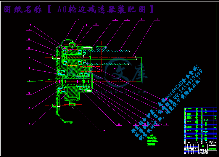
A0-轮边减速器装配图.dwg

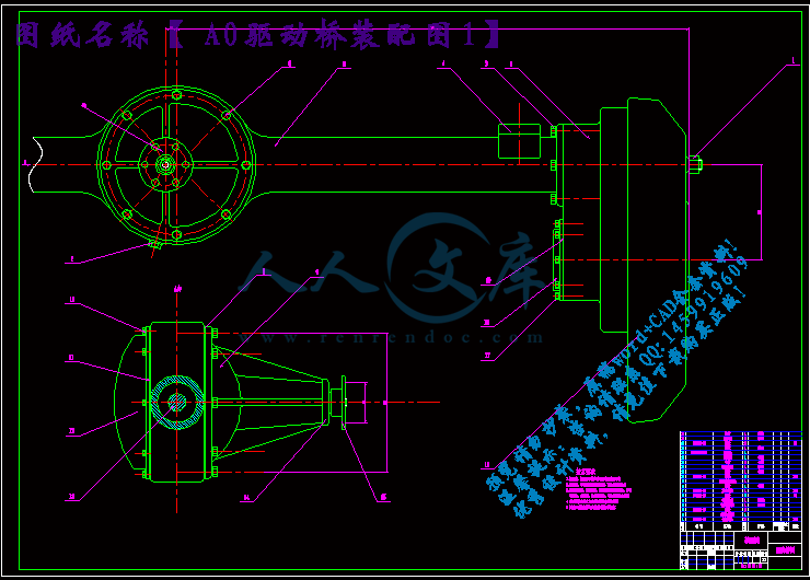
A0-驱动桥装配图1.dwg

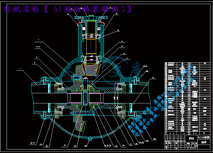
A1-驱动桥装配图2.dwg

任务书.doc

摘要目录.doc

说明书.doc

任务书

毕业设计(论文)题目: 越野车驱动桥设计                                

  立题的目的和意义:

为了进一步提高越野性能,并且减少单一传动副上的受力和高强度磨损,采用轮边减速器和主减速器共同应用的二级减速,可以大大提高其最小离地间隙,并且延长该车驱动桥及其零部件的使用寿命。目前汽车轮边减速器在国外的应用相对较多,但在国内尚处于起步阶段,汽车轮边减速器在我国仍有很大的发展潜力和发展空间,并且,轮边减速器在汽车上的应用将是未来重载汽车和越野车的发展方向。因此,汽车轮边减速器的设计和研究对于我们来说具有十分重要的意义。

  技术要求与主要内容:

1设计一个BJ4500越野车驱动车桥,提出一个完整的设计方案,画出装配图;

2.完成该车的驱动桥总体设计,或新增有关装置的选择与布置设计;

3.完成驱动桥的所有设计计算及校核;

4.独立完成A0图纸两张以上;

5.完成全面的设计论文。

摘要

本设计首先确定各主要部件的结构型式和主要设计参数,然后参考同类的驱动桥结构,确定出设计方案并进行计算和设计,最后对主从动锥齿轮、半轴齿轮、半轴、桥壳轮边机构等部分进行校核,对支撑轴承进行了寿命校核。

本设计采用主减速器和轮边减速器双级传动副传动,均匀分配单一传动副上的高强度磨损,轮边机构的应用,大大的提高了离地间隙,提高了汽车的通过性。本设计在我国尚处于起步阶段,在我国仍有很大的发展潜力和发展空间,本设计也将是未来越野汽车和重载汽车的发展方向。

本设计具有以下的优点:由于采用轮边双级驱动桥,使得整个后桥的结构简单,制造工艺简单,从而大大的降低了制造成本。并且,提高了汽车的离地间隙。

关键字:越野汽车;后桥;轮边双级;圆弧齿锥齿轮

Abstract

 This design is to first identify major parts of the structure and main design parameters, then reference to similar axles structure, confirmed the design and calculation and design, final master-slave dynamic bevel gear and half axle gears, half axle, bridge housing wheel edges institutions, to test the part such as back-up bearing life respectively. This design USES the main reducer and wheel edges reducer doublestage transmission vice transmission, evenly distributed single transmission of high intensity vice wear, wheel edges institutions of applications, greatly improve the ground clearance is achieved, improved the car through sexual.

This design in our country is still at the beginning, in our country still has great potential for growth and development space, this design also will be the future off-road vehicle and heavy-load automobiledevelopment direction.

 This design has the following advantages: due to the wheel edges doublestage axles, make the whole bridge structure is simple, make simple process, thus greatly reduce the production cost. And, improve the car from the ground clearance.

Key word: off-road vehicle, Rear axle, Wheel edges doublestage; Arc tooth wimble gear

目    录

摘要I

AbstractII

目    录III

第1章  绪论1

第2章  驱动桥总体结构方案分析2

第3章  主减速器设计4

3.1  主减速器的结构型式4

3.1.1  主减速器齿轮的类型4

3.1.2  主减速器主、从动锥齿的支承型式4

3.2 主减速器的基本参数与设计计算5

3.2.1  主减速比的确定5

3.2.2  主减速器齿轮计算载荷的确定5

3.2.3  主减速器齿轮基本参数的选择6

3.2.4  主减速器圆孤齿轮的几何参数计算7

3.2.5  主减速器圆弧锥齿轮的强度计算10

3.3  主减速器的材料选择及热处理方法12

3.4  主减速器轴承的计算12

3.4.1  锥齿轮齿面上的作用力12

3.4.2  主减速器轴承载荷的计算15

小结18

第4章  差速器设计19

4.1  差速器类型的选择19

4.2  差速器的设计和计算19

4.2.1  差速器齿轮的基本参数选择19

4.2.2  差速器齿轮的几何尺寸计算21

4.2.3  差速器齿轮的强度校核23

4.3  差速器齿轮的材料选择24

4.4  差速器壳体的材料选择24

小结24

第5章  驱动车轮的传动装置设计25

5.1  半轴的形式25

5.2  半轴的设计计算25

5.2.1  全浮式半轴的计算载荷确定25

5.2.2  全浮式半轴杆部直径初选26

5.2.3  半轴的强度计算26

5.2.4  半轴花键的强度计算27

5.3  半轴材料与热处理28

小结28

第6章  轮边部分的设计29

6.1  轮边减速器的结构型式29

6.1.1   轮边减速器的齿轮类型29

6.1.2  轮边减速器主、从动锥齿轮的支撑方式29

6.2  轮边减速器的基本参数与设计计算29

6.2.1  圆柱直齿轮主要参数的选择29

6.2.2  轮边减速器圆柱直齿轮的几何参考数计算30

6.2.3  轮边减速器圆柱齿轮的强度计算31

6.3  轮边减速器齿轮材料的选择及热处理方法34

6.4  轮边减速器壳的材料选择34

6.5  轮边减速器圆柱轴承的计算34

6.5.1  圆柱齿轮齿面上的作用力34

6.5.2  轮边减速器轴承载荷的计算36

小结38

第7章  驱动桥壳设计39

7.1  桥壳的结构型式39

7.2  桥壳的受力分析与强度计算39

7.2.1  桥壳的静弯曲应力计算39

7.2.2  在不平路面冲击载荷作用下的桥壳强度计算40

7.2.3  汽车以最大牵引力行驶时的桥壳强度计算41

7.2.4  汽车紧急制动时的桥壳强度计算43

7.2.5  汽车受最大侧向力时的桥壳强度计算43

7.3  桥壳的材料选择44

小结44

结论45

致谢46

参考文献47

附录48

第1章  绪论

汽车驱动桥位于传动系的未端。其基本功用首先是增扭、降速,改变转矩的传递方向,即增大由传动轴直接从变速器传来的转矩,并将转矩合理的分配给左右驱动车轮;其次,驱动桥还要承受作用于路在或车身之间的重直力,纵向力和横向力,以及制动力和反作用力等。驱动桥一般由主减速器,差速器,车轮传动装置和桥壳组成。

汽车的使用性能对传动系统有较高的要求,而驱动桥在传统中起着举足轻的作用。汽车的特点和优越性对于生产商来说提高其产品市场竞争力的一个法宝。对于越野汽车驱动桥的离地间隙来说,绝大多数汽车企业只是单纯的提高悬架和钢板弹簧的高度,这样做很大程度上降低了汽车的可靠性和安全性,然而轮边减速器驱动桥就可以解决这些问题,而且其优越性是无可比拟得,所以设计新型的驱动桥成为新的课题。

目前国外掌握轮边减速器技术核心的企业屈指可数,在国内更是聊聊无几,所以轮边减速器驱动桥的研究对于我们来说有举足轻重的意义。

设计后桥时应当满足如下基本要求:

1.选择适当的主减速比,以保证汽车具有最佳的动力性和燃油经济性。

2.外廓尺寸小,保证汽车具有足够的离地间隙,以满足通过性的要求。

3.齿轮及其他传动件工作平稳,噪声小。

4.在各种载荷和转速工况下有较高的传动效率。

5.具有足够的强度和刚度,减少不平路面的冲击载荷,提高汽车的平顺性。

6.制造容易,维修,调整方便。

第2章  驱动桥总体结构方案分析

本设计的课题是BJ4500后驱动桥,要设计这样的越野车驱动桥,一般选用非断开式结构,该种型式的驱动桥的桥壳是一根支承在左右驱动车轮的刚性空心梁,一般是铸造或钢板冲压而成,主减速器,差速器和半轴等所有传动件都装在其中,外接轮边部分。此时驱动桥,驱动车轮都属于簧下质量

驱动桥的结构形式有多种,基本形式有三种:

  1.中央单级减速驱动桥。

  2.中央双级驱动桥。

  3.中央单级、轮边减速驱动桥。轮边减速驱动桥较为广泛地用于油田、建筑工地、矿山等非公路车与军用车上。当前轮边减速桥可分为3类:一类为圆锥行星齿轮式轮边减速桥;一类为圆柱行星齿轮式轮边减速驱动桥;另一类是普通圆柱齿轮式轮边减速器。

  (1)圆锥行星齿轮式轮边减速桥。由圆锥行星齿轮式传动构成的轮边减速器,轮边减速比为固定值2,它一般均与中央单级桥组成为一系列。在该系列中,中央单级桥仍具有独立性,可单独使用,需要增大桥的输出转矩,使牵引力增大或速比增大时,可不改变中央主减速器而在两轴端加上圆锥行星齿轮式减速器即可变成双级桥。这类桥与中央双级减速桥的区别在于:降低半轴传递的转矩,把增大的转矩直接增加到两轴端的轮边减速器上 ,其“三化”程度较高。但这类桥因轮边减速比为固定值2,因此,中央主减速器的尺寸仍较大,一般用于公路、非公路军用车。

(2)圆柱行星齿轮式轮边减速桥。单排、齿圈固定式圆柱行星齿轮减速桥,一般减速比在3至4.2之间。由于轮边减速比大,因此,中央主减速器的速比一般均小于3,这样大锥齿轮就可取较小的直径,以保证重型卡车对离地问隙的要求。这类桥比单级减速器的质量大,价格也要贵些,而且轮穀内具有齿轮传动,长时间在公路上行驶会产生大量的热量而引起过热;因此,作为公路车用驱动桥,它不如中央单级减速桥。

(3)普通圆柱齿轮式轮边减速器。在双级主减速器中,通常把两级减速齿轮放在一个主减速器壳内,也可将第二级减速齿轮移向驱动车轮并靠近轮毂,作为轮边减速器。对于越野汽车来说,为了提高汽车驱动桥的离地间隙,可将普通的由一对圆柱齿轮构成的轮边减速器的主动齿轮置于其从动齿轮的垂直上方,这种布置方式的优点是结构紧凑、强度高、成本低,故广泛用于越野汽车上。

参考文献

1  刘惟信. 汽车车桥设计.北京:清华大学出版社,2004.

2  王望予. 汽车设计.    北京: 机械工业出版社,2004.

3  郭新华. 汽车构造. 2版. 北京: 高等教育出版社,2008.

4  朱孝录. 齿轮传动设计手册. 北京:化学工业出版社,2005.

5  廖念钊. 互换性与技术测量. 北京:中国计量出版社,2000.

6  戴少度. 材料力学. 北京:国防工业出版社,2002.

7  刘惟信. 汽车设计. 北京: 清华大学出版社, 2001.

8  陈家瑞. 汽车构造. 5版  北京:机械工业出版社,2006.

9  王黎钦. 机械设计. 4版  哈尔滨:哈尔滨工业大学出版社,2008.

10 王望予. 汽车设计. 4版  北京:机械工业出版社,2004.

11 王丽洁. 画法几何. 哈尔滨:哈尔滨工业大学出版社, 1998

12 汽车工程手册编辑委员会.汽车工程手册:设计篇.北京:人民交通出版

社,2001.

13 汽车工程手册编辑委员会.汽车工程手册:基础篇.北京:人民交通出版

社,2001.

14 Ford Motor Company Arup Gangopadhyay, Sam Asaro, Michael

Schroder,Ron Jensen and Jagadish Sorab. Fuel Economy

Improvement Through Frictional Loss  Reduction in Light Duty

Truck Rear Axle.SAE,2002.

15 Dirk Spindler  Georg von Petery  INA-Schaeffler KG. Angular

Contact Ball Bearings for a Rear Axle Differential.SAE ,2003.


内容简介:
哈尔滨工业大学华德应用技术学院毕业设计(论文) 题 目 越野车驱动桥设计 专 业 车辆工程 学 号 1079311104 学 生 李书涛 指 导 教 师 王聪 答 辩 日 期 2010年12月28日 哈工大华德学院哈工大华德学院毕业设计(论文)评语姓名: 李书涛 学号: 1079311104 专业: 车辆工程 毕业设计(论文)题目: 越野车驱动桥设计 工作起止日期:2010 年10 月10日起 2010年12月28 日止指导教师对毕业设计(论文)进行情况,完成质量及评分意见:_ 指导教师签字: 指导教师职称: 评阅人评阅意见:_ _ _ _ 评阅教师签字:_ 评阅教师职称:_答辩委员会评语:_根据毕业设计(论文)的材料和学生的答辩情况,答辩委员会作出如下评定:学生 毕业设计(论文)答辩成绩评定为: 对毕业设计(论文)的特殊评语:_ 答辩委员会主任(签字): 职称:_答辩委员会副主任(签字): 答辩委员会委员(签字):_ _ _ _ _ _ _ _ _ _ _ _ _ _ _年 月 日哈工大华德学院毕业设计(论文)任务书 姓 名:李书涛 院 (系):汽车工程系 专 业:车辆工程 班 号:0793111 任务起至日期: 2010 年 10 月 10 日至 2010 年 12 月 28 日 毕业设计(论文)题目: 越野车驱动桥设计 立题的目的和意义:为了进一步提高越野性能,并且减少单一传动副上的受力和高强度磨损,采用轮边减速器和主减速器共同应用的二级减速,可以大大提高其最小离地间隙,并且延长该车驱动桥及其零部件的使用寿命。目前汽车轮边减速器在国外的应用相对较多,但在国内尚处于起步阶段,汽车轮边减速器在我国仍有很大的发展潜力和发展空间,并且,轮边减速器在汽车上的应用将是未来重载汽车和越野车的发展方向。因此,汽车轮边减速器的设计和研究对于我们来说具有十分重要的意义。 技术要求与主要内容:1设计一个BJ4500越野车驱动车桥,提出一个完整的设计方案,画出装配图;2.完成该车的驱动桥总体设计,或新增有关装置的选择与布置设计;3.完成驱动桥的所有设计计算及校核;4.独立完成A0图纸两张以上;5.完成全面的设计论文。 进度安排:2010.10.10-2010.10.20 调研、资料收集、撰写开题报告2010.10.21-2010.11.10 方案设计、初步计算及草图绘制2010.11.11-2010.12.10 主要图纸工作及主题计算与说明说的撰写2010.12.11-2010.12.16 图纸及计算工作的修正,论文整理及完善,准备答辩2010.12.17-2010.12.28 答辩、提交毕业设计相关材料 同组设计者及分工:指导教师签字_ 年 月 日 系(教研室)主任意见: 系(教研室)主任签字_ 年 月 日哈尔滨工业大学华德应用技术学院毕业设计(论文)摘要本设计首先确定各主要部件的结构型式和主要设计参数,然后参考同类的驱动桥结构,确定出设计方案并进行计算和设计,最后对主从动锥齿轮、半轴齿轮、半轴、桥壳轮边机构等部分进行校核,对支撑轴承进行了寿命校核。本设计采用主减速器和轮边减速器双级传动副传动,均匀分配单一传动副上的高强度磨损,轮边机构的应用,大大的提高了离地间隙,提高了汽车的通过性。本设计在我国尚处于起步阶段,在我国仍有很大的发展潜力和发展空间,本设计也将是未来越野汽车和重载汽车的发展方向。本设计具有以下的优点:由于采用轮边双级驱动桥,使得整个后桥的结构简单,制造工艺简单,从而大大的降低了制造成本。并且,提高了汽车的离地间隙。关键字:越野汽车;后桥;轮边双级;圆弧齿锥齿轮 Abstract This design is to first identify major parts of the structure and main design parameters, then reference to similar axles structure, confirmed the design and calculation and design, final master-slave dynamic bevel gear and half axle gears, half axle, bridge housing wheel edges institutions, to test the part such as back-up bearing life respectively. This design USES the main reducer and wheel edges reducer doublestage transmission vice transmission, evenly distributed single transmission of high intensity vice wear, wheel edges institutions of applications, greatly improve the ground clearance is achieved, improved the car through sexual. This design in our country is still at the beginning, in our country still has great potential for growth and development space, this design also will be the future off-road vehicle and heavy-load automobiledevelopment direction. This design has the following advantages: due to the wheel edges doublestage axles, make the whole bridge structure is simple, make simple process, thus greatly reduce the production cost. And, improve the car from the ground clearance.Key word: off-road vehicle, Rear axle, Wheel edges doublestage; Arc tooth wimble gear目 录摘要IAbstractII目 录III第1章 绪论1第2章 驱动桥总体结构方案分析2第3章 主减速器设计43.1 主减速器的结构型式43.1.1 主减速器齿轮的类型43.1.2 主减速器主、从动锥齿的支承型式43.2 主减速器的基本参数与设计计算53.2.1 主减速比的确定53.2.2 主减速器齿轮计算载荷的确定53.2.3 主减速器齿轮基本参数的选择63.2.4 主减速器圆孤齿轮的几何参数计算73.2.5 主减速器圆弧锥齿轮的强度计算103.3 主减速器的材料选择及热处理方法123.4 主减速器轴承的计算123.4.1 锥齿轮齿面上的作用力123.4.2 主减速器轴承载荷的计算15小结18第4章 差速器设计194.1 差速器类型的选择194.2 差速器的设计和计算194.2.1 差速器齿轮的基本参数选择194.2.2 差速器齿轮的几何尺寸计算214.2.3 差速器齿轮的强度校核234.3 差速器齿轮的材料选择244.4 差速器壳体的材料选择24小结24第5章 驱动车轮的传动装置设计255.1 半轴的形式255.2 半轴的设计计算255.2.1 全浮式半轴的计算载荷确定255.2.2 全浮式半轴杆部直径初选265.2.3 半轴的强度计算265.2.4 半轴花键的强度计算275.3 半轴材料与热处理28小结28第6章 轮边部分的设计296.1 轮边减速器的结构型式296.1.1 轮边减速器的齿轮类型296.1.2 轮边减速器主、从动锥齿轮的支撑方式296.2 轮边减速器的基本参数与设计计算296.2.1 圆柱直齿轮主要参数的选择296.2.2 轮边减速器圆柱直齿轮的几何参考数计算306.2.3 轮边减速器圆柱齿轮的强度计算316.3 轮边减速器齿轮材料的选择及热处理方法346.4 轮边减速器壳的材料选择346.5 轮边减速器圆柱轴承的计算346.5.1 圆柱齿轮齿面上的作用力346.5.2 轮边减速器轴承载荷的计算36小结38第7章 驱动桥壳设计397.1 桥壳的结构型式397.2 桥壳的受力分析与强度计算397.2.1 桥壳的静弯曲应力计算397.2.2 在不平路面冲击载荷作用下的桥壳强度计算407.2.3 汽车以最大牵引力行驶时的桥壳强度计算417.2.4 汽车紧急制动时的桥壳强度计算437.2.5 汽车受最大侧向力时的桥壳强度计算437.3 桥壳的材料选择44小结44结论45致谢46参考文献47附录484附录Car driver bridge just common failure analysis and repair methods Motor reducer main function is to increase the input torque, lower speed, and will accept the transfer of power to change the direction of differential. Disassembly in the maintenance process, the main reducer assembly and adjustment of the quality of the good or bad, a direct impact on the main reducer of the state of technology and the main gear reducer, vice life. Must be in accordance with technical requirements and methods to ensure that the assembly quality and accuracy of the adjustment. Reducer in the main assembly in the process of adjustment, including the main owners, driven bevel gear bearing pre-adjustments, the main, driven cone-prints and meshing gears meshing space adjustments, and so on. Reducer in the main assembly adjustment, the adjustment in order to ensure the quality of assembly, must abide by the rules as follows: First, the first adjustment of the pre-bearings, and then adjust the gear mesh, vice-prints, the final adjustment of the meshing gears, deputy space. Secondly, the main, driven gear bearing cone of pre-degree must be provided for in the original methods and numerical check and adjust the main reducer in the process of adjustment, bearing the pre-degree change may not always be in line with the original Provides value. Third, to ensure the engagement of qualified prints on the premise of the adjustment of meshing gears, deputy space. Meshing and mesh-prints of the changes in the amount of space must be in compliance with technical requirements, otherwise it is necessary to replace the pair in pairs. Fourth, the adjustment process, such as bevel gear, bevel gear Aoli Kang and hypoid bevel gear, often moving to take the initiative to adjust the bevel gear mesh prints, driven by mobile bevel gear meshing space adjustments. The high-arc bevel gear Gleason bevel gear meshing and mesh-prints of the gap adjustment method is not special. Bearing reducer main pre-adjustments in order to remove the main, driven bevel gear shaft bearing the extra space axial and radial clearance, and reducer installed in the main, driven bevel gear shaft bearings, it should be a certain The pre-compression, and part of the balance before and after the axial load bearing. This will make the main, driven bevel gear at work to maintain the right mesh, and can pre-and post-bearings to obtain a more uniform wear. First of all, take the initiative to adjust the bevel gear bearing the pre-, pre-adjustment of their degrees in two ways: The first method is through changes in the gasket to adjust to adjust. Adjust the location of gaskets, and some separation between the two sets of bearings, some shaft in the shoulder, some in the back of the main reducer. Adjusted increase in the pads, reducing the pre-degree; pads to reduce the adjustment, increased pre-degrees. The second method is to use an alternate set of flexibility to adjust it by the installation, according to the provisions of torque tightening nut penetration margin of the fixed disk, so that every other set of elastic deformation resulting from the initiative to ensure the bevel gear bearing the pre-degrees. Next, adjust the bevel gear follower of the pre-degree bearing. According to the driver of the bridge structure is divided into two different ways: the first is a single-stage reducer, which is driven bevel gear differential bearing bearings, driven adjustment bevel gear bearing pre-degree differential bearing adjustment is pre - Tight, adjust the differential bearing on both sides of the nut adjustment to achieve. Adjustments on both sides of the nut tightened, pre-degree increase; on both sides of the adjustment screw pine nut, pre-degree decrease. The second is a two-stage reducer, the bevel gear driven secondary and take the initiative to slow down the cylindrical gear with a fixed axis, with both ends of the bearing shell on the main reducer. Adjust the location of gaskets in the two bearings between the shell and cover. Adjusted increase in the pads, reducing the pre-degree; pads to reduce the adjustment, increased pre-degrees. Second, the main, driven bevel gears meshing tooth prints and the adjustment of the main side of the gap, driven bevel gears meshing side of the gap-tooth-prints and adjustment: the main, be driven bevel gear teeth along the direction of the long exposure, and its location in the control gear The little-central bias, the small end-to-end from the Ministry of 2 7mm, traces of contact with the length of not less than 50% of the long teeth, tooth direction of the high-contact-prints should be not less than 50% of the high-gear, the general should be from the addendum 0 . 80 1.60mm; side of the tooth gap to 0. 15 0. 50mm, but each of the bevel gears meshing Vice change in the amount of space no larger than 0.15mm. When the owners, driven bevel gears meshing side of the gap-tooth-prints and do not meet the requirements should be adjusted in accordance with the following method to simplify the formula is: Progressive, that is, when the mating preference-prints big-time, move from gear to gear shift Near; at this time if the tooth side of the gap is too small, will take the initiative to move out of gear. From a small, that is, when the mating preference-prints little-time, move from gear to gear the initiative away; at this time if the tooth side of the gap is too large, the initiative will be moved closer to the gear inside. Lord jacking, that is, when the mating preference-prints addendum, the initiative will be moved closer to the driven gear to gear; at this time if the tooth side of the gap is too small, will be driven out of gear away. The main root out, that is, when the mating preference-prints root, it will take the initiative to gear since moving away gear; at this time if the tooth side of the gap is too large, driven gear will be moved closer to the inside. In the motor-driven mechanical automotive power train, drive power train bridge at the end of their basic function is to increase the transmission shaft or transmission came directly from the torque, torque will be allocated to the left and right wheel drive with Vehicle kinematics required by the differential function; at the same time, drivers also have to face the role of the bridge on the road or inside the frame and between the vertical, horizontal and vertical force. Therefore, vehicle drive axle should have the following functions: to ensure that the right has a reduction ratio, so that the car has the best power and fuel economy; differential with the role to ensure that the vehicle or to the uneven roads, tires do not have a Waterloo is delayed; have greater ground clearance in order to ensure the adoption of good; as much as possible to reduce weight in order to reduce vehicle weight; gear transmission and other mechanical work in a smooth, noise-free. Driver function as the bridge complex, so a higher failure rate. Its main fault: the early damage to the main reducer, made bridge-driven sound, heating and oil and so on. Bridge driver were the causes of the different and various fault is not the formation of a single isolated, but interrelated. If a failure occurred in a timely manner is not ruled out, it is easy to induce another failure to form a chain reaction. If the gap is too small mesh gear, it would drive axle fever, and it will lead to fat drive axle ring, but also the main cause of early damage to the reducer. Reducer is the main driver bridge in the heart of its early damage will seriously affect the life of the drive axle. Early in the form of its damage are: Vice-gear early wear, tooth fracture, early damage to the gear bearings and so on. Meshing gears are too small or too large gap caused by wear and tear in the early gears. Bearing the pre-force is too large or too small. Preload is too large, the impact on the efficiency of transmission so that the bearings overheat and shorten the life span; Preload over an hour to make the situation worse meshing of gears, contact stress increases, leading to a pair of early wear and tear. Not add gear oil requirements. Main reducer to be added as required gear oil in order to guarantee the normal lubrication of the gear, otherwise, in a very short car mileage, the tooth will be due to poor lubrication caused by pitting, and a sharp bond wear. Driven gear as a result of the adjustment locking nut loose and have a shift. Adjust the nut loose, causing a passive gear shift, the meshing gap change gear, Deputy Ambassador of early wear and tear. Common faults: 1. Tooth fracture. Meshing gears too much space. When the gear mesh in time to adjust without too much space, so that the owners, driven gear engagement in the process of impact, making gear fault. 2. Differential gear bearings or bearing damage. Bearing damage, roller out in the main reducer, the gear will be damaged. 3. Driven gear differential with the loose bolt connections, and off, also damaged gear. 4. Severely overloaded vehicle, so that the bearing load, making it lower life expectancy. Overloaded vehicle traveling through uneven pavement, gears and bearings, etc. impact on the load in a row and the role of the early damage occurred. In short, the judge ruled out and drive axle failure, it is necessary to analyze specific issues. In general, improper use, improper assembly adjustment, the quality of the parts itself is a question which drives the root causes of bridge failure. The fault has produced a number of reasons, or one; at the same time, adjustment of the assembly, such as using incompatible with a drive axle that could cause a variety of failures. 汽车驱动桥常见故障分析及维修方法汽车主减速器的功用是将输入的转矩增大,转速降低,并将接受的动力传递方向改变后传给差速器。在拆装维修过程中,主减速器装配与调整的质量好坏,直接影响着主减速器的技术状态和主减速器齿轮副的使用寿命。因此必须按照技术要求和方法步骤进行,以确保装配质量和调整精度。主减速器在装配过程中的调整主要包括主、从动圆锥齿轮轴承预紧度的调整,主、从动圆锥齿轮啮合印痕和啮合间隙的调整等。在对主减速器进行装配调整时为了保证装配调整质量,必须遵守以下调整规则:第一首先调整轴承的预紧度,再调整齿轮副的啮合印痕,最后调整齿轮副的啮合间隙。第二、主、从动圆锥齿轮轴承的预紧度必须按原厂规定的方法和数值进行检查与调整,在减速器调整过程中 ,轴承的预紧度不得变更,始终都应符合原厂规定值。第三、在保证啮合印痕合格的前提下 ,调整齿轮副的啮合间隙。啮合印痕和啮合间隙的变化量都必须符合技术条件,否则就要成对更换齿轮副。主减速器轴承预紧度的调整为了消除主、从动圆锥齿轮轴轴承的多余轴向间隙和径向间隙,在安装减速器和主、从动圆锥齿轮轴的轴承时 ,应使其具有一定的预紧力,进而平衡一部分前、后轴承的轴向负荷。这样即可使主、从动锥齿轮在工作时保持正确的啮合,又可使前、后轴承获得较为均匀的磨损。首先 ,调整主动锥齿轮轴承的预紧度,调整其预紧度有两种方法:第一种方法是通过增减调整垫片进行调整。调整垫片的位置 ,有的在两轴承之间隔套前,有的在轴肩前,有的在主减速器后面。增加调整垫片,预紧度减小;减少调整垫片,预紧度增大。第二种方法是用一个弹性隔套来调整,它靠安装时,按规定力矩拧紧突缘盘固定螺母,使隔套产生的弹性变形来保证主动锥齿轮轴承的预紧度。其次,调整从动锥齿轮轴承的预紧度。根据驱动桥的结构不同分为两种方法:第一种是单级减速器 ,其从动锥齿轮轴承就是差速器轴承,调整从动锥齿轮轴承预紧度就是调整差速器轴承的预紧度,靠调整差速器轴承两侧的调整螺母来实现。两侧的调整螺母拧紧,预紧度加大;两侧的调整螺母拧松,预紧度减小。第二种是双级减速器,
温馨提示:
1: 本站所有资源如无特殊说明,都需要本地电脑安装OFFICE2007和PDF阅读器。图纸软件为CAD,CAXA,PROE,UG,SolidWorks等.压缩文件请下载最新的WinRAR软件解压。
2: 本站的文档不包含任何第三方提供的附件图纸等,如果需要附件,请联系上传者。文件的所有权益归上传用户所有。
3.本站RAR压缩包中若带图纸,网页内容里面会有图纸预览,若没有图纸预览就没有图纸。
4. 未经权益所有人同意不得将文件中的内容挪作商业或盈利用途。
5. 人人文库网仅提供信息存储空间,仅对用户上传内容的表现方式做保护处理,对用户上传分享的文档内容本身不做任何修改或编辑,并不能对任何下载内容负责。
6. 下载文件中如有侵权或不适当内容,请与我们联系,我们立即纠正。
7. 本站不保证下载资源的准确性、安全性和完整性, 同时也不承担用户因使用这些下载资源对自己和他人造成任何形式的伤害或损失。
提示  人人文库网所有资源均是用户自行上传分享,仅供网友学习交流,未经上传用户书面授权,请勿作他用。
关于本文
本文标题:BJ4500越野车驱动桥设计【优秀汽车车辆类设计+3张CAD图纸】
链接地址:https://www.renrendoc.com/p-369476.html

官方联系方式

2:不支持迅雷下载,请使用浏览器下载   
3:不支持QQ浏览器下载,请用其他浏览器   
4:下载后的文档和图纸-无水印   
5:文档经过压缩,下载后原文更清晰   
关于我们 - 网站声明 - 网站地图 - 资源地图 - 友情链接 - 网站客服 - 联系我们

网站客服QQ:2881952447     

copyright@ 2020-2025  renrendoc.com 人人文库版权所有   联系电话:400-852-1180

备案号:蜀ICP备2022000484号-2       经营许可证: 川B2-20220663       公网安备川公网安备: 51019002004831号

本站为文档C2C交易模式,即用户上传的文档直接被用户下载,本站只是中间服务平台,本站所有文档下载所得的收益归上传人(含作者)所有。人人文库网仅提供信息存储空间,仅对用户上传内容的表现方式做保护处理,对上载内容本身不做任何修改或编辑。若文档所含内容侵犯了您的版权或隐私,请立即通知人人文库网,我们立即给予删除!