过程管理材料.doc

轻型载货汽车车架有限元静力学分析【汽车类】【1张CAD图纸】

收藏

压缩包内文档预览:
预览图 预览图 预览图 预览图 预览图
编号:403945    类型:共享资源    大小:2.26MB    格式:RAR    上传时间:2015-02-11 上传人:上*** IP属地:江苏
40
积分
关 键 词:
轻型 载货汽车 车架 有限元 静力学 分析 cad图纸
资源描述:

轻型载货汽车车架有限元静力学分析

93页 23000字数+说明书+任务书+开题报告+外文翻译+1张CAD图纸【详情如下】

任务书.doc

外文翻译--具有车架结构车辆的怠速震动分析.doc

封面.wps

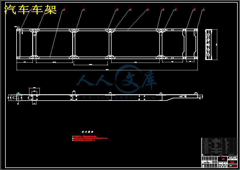
汽车车架.dwg

轻型载货汽车车架有限元静力学分析开题报告.doc

轻型载货汽车车架有限元静力学分析说明书.doc

过程管理封皮.doc

过程管理材料.doc

摘    要

汽车车架作为汽车总成重要的一部分,车辆受到来自道路和装载的各种复杂载荷最终都会传递给车架,并且汽车上许多重要总成都是以车架为载体,因而车架的强度和刚度在汽车总体设计中起了非常重要的作用。因此,车架结构性能的好坏关乎这整车设计的成败。若用传统经典力学方法计算,结果失真太大;而用试验法进行测试,成本高,周期长。为此本文采用了有限元分析技术,来实现车架结构设计合理化和轻量化的目的从而大大减少设计费用,缩短设计周期,同时提高设计工作的效率。因为,ANSYS在对实体模型分析上具有强大的功能,在结构静力学分析以及优化设计方面相比很多其他软件拥有十分明显的优越性。本文利用三维建模软件Pro/E和有限元分析软件ANSYS对某轻型载货汽车车架进行了Pro/E建模和ANSYS分析。通过对Pro/E和ANSYS软件的的了解和学习,采用Pro/E实体建模,导入ANSYS进行网格划分,应力加载,求解得出经动态分析结果,得出结论,之后可根据需要对已设计的实体单元为基础的车架结构进行拓扑优化模型和简单的尺寸优化模型,以车架的纵梁截面尺寸为设计变量,以车架结构的总体积最下为优化目标,对车架纵梁截面尺寸进行优化并分析优化结果。通过对初步设计出的轻型车架结构的实体建模及有限元分析,得到一些对车架设计有所帮助的结论,为今后车架的设计工作提供一定的指导作用。

关键词:轻型货车车架;三维建模;载荷;有限元静力学分析;模态分析

ABSTRACT

   Automobile frame,  as an important part of the vehicle, the vehicle being loaded from the road and the complex will eventually be passed to the load frame, and the car is the frame number of important general in Chengdu as the carrier, and thus the strength and the framestiffness of the overall design of the car plays a very important role.Therefore, the performance is good or bad frame structure about the success of this vehicle design.If the traditional method of classical mechanics, the result is too large distortion; and tested using test method, high cost and long period.To this end this paper, the finite element analysis, design of the frame structure to achieve the purpose of rationalization and lightweight thus reducing design costs and shorten design cycles, while improving the efficiency of design work.Because, ANSYS solid model in the analysis of powerful features in the structure of static analysis and design optimization software, compared with many other obvious advantages.In this paper, three-dimensional modeling software Pro / E and the finite element analysis software ANSYS, a light truck chassis is a Pro / E modeling and ANSYS.

   On Pro / E and ANSYS software, understanding and learning, the use of Pro / E solid modeling, meshing into ANSYS, the stress load, obtained by solving the dynamic analysis of the results, draw conclusions, and then as needed for. The solid element has been designed based on the topology optimization of frame structure model and the size of a simple optimization model to frame the longitudinal cross-section dimensions of design variables, the total volume of the frame structure to optimize the next goal, on the framelongitudinal section size optimization and analysis of optimization results.The preliminary design by a light frame structure of solid modeling and finite element analysis, get some help on the conclusions of the frame design, frame design for the future to provide some guidance.

Key words:Frame of track; Three-dimensional modeling; loads; Finite element static analysis; Modal  analysis                    

目  录

摘要I

AbstractII

第1章 绪论1

1.1 研究目的和意义1

1.2 车架国内外研究现状2

1.3 主要设计内容4

1.4 拟解决的主要问题5

第2章 轻型货车的车架设计6

2.1 车架的概述6

 2.1.1 车架的设计要求6

 2.1.2 车架的结构型式6

 2.1.3 纵梁、横梁及其联接10

 2.1.4 车架的制造工艺及材料11

2.2 车架的结构设计12

 2.2.1 车架设计参考12

 2.2.2 车架参数的确定13

 2.2.3 车架的弯矩及弯曲应力计算14

 2.2.4 车架的挠度计算16

2.3 本章小结18

第3章 车架三维模型的建立19

3.1 Pro/E软件介绍19

3.2 三维模型的建立20

3.3 本章小结24

第4章 车架有限元分析25

4.1 ANSYS的特点25

4.2 ANSYS的基本组成和功能26

4.3 Pro/E与ANSYS接口的创建28

4.4 车架有限元的静力分析30

 4.4.1 三维实体模型的网格划分30

 4.4.2 施加约束条件31

 4.4.3 车架4种工况分析32      

4.5 车架有限元的模态分析42

4.6 本章小结48

结论49

参考文献50

致谢51

1.1 研究目的和意义

在汽车制造市场竞争日益激烈的今天,汽车制造技术越来越先进,作为载货车主要承载结构的车架,它们的质量和结构形式直接影响车身的寿命和整车性能,如动力性、经济性、操纵稳定性。汽车的轻量化,就是在保证汽车的强度和安全性能的前提下,尽可能地降低汽车的整备质量,从而提高汽车的动力性,减少燃料消耗,降低排气污染。实验证明,汽车质量降低一半,燃料消耗也会降低将近一半。当前,由于环保和节能的需要,汽车的轻量化已经成为世界汽车发展的潮流。轻量化是21世纪整车发展趋势之一,减轻汽车质量意味着节约了能源和材料。车辆设计中,在满足载货车运营中对车架的刚度、强度及工艺改造等因素要求的同时,应当尽可能减轻它们的质量和降低制造成本。   综合分析这些文献可知,当前国内对于有限元法应用于车架结构分析的研究只是限于对车架和车架结构在静态扭转、弯曲载荷以及几种极限工况载荷作用下的分析,得出车架结构的静态应力分布,并对其进行了局部的修改,由于软硬件对计算模型规模的限制,模型的细化程度不够,因而结构的刚度、强度分析的结构还比较粗略,计算结构多用来进行结构的方案比较,离虚拟实验的要求还有相当大的差距。

1.3 主要设计内容

本课题通过参考国内外轻型载货车车架的结构及工作原理的基础上,对车架进行设计计算和校核,利用Pro/E建模并应用ANSYS软件对的车架进行有限元分析,具体工作如下。

结合某汽车公司生产实际要求,在参考以往的研究成果以及国内外发展的现状,确定主要研究内容。

   (1)研究应用弹性力学、有限元、静态分析、模态分析理论以及所有软件基础。

   (2)车架设计方法以及设计步骤的研究。

   (3)以某轻型货车车架为参考设计车架并对其进行PROE建模,将建成的PROE车架模型导入到ANSYS中准备进行有限元分析。

   (4)分析研究建立有限元模型要考虑的问题,比如结构的简化,单元的选取,单元数量的控制,单元质量的检查,网格的布局以及连接方式的模拟。

   (5)研究影响有限元分析结果的因素,比如单元厚度,单元大小,加强筋以及部件连接的模拟方法。

   (6)对车架有限元模型进行刚度强度分析、模态分析;找出车架结构中需要改进的部位,并依据分析结果提车改进方案。

   (7)对研究的车架进行惊呆性能评价。建立优化分析模型进行优化设计提出科学的改进方案。

1.4 拟解决的主要问题

   (1)如何设计车架基本结构

   (2)车架载荷及其约束的处理

   (3)静态工况下弯曲工况的分析处理

   (4)计算结果的处理

   (5)有限元模型的创建方法

   (6)对模型进行加载及求解的方法

   (7)对分析出的图形、数据的处理以及如何对车架进行优化

钢板经冷冲成形后,其疲劳强度要降低,静强度提高、延伸率小的材料的降低幅度更大。常用车架材料在冲压成形后的疲劳强度约为140~160MPa。

轿车车架纵梁、横梁的钢板厚度约为3.0~4.0mm,货车根据其装载质量的不同,轻、中型货车冲压纵梁的钢板厚度为5.0~7.0mm,重型货车冲压纵梁的钢板厚度为7.0~9.0mm。且槽形断面纵梁上、下翼缘的宽度尺寸约为其腹板高度尺寸的35%~40%[1]。

2.2 车架的结构设计

2.2.1 车架设计参考

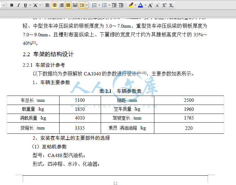
以下数据均为参照解放CA1040的参数进行设计[10-11],主要参数如表所示。

1、车辆主要参数

表2.1 车辆参数表

车总长 /mm5100轴距 /mm2500

载重量 /kg1850空车质量 /kg1960

满载质量 /kg4010驾驶室长 /mm1765

货箱长 /mm3335乘员 满油油箱 /kg220

2、安装在车架上的主要部件的选择

(1)发动机参数

型号:CA488型汽油机;

形式:四冲程、水冷、化油器;      

最大功率:65kw;

最大扭矩:157N·m;

外形尺寸(长宽高):659602671.5(mm);

质量:135kg。

(2)变速器参数

型号:CAS5-20A机械变速器;

中心距:85mm;

最大输出转矩:196N·m;

壳体长度:285mm;

静质量:铸铁壳体56kg。

  (3)货箱车头参数

货箱:钢板冲压货箱800kg;

车头:车头以及内部部件450kg。

  (4)钢板弹簧参数

车架上加装钢板弹簧,参数如表2.2所示。

表2.2 钢板弹簧

前钢板弹簧后钢板弹簧

作用长度 /mm12001300

片厚12-612-8

片宽 /mm7070

片数36

2.2.2 车架参数的确定

1、选取梯形车架,由两个纵梁与5根横梁铆接而成。其弯曲刚度较大,而当受扭矩时,各部分同时产生弯曲和扭转。其优点是便于安装车身、车箱和布置其他总成,易于汽车的改装和变形因此被广泛地用在载货汽车。车架全长等宽,取750mm。车架长度大致接近整车长度,约为轴距的1.4~1.7倍,取车架长度为4500mm,在纵梁的全长范围内具有相等的高度和宽度。纵、横梁均由5mm厚的16Mn钢板冲压而成(轻、中型货车冲压纵梁的钢板厚度为5~7mm。槽型断面纵梁上、下翼缘的宽度尺寸约为其腹板高度尺寸的35%~40%,纵梁槽形断面如图2.8所示。

结  论

本文运用有所学知识,根据资料对车架结构进行设计,同时运用有ANSYS对车架进行静态有限元分析。在现代有限元分析软件的支持下,在分析了车架结构力学特性的基础上建立了某载货车车架有限元模型,进行了车架静力分析,全面掌握了车架的应力分布情况,为车架的结构试验及其优化设计提供了良好的理论基础。通过本课题的研究,最终得出以下结论:

1、完成了车架结构设计,初步选择了车架结构形式、材料,同时经过计算得出该设计方案满足车架设计的所要求的刚度,挠度应在满足车架本身的刚度,挠度,在此基础上,可以利用ANSYS对已设计出的车架进行结构优化,使最终设计出来的车架在不影响使用性能的前提下,达到节省材料,结构轻量化的要求。

2、对载货车车架这类大型结构进行了有限元建模,采取了车架设计经常应用的单元类型,以及适当调整网格划分的精度,在不影响分析结果的前提下,使得设计求解时间更加快速,提高了车架设计和有限元分析工作的效率。

3、对于建模中经常出现的不能网格划分,以及模型边界,应力的问题,通过ANSYS中软件自动指出错误进行模型修改,另优设计分析更加快速精确,同时也了解了车架设计当中需要注意的问题,同时在设计中还可以在不影响车架分析结果的前提下,对车架模型进行当如ANSYS过程中的简化,使得加载分析过程更加快速,避免了不必要的操作。

参考文献

[1]刘惟信.汽车设计[M].北京:清华大学出版社,2006.1

[2]汽车车身结构与设计[M].北京:机械工业出版社

[3]余志生.汽车理论[M].北京:机械工业出版社,2010.1

[4]姜勇,张波.ANSYS7.0基础教程与实例详解[M].北京:中国水利水电出版社

[5]詹友刚.Pro/ENGINEER中文野火版4.0曲面设计教程[M].北京:机械工业出版社,2009.1

[6]刘坤,吴磊.ANSYS有限元方法精解[M].北京:国防工业出版社,2004.8

[7]段进,倪栋,王国业.ANSYS10.0结构分析从入门到精通[M].北京:兵器工业出版社,2006.10

[8]冯国胜.汽车车架结构参数的优化设计[J].计算结构力学及其应用.1994(2):218—220

[9]刘新田,黄虎,刘长虹等.基于有限元的汽车车架静态分析.上海工程技术大学学报,2007,6:112~116

[10]宋允祁,王中亭.解放CA1040系列轻型货车构造与维修[M].吉林科学技术出版社,1995.

[11]宋允祁.中国第一汽车集团公司汽车产品构造图册[M].人民交通出版社,2000.

[12]唐金松.简明机械设计手册[M].上海科学技术出版社,2000.

[13]成大先.机械设计手册[M].化工工业出版社,2001.1.

[14]文晁云,曹利钢,陈立伟,张晓宇.基于ANSYS的螺簧车架静态强度分析[J].机械设计与制造2009(6)

[15]牛跃文. 基于ANSYS的矿用汽车车架有限元模态分析[J].煤矿机械2007,28(4)

[16]谷安涛,常国振.汽车车架设计计算的有限元法[J].汽车技术.1977(6):54.65

[17]钟佩思,赵丹,孙雪颜,魏群.基于ANSYS的汽车车架的建模与模态分析[j],机械设计与制造,2008(6)

[18]尹辉俊,志林.沈光烈货车车架的有限元分析[J]械设计 2005(11)

[19]安晓卫.马星国.祝宝发汽车车架的有限元模态分析[J], 沈阳工业学院学报1999

[20]Hassani B,Hinton E.A review ofhomogenization and topologyoptimization I-homogenization theory formedia、衍th periodicstructure[J].Computers and Structures.1998.69:707-717.

内容简介:
毕业设计(论文)任务书学生姓名系部汽车与交通工程学院专业、班级车辆工程07- 班指导教师姓名石美玉职称教授从事专业车辆工程是否外聘是否题目名称轻型载货汽车车架有限元静力学分析一、设计(论文)目的、意义汽车作为交通运输工具之一,在人们的日常生活中发挥着非常重要的作用。随着国民经济的快速发展,汽车工业也得到了飞速发展,在现代化发展的今天,生产出结构轻、性能好、质量高、用途广、安全可靠的汽车,成为了汽车厂家和客户共同关注的焦点。作为汽车总成的一部分,车架承受着来自道路及各种复杂载荷的作用,而且汽车上许多重要总成都是以车架为载体,因此设计出重量轻而各方面性能达到要求的车架结构是一项重要的工作。传统的车架结构设计是采用类比的思想进行经验设计,设计出的车架结构除了个别部位的应力水平较高外,大部分部位的应力水平较低。因此,有必要采用有限元法对车架结构进行优化设计,以降低车架的重量,减小汽车的制造成本,提高市场竞争力。 在汽车行业中,有限元法广泛应用于各大汽车总成,包括车架、车身、车桥、离合器、轮胎、壳体等零部件以及驾驶室噪声的分析,大大提高了汽车的设计水平,正在成为设计计算的强有力工具之一。目前,在进行汽车车架设计时,设计人员主要采用的还是传统的办法对车架进行简化的计算,或者由其它部门进行有限元分析计算。车架的这种设计模式导致的问题包括两个方面:一是车架简化计算精度不够,为保证强度及刚度要求而使车架的设计过于安全,造成设计出的车架结构过重,增加了设计成本;二是造成车架的设计与计算分离,不利于提高车架设计人员的设计水平。为了促进车架设计水平的提高,保证整车在市场上的竞争能力,必须将车架有限元分析技术提高到战略的高度上来。二、设计(论文)内容、技术要求(研究方法)设计内容:1.选题的背景、目的及意义;2.Pro/E、ANSYS软件研究;3.车架设计的方法步骤研究;4.用Pro/E软件建立车架整体模型,然后导入ANSYS软件进行网络划分;5.假定汽车满载情况下,对车架进行弯曲、扭转、紧急刹车、急转弯四种工况下的受力和变形情况的静态有限元分析。技术要求:1.研究轻型载货汽车车架;2.有限元模型、载荷建立正确;3.生产纲领:成批生产。三、设计(论文)完成后应提交的成果轻型载货汽车车架有限元静力学分析程序一份;设计说明书(20000字以上)一份。四、设计(论文)进度安排(1)知识准备、调研、收集资料、完成开题报告 第12周(2.283.11)(2) 整理资料、提出问题、撰写设计说明书草稿、熟悉Pro/E、ANSYS软件的使用 第35周(3.144.1)(3)理论联系实际分析问题、解决问题,使用Pro/E、ANSYS软件完成中型载货汽车车架的三维设计、强度分析等部分设计内容,中期检查 第68周(4.44.22)(4)改进完成设计,改进完成设计说明书,指导教师审核,学生修改 第912周(4.255.20)(5)评阅教师评阅、学生修改 第13周(5.235.27) (6)毕业设计预答辩 第14周(5.306.3)(7)毕业设计修改 第1516周(6.66.17)(8)毕业设计答辩 第17周(6.206.24)五、主要参考资料1.刘惟信汽车设计北京:清华大学出版社2.张洪信有限元基础理论与ANSYS应用北京:机械工业出版社,2006.13.段进,倪栋,王国业ANSYS10.0结构分析从入门到精通北京:兵器工业出版社,2006.104.姜勇,张波ANSYS7.0实例精解北京:清华大学出版社5.汽车车身结构与设计北京:机械工业出版社6.余传文重型载货汽车车架结构的有限元仿真及优化吉林大学硕士学位论文,20057.黄华,茹丽妙重型运输车车架动力学分析车辆与动力技术8.刘新田,黄虎,刘长虹等基于有限元的汽车车架静态分析上海工程技术大学学报,2007,6:1121169.轻型载货汽车车架设计资料10.网络资源,超星数字图书馆11.近几年相关专业CNKI网络期刊等六、备注指导教师签字:年 月 日教研室主任签字: 年 月 日附录附录AAn Analysis of Idling Vibration for a Frame Structured VehicleABSTRACTA finite element model for an entire frame-structured sports utility vehicle was made to evaluate the characteristics of the idling vibrations for the vehicle. The engine exciting forces were determined by Soumas method to simulate the idling vibrations. The modeling of the power plant and the entire vehicle was verified by the reasonable agreement of the experiment and calculation results. Attention was focused on the frequency of the first-order vertical bending mode for the frame. It has become clear that the idling vibration level of the vehicle is lowered by decreasing the frequency of the first-order frame bending mode.INTRODUCTION One of the defects of a diesel vehicle, which has fuel and economical efficiency, is idling vibration for a vehicle body. In a diesel engine, sharp pressure rise caused by the generation of the thermal energy affects the pistons. In the crank system, which converts the linear motion into the rotary motion, two types of reaction forces excite the engine block: the reaction caused by the alternation of the velocity vector in each moving parts, and by the non-uniform rotary motion generated by the finite number of cylinders. The forces transmit to an engine block, an engine foot, a rubber engine mount, a frame, a rubber cab-mount, and then a vehicle body, which make occupants uncomfortable. The idling vibration for large-sized commercial vehicles was estimated at the early development stage, and the measures against the vibration were taken by simulating the engine exciting forces with Soumas method,and entering them to a vehicle model. In this paper, the idling vibration was determined by entering the engine exciting forces to the vehicle model, which was made of the finite element of the frame and the body for a small-sized recreational vehicle (RV). Also in this paper, how the natural modes for the frame changes in the vehicle condition is analyzed, and it was indicated that the natural frequency of the first-order vertical bending for the frame had a significant effect.ANALYSIS OF THE VEHICLE BODY VIBRATIONFigure 1 shows the results of analyzing the frequencies of the acceleration in vertical vibration generated on the seat rail while idling in small-sized RV powered by 4-cylinder diesel engine. The main part of the idling vibration is the second-order engine rotation. The 0.5th, 1st, and 1.5th -orders are also critical. However, these orders are caused by the varied combustion between cylinders. A measure against the varied combustion can be expected by improving the injection system. In this research, only 24Hz of the second-order at the idling rotation speed of 720rpm is focused on as a measure in the vehicle structure. Besides, a measure for lowering the vibration is studied because the vertical vibration on seats has a great damaging effect on human sense.IDENTIFICATION OF THE ENGINE EXCITING FORCEThere are three paths for the engine to excite vibration to a vehicle body: through an engine mount, a driving system, and a tail pipe. In this paper, the path through an engine mount, which has a greatest effect, is studied. The various types of methods to identify the exciting force through an engine mount are known. In this paper, Soumas method is used.OUTLINE OF SOUMAS METHODThe cause of the exciting force to an engine block in the controversial frequency domain of the idling vibration is considered. First, the combustion pressure that acts on the pistons is considered to cause the vibration. However, assuming that a piston crankshaft does not move with a flywheel and an engine block fixed in some way, the engine components are supposed to be completely rigid in this frequency domain. In this situation, the engine block will not vibrate if the piston crankshaft does not move in spite of the rapid pressure rise in a combustion chamber due to the diesel combustion.Accordingly, the direct cause of the engine block vibration is not the combustion pressure but the reaction against the piston crankshaft movement. To determine the exciting force to the engine block, the reaction forces against the movement of the mass (mainly in crank system and piston system), which works inside and outside of the engine block, may be calculated.In Soumas method, the non-uniform rotary motion in the crank system is found by measuring the pulse generated in a ring gear of the flywheel. Then, the vertical motion in the connected piston system is calculated to determine the exciting force to the engine block using each mass specification value.VERIFICATION OF THE ACCURACY IN THE EXCITING FORCEThe exciting forces are added at the point corresponding to the crankshaft on the entire vehicle model (described later). The vibration on the head cover and the right engine foot, which the exciting forces mostly affect, is estimated. The results of comparing the calculation with the experiment are shown in Figure 2 and 3. In Figure 2 and 3, 5 types of calculated results are shown considering the idling rotation speed changes.In Figure 2 and 3, the calculation and the experiment are identified around 24 Hz, 48 Hz, and 72 Hz of 2nd, 4th, and 6th-orders at the speed of 720 rpm. The data of the left engine foot, which is not shown in this paper, is also almost identified. In this frequency domain, as for the vibration, the engine and the vehicle body are insulated by the engine mount. The body hardly affects the engine vibration. As the data of the experiment and the calculation is identified in this domain, the power plant modeling and the exciting force can be considered reasonable.However, around 12 Hz of 1st-orders, data is not much identified. In this frequency domain, the vibration of the engine and the vehicle body are mutually coupled through the engine mount. Therefore, the accuracy of the vehicle body model has a damaging effect.IMPROVEMENT OF THE MEASURING ACCURACY IN LOW-FREQUENCY VIBRATIONThe engine exciting force was determined using Soumas method, and the vibration in each part of the engine was calculated by adding the exciting force. So far, however, the calculated data has not been much identified with the actual measurement. Therefore, the accuracy of the actual measurement is improved. In the surface vibration of the engine, the low-frequency vibration, which causes the idling vibration, and the high-frequency vibration, which causes noise, are mixed. When the mixed vibration is measured with a piezo element acceleration pickup, the high-frequency order is emphasized and the target low-frequency order becomes relatively small. For example, the measured acceleration to time waveform for the vertical vibration in the right engine foot is shown in Figure 4. In this paper, a strain gage acceleration pickup, which measures force acting on the inner weight by strain, is used. This device, which is larger than a piezo element acceleration pickup, is more sensitive to the acceleration. Besides, silicon oil is filled inside to protect the detecting parts in this device, which mechanically blocks off the high-frequency order. The measured acceleration to time waveform for the vertical vibration with the device is shown in Figure 5. Compared with Figure 4, Figure 5 shows only the low-frequency order although the same area was measured. In this way, the high-frequency order is blocked off, which results in the higher sensitivity with the device. This time, the device, which measures the acceleration ranging from 0 to 20m/s2,was used. This device is easily calibrated using G-forces because it has the higher sensitivity. When a piezo element acceleration pickup was used, the differences between the calculation and the experiment were 20-40% in the main order of the vibration, and a few times in other orders. Therefore, the principle of Soumas method using a piezo element acceleration pickup has been in doubt. However, the data of the experiment and the calculation has been identified as shown in Figure 2 and 3 since a strain gage acceleration pickup, which has been used in the experiment of movement performance, was used for an engine.Fig. 1 Seat rail vertical vibration Fig. 2 Head cover lateral vibrationFig. 3 Right engine foot vertical vibration Fig.4 Measurement with piezo element acceleration pickupENTIRE VEHICLE MODELFigure 6 shows the body model. Interior and exterior equipments such as doors and seat are added in the form of 85 mass points to the main structure modeling detailed with sheet metal finite elements. The grid points are 61,912. Figure 7 shows the model where a frame, a suspension, and an engine are combined, and a fuel tank and a bumper is added in the form of concentrated mass. The grid points are 39,262.Combining the models shown in Figure 6 and 7 using cabmount makes the entire vehicle model. Total grid points mounts to 101,174. The calculation time is 3,293 seconds using IBMSP2, MSC/NASTRAN Version 70.5.2. The calculating method is package calculation. If the model becomes on larger scale, the model must be calculated by the block structure.Figure 8 shows the frequency response function, indicating the responses of the frame with the right back engine mount after exciting the drivers seat rail. In the frequency ranging from 20 to 30 Hz, which is required for the analysis, the data of the experiment is qualitatively identified with that of the calculation.Fig. 5 Measurement with strain gage acceleration pickup Fig. 6 Body modeFig.7 Frame,power plant and suspension model Fig.8 Frequency response functionCORRELATION ANALYSIS OF THE MODESFrom the viewpoint of vibration characteristics, it can be considered that an entire vehicle is insulated by the engine mount and the cabmount, which have relatively small spring constants, although the insulation is not complete. When the entire vehicle is divided into block structures by each insulating mount and suspension, the body has 4 block structures:(1) Block where interior equipment is added in the form of concentrated mass to the body as shown in Figure 6, which is described as “body”, hereafter.(2) Block where the fuel tank and the bumper are added in the from of concentrated mass to the frame as shown in Figure 7, which is described as “frame,” hereafter. (3) Power plant (4) SuspensionAmong the above block structures, (1) body and (2) frame have the natural frequency around 24 Hz in the idling vibration. The vibration characteristics for the body, the frame and the entire vehicle model are compared and investigated.COMPARISON OF NATURAL FREQUENCYFigure 9 shows the distribution of the natural vibration frequency in each block structure and in the vehicle condition. The frame has 17 natural modes below 50Hz. In Figure 7, the model mounting a power plant and a suspension on the frame, is called Y chassis, which has 35 natural modes below 50 Hz. Y chassis makes the entire vehicle model by mounting the body, which has 94 natural modes below 50 Hz.When the number of natural modes of Y chassis is added to 61 natural modes of the body, total number of the modes amounts to 96. The number of the natural modes of the entire vehicle model (94) is less than the above total number by 2 modes. This is because 2 natural modes became above 50 Hz by combining Y chassis and the body, as the result of analyzing the mode correlation described later.Fig. 9 Natural modes in frequency domain附录B具有车架结构车辆的怠速震动分析摘要建立全车架结构SUV的有限元模型,用来评价车辆的怠速震动特性。用Souma理论确定发动机的动力来模拟怠速震动。发动机和整车的模型通过实验和计算结果协调以后共同决定。注意力放在了车架一阶纵向弯曲模型的频率上。降低一阶车架弯曲模型的频率可以减少车辆的怠速震动已经变得明确。简介具有燃油经济性的柴油车的一个缺点就是车身的怠速震动。在柴油发动机里,由热能积聚引起的压力急剧上升会影响活塞。在把直线运动转换成旋转运动的曲轴系统里,有两种反作用力使得发动机体振动:由移动部件运动换向引起的反作用力,和有限的气缸不均匀的转动引起的。这个力传递到发动机机体,发动机底部,橡胶的发动机支座,车架,橡胶驾驶室支架,最后到车身,引起乘客不舒服。大型商用车的怠速震动的平复处于发展的初期,用Souma理论模拟发动机震动,然后建立模型。这篇论文中,将发动机置于车中来确定怠速震动,因为车架和车身的有限元被当做一个小型休闲车。另外,在这篇文章中,也分析了车辆车架自然模式如何改变,并且指出车架一阶纵向弯曲的自然频率具有重要的影响。车身震动的分析图A1显示了四缸柴油机RV怠速过程中座椅扶手处采集的加速过程中纵向震动频率的分析。怠速震动的主要部分是二阶发动机转动,第0.5,第1,和第1.5阶同样重要。但是,这些不同是由于不同气缸的燃烧不同而引起的。完善喷射系统可以解决燃烧的差异。在这个实验中,只集中研究怠速转速是720rmp时24Hz车架的二阶震动。此外,也研究了降低振动的措施,因为座椅的纵向振动对人类的感觉有很大的破坏性影响。发动机引起作用力的判定发动机将振动传递给车身的路线有三种:通过发动机支座,驱动系统,和尾气排放管。在这篇论文中,研究了起主要作用的发动机支座的路线。研究方法有很多种,这里用Souma理论。Souma理论的概要考虑引起发动机集体受力的有争议的怠速振动频率范围。首先,作用在活塞上的燃烧压力被认为引起这个振动。但是,假设活塞曲轴并不随飞轮移动并且机体以某种方式固定,在这个频率范围发动机的零件被认为是完全刚性的。在这种情况下,如果活塞曲轴不移动,发动机机体就不会振动,尽管柴油燃烧引起压力的迅速上升。相应地,引起发动机机体振动的直接原因不是燃烧压力,而是活塞曲轴运动的反作用力。为了确定作用在发动机机体上的这个力,需要计算在机体内外都发挥作用的反作用力。在Souma理论里,通过测量在飞轮齿圈上收集到的脉冲来发现曲轴系统的不协调旋转运动。然后计算相连的活塞系统的纵向运动来确定发动机机体上的作用力。作用力准确性的验证在整车模型里(后续描述),振动力的增加和曲轴是对应的。评估振动主要影响的引擎盖和发动机右侧底部。计算数据和实验结果的比较结论在图A2和图A3中表示了出来。在图A2和图A3中,表示出来5种不同的计算结果,因为要考虑怠速转
温馨提示:
1: 本站所有资源如无特殊说明,都需要本地电脑安装OFFICE2007和PDF阅读器。图纸软件为CAD,CAXA,PROE,UG,SolidWorks等.压缩文件请下载最新的WinRAR软件解压。
2: 本站的文档不包含任何第三方提供的附件图纸等,如果需要附件,请联系上传者。文件的所有权益归上传用户所有。
3.本站RAR压缩包中若带图纸,网页内容里面会有图纸预览,若没有图纸预览就没有图纸。
4. 未经权益所有人同意不得将文件中的内容挪作商业或盈利用途。
5. 人人文库网仅提供信息存储空间,仅对用户上传内容的表现方式做保护处理,对用户上传分享的文档内容本身不做任何修改或编辑,并不能对任何下载内容负责。
6. 下载文件中如有侵权或不适当内容,请与我们联系,我们立即纠正。
7. 本站不保证下载资源的准确性、安全性和完整性, 同时也不承担用户因使用这些下载资源对自己和他人造成任何形式的伤害或损失。
提示  人人文库网所有资源均是用户自行上传分享,仅供网友学习交流,未经上传用户书面授权,请勿作他用。
关于本文
本文标题:轻型载货汽车车架有限元静力学分析【汽车类】【1张CAD图纸】
链接地址:https://www.renrendoc.com/p-403945.html

官方联系方式

2:不支持迅雷下载,请使用浏览器下载   
3:不支持QQ浏览器下载,请用其他浏览器   
4:下载后的文档和图纸-无水印   
5:文档经过压缩,下载后原文更清晰   
关于我们 - 网站声明 - 网站地图 - 资源地图 - 友情链接 - 网站客服 - 联系我们

网站客服QQ:2881952447     

copyright@ 2020-2025  renrendoc.com 人人文库版权所有   联系电话:400-852-1180

备案号:蜀ICP备2022000484号-2       经营许可证: 川B2-20220663       公网安备川公网安备: 51019002004831号

本站为文档C2C交易模式,即用户上传的文档直接被用户下载,本站只是中间服务平台,本站所有文档下载所得的收益归上传人(含作者)所有。人人文库网仅提供信息存储空间,仅对用户上传内容的表现方式做保护处理,对上载内容本身不做任何修改或编辑。若文档所含内容侵犯了您的版权或隐私,请立即通知人人文库网,我们立即给予删除!