连续式洗米机设计【任务书+翻译】【4张图纸】【优秀】
收藏
资源目录

压缩包内文档预览:
编号:423744
类型:共享资源
大小:2.18MB
格式:RAR
上传时间:2015-04-09
上传人:上***
认证信息
个人认证
高**(实名认证)
江苏
IP属地:江苏
39
积分
- 关 键 词:
-
连续式
洗米机
设计
任务书
翻译
图纸
连续式洗米机
- 资源描述:
-
连续式洗米机设计
81页 18000字数+说明书+任务书+外文翻译+4张CAD图纸【详情如下】
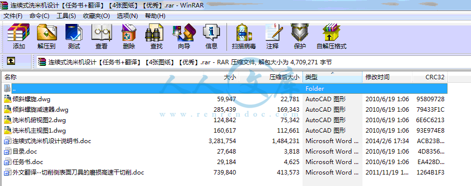
任务书.doc
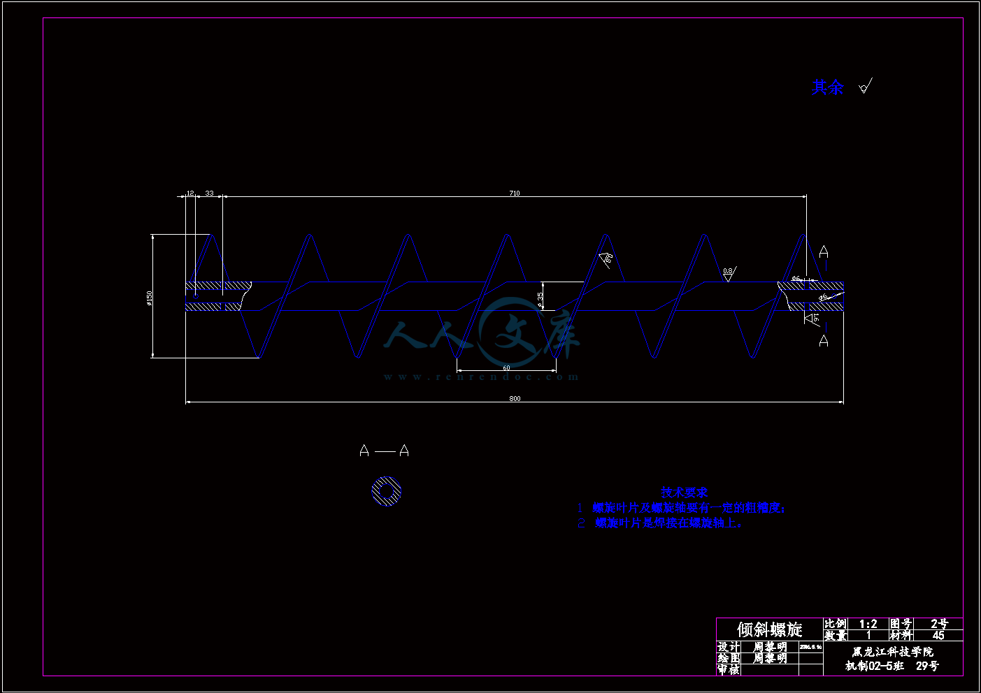
倾斜螺旋.dwg
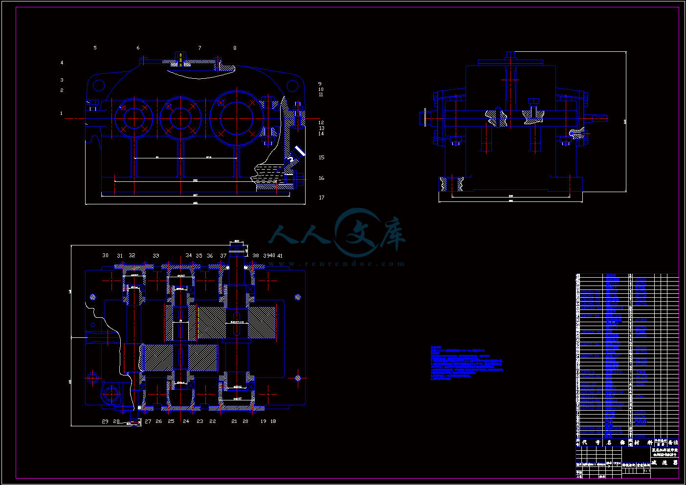
倾斜螺旋减速器.dwg
外文翻译--切削侧表面刀具的磨损高速干切削.doc
洗米机主视图1.dwg
洗米机俯视图2.dwg
目录.doc
连续式洗米机设计说明书.doc


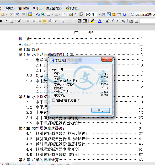
目 录
摘 要I
Abstract II
第1章 绪论 1
第2章 水平及倾斜螺旋设计计算 3
2.1 选取螺旋直径、转速及长度 3
2.1.1 水平螺旋设计计算 3
2.1.2 倾斜螺旋设计计算 4
2.2 功率计算及电机的选型 4
2.3 水平及倾斜螺旋校核计算 5
2.3.1 水平螺旋校核计算 5
2.3.2 倾斜螺旋校核计算 7
第3章 水平螺旋减速器设计 9
3.1 水平螺旋减速器高速级齿轮设计10
3.2 水平螺旋减速器低速级齿轮设计14
3.3 水平螺旋减速器高速级轴设计18
3.4 水平螺旋减速器中间轴设计25
3.5 水平螺旋减速器输出轴设计31
第4章 倾斜螺旋减速器设计37
4.1 倾斜螺旋减速器高速级齿轮设计37
4.2 倾斜螺旋减速器低速级齿轮设计41
4.3 倾斜螺旋减速器高速级轴设计45
4.4 倾斜螺旋减速器中间轴设计51
4.5 倾斜螺旋减速器输出轴设计57
第5章 机架的校核计算63
第6章 经济分析64
第7章 专题论文65
7.1 螺旋输送器的选用 65
7.1.1 应用范围及特点65
7.1.2 分类及结构特征65
7.1.3 布置形式66
7.2 设计计算 67
7.2.1 原始资料67
7.2.2 GX型螺旋输送器的计算 68
7.2.3 LS型螺旋输送器的计算 72
7.3提高螺旋叶片耐磨性的措施 74
总 结75
致 谢76
摘 要
本设计是根据国内外洗米机的发展趋势:小型化,高效率,结构简单等,而设计的一种能除去谷壳等漂浮杂质及沙石、用水量少的新型连续式洗米机。适用于学校食堂,大型饭店等部门,操作安全方便以及制造成本低等优点。着重设计计算了水平螺旋,倾斜螺旋及与其向对应的减速器的设计校核计算,机架的设计与校核;水平与倾斜螺旋上的叶面采用实体叶面即S制法,以便于输送粒状物料;减速器的设计中又着重设计与校核齿轮和轴,本设计的减速器是二级展开式减速器,二级展开式减速器能实现较大的传动比,应用较广,其中各级传动比的分配方案不同将影响减速器的重量及外观尺寸和润滑状况。减速器中采用了直齿齿轮传动,深沟球轴承,脂润滑。减速器与螺旋的联结采用联轴器联结。
关键词: 连续式 洗米机 原理 结构
Abstract
The design is based on the river and the development trends: small size, high efficiency and simple structure, designed to remove floating silver, and other impurities and sand, a new low-water river plane. Apply to school canteens, large hotels and other departments, operational safety and convenience advantages of low manufacturing costs. On the calculation of the level design spiral, tilted downward and its counterpart to the reducer design verification terms, the design and verification racks; Level and tilted spiral leaf surface of the leaf surface entities that use s-law to facilitate transmission granulose materials; Reducer also focus on design and design verification gear and axle, The design is secondary to the reducer - reducer, 2-reducer to achieve a larger than projected, broader applications, including the distribution of the different levels of transmission than reducer will affect the appearance and size and weight provide lubrication conditions. Reducer used straight teeth gear transmission, the passenger ball bearings, resin provide lubrication. Reducer used shaft coupling linking up with the screw.
Key words:continuous washing rice machine principle constitution
- 内容简介:
-
黑龙江科技学院毕业设计(论文)任务书姓名: 周 黎 明 任务下达日期: 2006 年 3 月 13 日设计(论文)开始日期: 2006 年 3 月 13 日设计(论文)完成日期: 2006 年 6 月 20 日一、设计(论文)题目: 连 续 式 洗 米 机 二、专题题目: 螺旋输送器的原理与设计 三、设计的目的和意义: 此项目的研究在于提高对大量米的洗涤效率,减少对水源的浪费,并可大大的降低食品加工人员的工作量以实现优质高效的洗涤效果。由于我国人口众多特别是在学校、工厂及餐饮行业都需解决对大量米的洗涤工作,通过对国内相关食品机械的调查可看出目前对洗米机的需求量呈增长趋势。 四、设计(论文)主要内容: 对于本次设计主要包括:1洗米机总体结构的设计;2洗米机动力系统的设计(电机的选择及减速器的设计);3洗米机工作装置的设计(螺旋输送器的设计)。最终设计结束后达到3张0号装配图和一张零件图以及2万于字的毕业设计说明书。 五、设计目标: 在洗米机的设计过程中主要需实现对米洗涤的连续性以达到对米的连续洗涤。机组设计的要求是:一、米在用螺旋输送后过程中同时进行揉搓,使机组结构简单,运作可靠;二、米流成逆流流动保证了用水少和较好的洗涤效果;三、漂浮杂质中足够的漂浮空间,保证洗涤能较彻底地除去米中的漂浮杂质。六、进度计划: 2006年3月13日至3月31日进行为期3周的生产实习;4月1日至4月10日完成对设计题目的资料收集与查询;4月11日至4月20日完成对洗米机总体结构的初步布置;4月21日至5月7日完成对各零部件的参数验算;5月8日至5月31日进行设计图纸的绘制;6月1日至6月10日进行毕业设计说明书的编写;6月11日至6月20日最后的审稿及说明书和图纸的打印。 七、参考文献资料: 包清彬主编.新型连续式洗米机.四川工业学院学报. 2001; 无锡轻工业大学,天津轻工业学院合编.食品工厂机械与设备.北京:中国轻工业出版社,1997;胡勇克主编.螺旋输送器的原理与设计.南昌大学机械工程学院. 2000; 编辑委员会编.运输机械设计选用手册.化学工业出版社下册 1992。 指 导 教 师: 院(系)主管领导: 年 月 日附录1 外文译文第四章 切削侧表面刀具的磨损高速干切削4.1前言许多不同类型的切削刀具都存在着不同程度的磨损,无论是在侧面、凹面或凸面。 侧面磨损技术源于平面技术在新兴边缘摩擦工作面的发展;主要原因是摩擦表面的数字显示见图4-1。它可以测量侧面磨损的宽度(VB). 对于凹面磨损来说由于存在磨粒磨损及其扩展于黏附。因此凹面磨损需测量凹陷的深度(KT)。凸面磨损与侧面磨损的原理基本相同。一般经常用到的是磨损宽度VB和凹陷深度KT(见图4-2)因为他们可以比较清楚的反映出加工工件的路径。然而,凸面则显得更难以测量。在机械工程发展的过程中侧面磨损被广泛的用于大量测量磨损的标准。图4-2显示了机械磨损的结果,这表明了侧面磨损技术标志着一个新的切削时代的到来。最初的高速磨损经常发生在切削过程的开始阶段。第二个区域也是比较好的一个区域它处于一个稳定或接近稳定的磨损率,其磨损率主要取决于切削速度和切削刃。第三个区域也是最后一个区域,在这个区域里磨损率将迅速增长他将导致切削刃毁灭性的破坏。对这一现象的解释是,侧面与工作面的摩擦而导致温度的升高,从而引起连锁反应使得温度迅速升高。4.1.1碳化铁自从碳化铁被用于刀具的原材料以来它就大量的作为刀具生产的原料。这种材料的制作是通过粉末冶金技术的微粒烧结和加如金属粘合挤而成的高硬度碳化物。与高速钢相比,这种碳化铁提供了较好的硬度和在较高温度下的热化学稳定性。作为金属粉末产品,这种碳化铁可以生产出不同档次的产品以应用于不同领域。这种技术可以加工各种不同几何形状的工件,当然也可以用特制的刀具夹头或较昂贵的黄铜手柄放在上面。这种化学胶结碳化物的组成通常包括碳化钨(WC),碳化钛(TiC)和碳化钽(TaC)且用钴作为粘合挤。对于上述化学物质每个公司都有自己的混合比例。就碳化铁的机械特性来说,如可延展性和韧性取决于其中所含碳化物的等级和密度。此外,碳化铁的硬度及抗压强度在1100C时如能达到800 MPa则TiC的含量将达到12%,如要使其硬度在800 C达到1.5GPa时则合金的比例分配将是TiC19%,TaC16%和Co9.5%。图4-1 刀具的磨损图4-2 切削过程中侧面的磨损状况4.2 涂层从70年代初涂层技术开始引进以来导致了硬质合金涂层生产的极大提高。此后这种涂层技术几乎应用于各种切割刀具。涂层就像一堵屏障以防止切削碎片和原料的工作表面发生相互作用。到目前为止已经开发出了各种不同类型的涂层材料,包括氮化钛(TiN),碳化钛(TiC),三氧化二铝(AL2O3 )和氮化锆(ZrN)。一般来说,其硬度高于200VDH并在铁的参合下溶解性极低。在机械设备中的钢和铁都存在锈蚀和脱落的问题,这些涂层能够使延长他们的使用寿命。但是涂层技术并不能应用于防止切削刀具的折断与破损。在刀具上应用涂层TiN,TiCN和A12O3显示了其具有阻碍和降低刀具表面的磨损的作用。以下是常用的涂层技术:4.2.1单层涂层这种技术是将TiC以化学蒸汽的形式沉积到硬质合金表面上而提出的。然而,在使用这个过程中的缺点是硬质合金上的涂层会带走金属表面的碳。这将打破化学平衡和刀具成分的变化从而使涂层和刀具本体的分界层变的比较脆,这将使刀具在切入工件时在刀具边缘出现容易断裂的结果。4.2.2多层涂层这种类型涂层技术的提及被称为“三明治”涂层,根据涂层材料的不同而有不同的组合最多可显示多达8层以上涂层。这种“三明治”涂层技术的最后一层厚度能达到10-15微米,它远远大于进行涂层过程中的第一层涂层。但是,第一涂层将是最佳结合性能单一涂层。多层涂层技术一般由TiN/TiCN/ AL2O3涂层,TiN/ AL2O3/ TiC / TiCN涂层或者它们之间的组合。另一方面,涂层中也引进了一些张力与压力的概念以提高刀具抗拒机械冲击的过程。在侧面磨损与凹面磨损之间有着不同类型的涂层。TiN涂层用于凹面的抗磨性比TiC涂层好而在侧面上用TiC涂层将比TiN涂层的抗磨性好。但是,在侧面或凹面上采用涂层AL2O3的抗磨效果几乎是相同的,就像在侧面上采用碳化物涂层及在凹面上采用氮化物涂层一样。最近报道显示,塑料在抗变形能力上将比其他材料要优越的多因而在抗磨性上有取代铝化物涂层的趋势。4.3干燥条件下机械磨损的研究关于刀具的使用寿命实验数据在第三章已加以论述,机械磨损的研究将在4.4节、4.5节和4.6节加以论述。通过这几节的论述将加深对涂层技术研究的理解提供有益的启示,优化机械操作和对涂层材料及涂层技术的改进提供必要的知识。因为磨削类型的分类是根据切削速度来进行的,所以对微小磨削非传统切削速度(即HSM)的研究将是非常必要的。通过这次实验将首次对磨削寿命及高速干切削条件下的微型机械磨削进行研究。对于非传统切削速度的重要性是他能缩短生产时间、增加盈利及减少机械故障。4.4碳化铁机械磨损的实验观察干燥条件下的机械切削在这一节中将对碳化铁刀具切入4140钢时的微型机械磨削进行实验和观察。根据图4-3A显示切削刀具在达到最大磨损极限时的切削速度通常是180m/min。它显示了滑移磨损出现在刀具工作表面的侧面位置,即滑移产生在工件表面和刀具切入的侧面。可以看出在侧面磨损中切入深度达到最大时的磨削深度。然而将侧面进行放大1500倍后,如图4-3B,则能看见微小的滑痕。在对钨化铁刀具进行实验时其结论也几乎是相同的。随着切削速度的增加,在切削速度达到180m/min时温度可增加到1115;从而导致硬度的急剧下降。图4-3B显示了机械磨损的微小滑痕,这在钴作为切入材料的粘合剂时得到了证实,碳的颗粒将在侧面上产生而粘在粘合剂上。因此,它的结论是在切削速度达到180m/min时,滑移和微小滑痕都将出现。图4-4A显示了在干燥条件下切入时切削速度达到150m/min的滑移磨损现象。切入侧面的边缘出现了典型的相互平行的滑移磨损沟槽。它类似于碳化钨的滑痕半径30微米。(A) 切削速度在180m/min时的滑移磨损显微图(B)切削速度在180m/min时的滑痕显微图图 4-3 切速180m/min时的放大图(A)切削速度在180m/min时的滑移磨损显微图(B)切削速度在180m/min时的滑痕显微图其它类型的机械微小磨损的研究也和上述类型相似,如图4-4B所示,一条微小的滑痕在狭窄的沟槽中显示。据报道同样类型的磨损现象在陶瓷刀具中也出现过。由于将钴作为切削刀具的粘合剂则微型沟槽在切削侧表面大量的出现。因此,它的结论是在150m/min的切削速度下滑移磨损和微型机械滑痕都将大量出现。由于在金属切削过程中存在多种机械磨损;包括氧化、扩散磨损、腐蚀磨损和疲劳磨损。因磨损的存在则刀具的切削刃是焊接在刀柄上的。因为刀刃与刀柄之间是焊接为一体的则焊接处刀柄有一缺口以便于安放刀刃。机械磨损的效力在于刀具表面出现磨粒的硬度。因此刀具切削刃的切削能力与摩擦颗粒的硬度有关。磨损的扩散方向是由刀刃与金属碎片之间的原子引力来决定的;它将导致原子移动的两个不同方向。这种方法是通过提高温度、压力和接触时间来实现的。机械疲劳是由于刀刃的连续压缩与张力而形成的且刀刃所承受的压力高于刀刃的机械强度。另一方面,连续的降温和升温也有可能导致热疲劳。(A) 切削速度在150m/min时的滑移磨损显微图(B)切削速度在150m/min时的滑痕显微图图 4-4 切速150m/min时的放大图(A)切削速度在150m/min时的滑移磨损显微图(B)切削速度在150m/min时的滑痕显微图当切削速度在120m/min时刀具侧表面与工件的接触方向一般会出现纵向平行的沟槽。如图4-5所示在刀具侧表面磨损率较底或较高的区域都将会出现沿金属碎片脱落方向而存在的暗淡脊状条痕。这表明机械磨损的微小黏附是存在的。在刀具AISI 4340的刀刃中加入铝的化合物(Al2 03 + TiC )时也存在着类似的结果。随着切削速度下降,刀刃和切削区域的温度也随之下降。另外随工件材料脱落的切削碎片的黏性也比高速切削时底,但也足够于黏附在刀具切入时的刀具侧表面。同时如另一张放大倍数更高的图4-6A所示可明显的看见刀具侧表面摩擦黏附所凸起的脊状物。这种脊状条痕也比其它相进的刀具材料所形成的脊状条痕大。随着刀具侧表面与工件本体之间的连续摩擦这种粘附在表面的金属层也会被摩擦掉。因此,一种新的机械磨损出现了即微小摩擦磨损。一些低质材料也将随着粘附金属层的移动而带走。如图4-6B所示微小摩擦的特征是在表面上出现了微小的孔穴。当切削速度达到90m/min和60m/min时则在刀具凹面将出现刃状。如图4-7A所示在刀刃上出现了新的刀刃。因为在干燥的环境下进行切削,所以一种无油润滑且洁净的高速干切削是可以利用的。这些都是理想情况下在切削凹面上形成的压力熔接点称为BUE。它是在切削表面的碎片流动速率不是很高的情况下形成的。这显示了碎片流过凹面部分的流速将随碎片上层至底层逐级递减且最底层黏附在刀具凹面不动。这儿有两种类型的BUE。一种是显示在速率90和60m/min时切削材料为4140时是稳定的。这个迹象阐明了刀具在这两个切削速度的寿命最长。此外,如图3-5所示在稳定的区域加大切入长度并在高速切削时在刀刃上将不存在压力熔接点。尽管如此,压力熔接速率也和切入表面的粘性碎片移动速率相等。这就是压力熔接技术(BUE)在切速90和60m/min时稳定和连续的原因。图4-7B是压力熔接层放大1000倍的示意图,它显示了多层碎片溶解层的重叠。图4-5 切速120m/min时的脊状条痕和滑移磨损显微图(A)切速120m/min时的微小黏附磨损显微图(B)切速120m/min时黏附层脱落后的微小摩擦磨损显微图图4-6 切速120m/min时的侧面区域显微图(A)切速120m/min时的微小黏附磨损显微图(B)切速120m/min时黏附层脱落后的微小摩擦磨损显微图(A) 切速90m/min时刃状的出现(B)切速90m/min时似刃状的多层碎片溶解层图 4-7 切速90m/min时的放大图(A)切速90m/min时刃状的出现(B)切速90m/min时似刃状的多层碎片溶解层附录2 外文原文CHAPTER IVTOOL WEAR MECHANISMS ON THE FLANK SURFACE OF CUTTING INSERTSFOR HIGH-SPEED DRY MACHINING4.1 IntroductionOn the cutting tool many different types of wear mechanisms could take place, on either the flank surface, crater surface, or cutting tool nose 1. Flank wear takes place by forming a flat surface that develops where the edge rub the newly generated work piece surface; primarily because of the abrasive wear as shown in Figure 4-1. It can be measured by the width of the flank wear land (VB). Crater wear, on the other hand, can be developed due to abrasive wear, diffusion and adhesion wear. Crater wear is measured by crater depth (KT). Nose wear is taken place by the same mechanism of wear on the flank surface, which is abrasion wear 54. KT and VB (see Figure 4-2) are frequently used because they can be measured in a fairly objective way. However, nose is more difficult to quantify. The flank wear is most widely reported as a criterion to measure the amount of wear, that takes place in the machining process 54.Figure 4-2 shows the effect of the wear mechanism, in this case the flank wear on the new cutting edge against time. A rapid initial wear usually is caused by the break-in that begins the process. The second region on the right is the steady state or nearly steady rate of wear, which depends mainly on the cutting speed or (chip removal) over the cutting edge. The third and last region is the rapidly increasing wear rate the proceeds to a catastrophic failure of the cutting tool edge. The explanation for this phenomenon is that the heat generated by rubbing the flank surface on the work piece causes a rise in temperature, which leads to a chain reaction of rubbing and raising temperature.4.1.1 Uncoated Cemented CarbideCemented carbide since its discovery as a cutting tool material has been the most frequently used cutting tool material for high production 1. This material is fabricated with powder metallurgy technology by sintering fine particles of hard carbide in a metal binder. In comparison with high-speed steel, cemented carbide provides a superior hardness chemical stability at elevated temperature. Figure 4-1 Tool wear measurement.Figure 4-2 Wear situations on the flank surface of the cutting tool.As a metal powder product, the cemented carbide can be produced with different grades for different applications 2. Cutting inserts with various geometries can be produced by this technique that either need a special tool holder, or one that can be brazed onto a less expensive shank. The chemical composition of the cemented carbide, usually includes tungsten carbide (WC), titanium carbide (TiC), and tantalum carbide (TaC) with cobalt as a binder. Each company has its own blending ratio for the aforementioned chemicals. The mechanical properties such as toughness and ductility may be low and both depend on the density and the grade of the carbide. Furthermore, the hardness and compressive strength are high that go up to 800MPa at 1100 C for cemented carbide that has 12% TiC and the compressive stress of an alloy that has 19% TiC,16% TaC and 9.5% Co reaching 1.5GPa at 800 C 2.4.2 CoatingsSince their introduction in early 70s, hard metal coatings have resulted in tremendous increase in production. Since then they have been applied on almost all types of cutting tools. Coatings, however, work as a diffusion barrier to prevent interaction between the chip formed and the work piece material. Different types of coating material have been developed in the past, including titanium nitride (TiN), titanium carbide (TiC), Alumina (AL2O3), and Zirconium nitride (ZrN). In general, their hardness is higher than 200VDH and has very low solubility in iron. In machining cast iron and steel, these coatings have proven their success in extending the tool life by a factor of 2 to 3 2. However, coatings cannot be applied where severe interruptions of cut may cause fracture and damage to the coatings.Dearnly and Trent 17 have indicated that the wear resistance of TiN, TiCN, and A12O3 are because of their high diffusion resistance on the parts of the tool surface where seizure occurs. The following techniques are commonly used in coating:4.2.1 Single layer coatingsThis technique was first presented by placing a single layer of TiC using a chemical vapor deposition onto a substrate of hard metal 1. However, the disadvantage of using this process in coating hard metal is that some carbon is taken away from the surface of the metal. This changes the chemical balance and results in a brittle compound at the interface between the coating and the substrate, which makes the insert susceptible to fracture at the tool edge.4.2.2 Multiple layer coatingsThis type of coatings is referred to as sandwiched coatings, in which different combinations of different coating materials are used to display up to eight layers over the substrate. The final thickness from multiple layering processes sandwiched can reach 10-15 m, which is much greater than that of the process trying to produce it by one step. However, this process combines the best properties of single coatings.Multiple coatings are made up of TiN/TiCN/AL2O3 layers, TiN/AL2O3 l TiC / TiCN or their repetition. On the other hand, the layers also introduce some pre-tensioning in the form of compressive stresses to help the tool withstand the impact of the machining process.In regard to flank wear and crater wear there are differences between the different types of coating. TiN is resistant to crater wear than TiC and TiC is more resistant to flank wear than TiN. However, the substrate coated with Alumna AL2O3 has almost the same resistance to flank and crater wear as the inserts coated with carbide and nitride. Dearnly 17 has reported that plastic deformation is the dominant type of wear that takes place on the Alumina coated inserts rather than diffusion wears.4.3 Wear Mechanism Study Under Dry ConditionIn an attempt to explain the experimental tool life data presented in (Chapter3), wear mechanisms study was carried out through out Section 4.4, Section 4.5, and Section 4.6. It will provide a useful insight for understanding the tribological behavior of coating under study, optimizing machining operations, and to provide essential knowledge to the improvement of coating materials and coatings techniques. Since the wear type is dependent on the cutting speed 2, 18, 19, 22, 26, it is important to investigate the micro-wear that might be activated at unconventional cutting speeds (i.e. HSM). Through this attempt, it will be the first time to investigate the wear life, and micro-wear mechanisms of these cutting inserts under Dry High Speed Machining range and in cutting SAE 4140 (DHSM). The importance of (HSM) comes from shortening production time, increasing profitability, and decreasing machine downtime.4.4 Experimental Observations of Wear Mechanisms of Uncoated Cemented CarbideCutting Inserts in Dry MachiningIn this section, the experimental findings and observations of micro-wear mechanism with uncoated cemented carbide tool inserts in machining 4140 steel are presented. In light of Figure 4-3A the cutting inserts were used at a cutting speed of 180 m/min after the cutting tool reached the maximum wear limit. It is observed that a sliding wear occurred at the flank surface position at the tool work interface, where sliding occurs between the newly generated work piece material and the flank side of the cutting insert. It can be seen that the configuration of the wear pattern on the flank side reaches its maximum depth at the maximum depth of cut and reduces toward the cutting nose. However, taking a close look at the flank surface with a magnification of 1500 times as shown in Figure 4-3B, it can be seen that a micro abrasion wear was formed. Jie Gu et at 36 also reported similar results regarding the behavior of uncoated tungsten carbide milling inserts. As the cutting speed increases, the temperature may increase up to 1115 C at 180m/min 2; as a result the hardness decreases.Micro-abrasion wear mechanism is revealed from Figure 4-3B, this is justified by the fact that the cobalt is used in the cutting inserts material as a binder 18. It is worn faster and then the carbide grains protrude out of the flank face. Hence, it is concluded that at this cutting speed (180m/min), both sliding and micro-abrasion wears are activated.Figure 4-4A was taken for cutting inserts machined at a cutting speed of 150 m/min under dry conditions. A typical sliding wear at the flank edge of the cutting insert is revealed indicating grooves parallel to the contact direction. It is similar to Kojis 32 findings on Tungsten Carbide inserts in sliding test against diamond pin 30 radius.(a) SEM micrographs of (KC313) at 180m/min showing sliding wear(b) SEM micrographs of (KC313) at 180m/min showing micro-abrasion wear.Figure 4-3 Magnified images of (KC313) at 180m/min: (a) SEM micrographs of (KC313) at 180m/min showing sliding wear, (b) SEM micrographs of (KC313) at 180m/min showing micro-abrasion wear.To investigate closely other types of micro-wear mechanisms, a zoom-in view was taken at the surface as shown in Figure 4-4B, a micro-abrasion appeared in the narrow grooves. Chuanzhen 45 reported the same type of wear when machining Inconel with Ceramic tools. The micro-grooves developed on the flank surface are due mainly to the cobalt used as a binder in this cutting inserts material. Therefore, it is concluded that at 150 m/min cutting speed sliding wear and micro-abrasion wear mechanisms will be developed.Several wear mechanisms occur during metal cutting; these include oxidation, diffusion wear, abrasive wear, and fatigue wear 26. Attrition wear leading to a build up edge (BUE), is a localized welding of material during sliding. Since the material is moving, the welding points get broken and take small parts away from the cutting tool. Abrasive wear is a mechanism of wear where a grinding effect takes place between hard particle and the cutting tool surface under load. The ability of the cutting edge to resist the abrasive wear is related to its hardness Jie Gu et al 18. Diffusion is due to difference in atomic concentration between the cutting tool edge and the metal chip; that leads to atomic transfer in two directions. This technique is enhanced by temperature, pressure, and contact time. Fatigue is caused by successive compression and tension on the cutting edge that leads to mechanical fatigue if the applied pressure is higher than the mechanical strength of the cutting edge. On the other hand, a successive cooling and heating may lead to a thermal fatigue.The flank surface at 120m/min also has micro-abrasion wear indicated by the longitudinal grooves laid parallel to the contact direction. The flank side has an appearance of dull flat as shown in Figure 4-5 containing ridges lying in the direction of metal chip flow and regions of lower wear rate and others with higher wear rate. This indicates the presence of micro-adhesion wear mechanism. Avila et al 20 recorded similar results when machining AISI 4340 with mixed alumina tools (Al2 03 + TiC). As the cutting speed drops, the temperature drops at the shear zone and cutting tool edge as a result. h1 addition, the ductility of the flowing chips from work piece material decreased to a point much less than at higher cutting speeds, but enough to be susceptible to adhere to the flank side of the cutting insert. Taking another image at a higher magnification as in Figure 4-6A it can be noticed that the micro-adhesion wear takes place at the flank surface forming ridges at the side of the cutting tool. The ridges were formed resulting high levels than the adjacent material to be worn along the sides of these ridges. The adhered metal layer was plucked away from the flank surface because of continuous rubbing (a) SEM micrographs of (KC313) at 150m/min showing sliding wear.(b)SEM micrographs of (KC313) at 150m/min showing micro- abrasion .Figure 4-4 Two images of (KC313) at 150m/min:(a) SEM micrographs of (KC313) at 150m/min showing sliding wear, (b) SEM micrographs of (KC313) at 150m/min showing micro- abrasion.between the flank side and the newly generated metal surface. Therefore, a new wear mechanism was activated, which is the micro-attrition wear. Some of the substrate material was plucked away with the removal of adhered metal. As result micro-holes appeared showing the characteristic feature of micro-attrition as shown in Figure 4-6B. This is again is supported by similar results observed by Gu at al 36.Built up edge (BUE) was noticed on the cutting tool crater surface when machined at a cutting speed of 90 m/min and 60 m/min. Its similar to the findings reported by J. Gu 18 in machining resulphurized 0.08 wt-%C steel and C. Lim 31 in testing C5 milling inserts. Figure 4-7A, however, shows a build up edge sticking on the cutting tool edge. Since the machining was carried out at dry conditions, a clean surface was available since no oil lubricant was used along with the resultant high heat during cutting. These were ideal conditions to form pressure welding on the cutting crater surface, called BUE. It takes place when
- 温馨提示:
1: 本站所有资源如无特殊说明,都需要本地电脑安装OFFICE2007和PDF阅读器。图纸软件为CAD,CAXA,PROE,UG,SolidWorks等.压缩文件请下载最新的WinRAR软件解压。
2: 本站的文档不包含任何第三方提供的附件图纸等,如果需要附件,请联系上传者。文件的所有权益归上传用户所有。
3.本站RAR压缩包中若带图纸,网页内容里面会有图纸预览,若没有图纸预览就没有图纸。
4. 未经权益所有人同意不得将文件中的内容挪作商业或盈利用途。
5. 人人文库网仅提供信息存储空间,仅对用户上传内容的表现方式做保护处理,对用户上传分享的文档内容本身不做任何修改或编辑,并不能对任何下载内容负责。
6. 下载文件中如有侵权或不适当内容,请与我们联系,我们立即纠正。
7. 本站不保证下载资源的准确性、安全性和完整性, 同时也不承担用户因使用这些下载资源对自己和他人造成任何形式的伤害或损失。

人人文库网所有资源均是用户自行上传分享,仅供网友学习交流,未经上传用户书面授权,请勿作他用。
 川公网安备: 51019002004831号