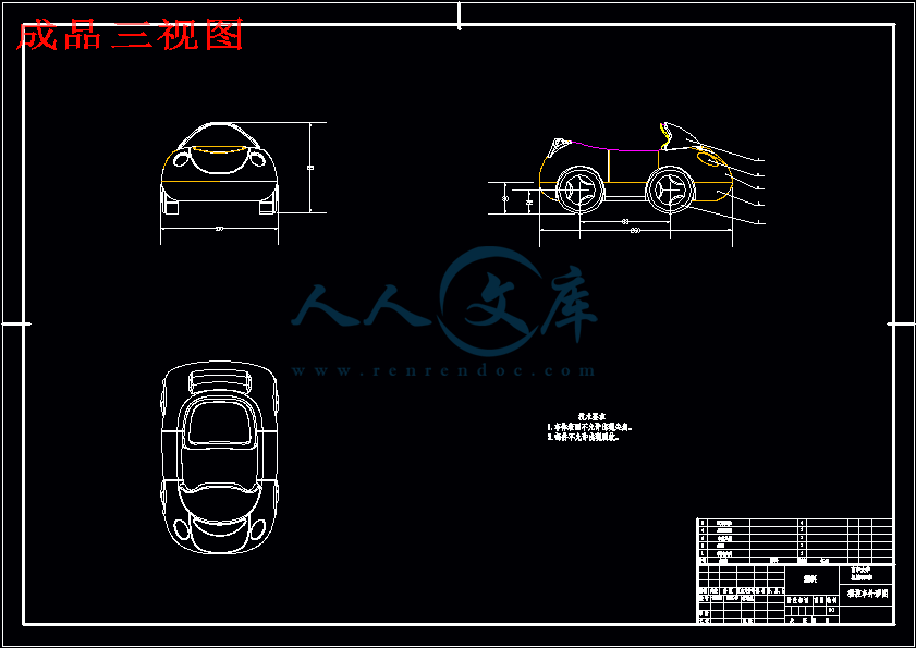
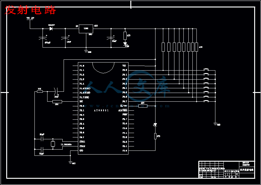
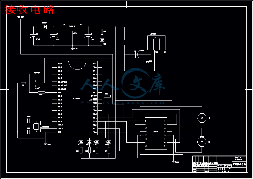
程序流程图.dwg
程序流程图.dwg

智能化自寻迹程控车模外形及其控制系统设计【4张CAD图纸+毕业论文】

收藏

压缩包内文档预览:
预览图
编号:424097    类型:共享资源    大小:530.34KB    格式:RAR    上传时间:2015-04-10 上传人:上*** IP属地:江苏
39
积分
关 键 词:
智能化 自寻迹程 程控车模 外形 及其 控制系统 设计 cad图纸 毕业论文 智能化自寻迹程控车模 智能化自寻车
资源描述:

智能化自寻迹程控车模外形及其控制系统设计

58页 19000字数+说明书+任务书+开题报告+外文翻译+4张CAD图纸【详情如下】

任务书.doc

发射电路.dwg

外文翻译--柔性制造系统.doc

成品三视图.dwg

接收电路.dwg

摘要.doc

智能化自寻迹程控车模外形及其控制系统设计开题报告.doc

智能化自寻迹程控车模外形及其控制系统设计论文.doc

目录.doc

程序流程图.dwg
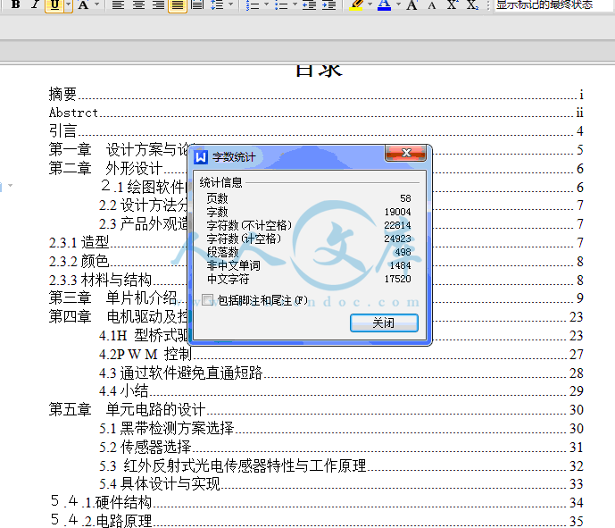
目录

摘要i

Abstrctii

引言4

第一章 设计方案与论证5

第二章  外形设计6

2.1绘图软件的选择6

2.2设计方法分析7

2.3产品外观造型的三大美学因素7

2.3.1造型7

2.3.2颜色8

2.3.3材料与结构8

第三章  单片机介绍9

第四章  电机驱动及控制23

4.1H 型桥式驱动电路23

4.2P W M 控制27

4.3通过软件避免直通短路28

4.4小结29

第五章  单元电路的设计30

5.1黑带检测方案选择30

5.2传感器选择31

5.3 红外反射式光电传感器特性与工作原理32

5.4具体设计与实现33

5.4.1.硬件结构34

5.4.2.电路原理35

5.4.3程序及流程图38

6.1总结43

参考文献46

致谢47

摘要

本文介绍了利用红外反射式传感器实现小车自动寻迹导航的设计与实现。自动寻迹是基于自动导引小车(AGV—auto-guided vehicle)机器人系统,用以实现小车自动识别路线,判断并自动规避障碍,以及选择正确的路线。实验中采用与地面颜色有较大差别的线条作引导,使用反射式红外传感器感知导引线和判断障碍物。系统控制核心采用AT89S51单片机,系统驱动采用控制方式为单向PWM的直流电机。该技术可以应用于无人驾驶机动车,无人工厂、仓库、服务机器人等领域

关键词:自动寻迹;红外传感器 ;单片机

Abstrct

This article   introduces the design and execution of auto-searching for track by usage of the reflected infrared sensor on the auto-guided car. The auto-searching for track is on the base of the AGV-auto-guided vehicle system. It makes the car discern the routs, judge and evade the obstacles automatically. So the car can choose the right routes. In the experiment we take use of the guiding wire whose color distinguishes from the background to guide the car and the inflected infrared sensor to discern the guiding wire and obstacles. The AT89S51 Single Chip Microcomputer is used for the control core in this system, and the one-way PWM direct current electromotor for the motive force or power system. This technology could serve to driverless mobile, robot factory, warehouse, service robot and etc.

Key Word:Auto-searching for track; infrared sensor; Single Chip Microcomputer

引言

自第一台工业机器人诞生以来,机器人的发展已经遍及机械、电子、冶金、交通、宇航、国防等领域。近年来机器人的智能水平不断提高,并且迅速地改变着人们的生活方式。人们在不断探讨、改造、认识自然的过程中,制造能替代人劳动的机器一直是人类的梦想。

随着科学技术的发展,机器人的感觉传感器种类越来越多,其中视觉传感器成为自动行走和驾驶的重要部件。视觉的典型应用领域为自主式智能导航系统,对于视觉的各种技术而言图像处理技术已相当发达,而基于图像的理解技术还很落后,机器视觉需要通过大量的运算也只能识别一些结构化环境简单的目标。视觉传感器的核心器件是摄像管或CCD,目前的CCD已能做到自动聚焦。但CCD传感器的价格、体积和使用方式上并不占优势,因此在不要求清晰图像只需要粗略感觉的系统中考虑使用接近觉传感器是一种实用有效的方法。

机器人要实现自动导引功能和避障功能就必须要感知导引线和障碍物,感知导引线相当给机器人一个视觉功能。自动寻迹是基于自动导引小车(AGV—auto-guided vehicle)系统,实现小车自动识别路线,判断并自动规避障碍,选择正确的行进路线。采用与地面颜色有较大差别的线条作引导,使用传感器感知导引线和障碍判断

第六章  操作说明

整个制作过程全部手工焊接而成,车身长约20cm,宽约15cm,高约10cm。由于设置为纠偏检测,因此具有闭环系统特征,从制作效果上看,能够较好地反映闭环控制原理。

操作时,先做好轨迹(可用白纸在黑胶皮上制作),然后将车模放于其附近。打开电源时,电路开始检测p3口状态,当确认为低电平(即已按下SB2)时,车模演奏一曲欢乐颂,然后返回初始状态。反之,则发出“嘀嘀”声间歇前进,并在检测到轨迹后“跟踪”轨迹行走。当轨迹为直线时,车模恢复间歇运动状态,以控制自身速度,直到下一次偏差产生。

当计数器溢出时,检测停止,车模后退一段距离,准备进行新一轮循环,如此反复。

程序在运行时“死机”现象很少,该车设有复位键SB1,可将系统复位后重新运行。

当车模垂直检测到轨迹时,讯响器动作,表示产生错误。也可将此功能作为其他报警装置开发。

自寻迹程控车及其各部分结构见附图。

参考文献

[1] 王晓君 ,安国臣等.MCS-51及兼容单片机原理与选型.电子工业出版社

[2] 薛栋梁. MCS-51/151/251 单片机原理与应用(第二版). 中国水利水电出版社

[3] 孙育才,王荣兴,孙华芳. ATMEL新型AT89S52系列单片机及其应用 .清华大学出版社

[4] 林清安.Pro/ENGINEER Wildfire 零件设计-进阶篇(上)中国铁道出版社

[5] 王和明 . 刘嵘 . AT89系列单片机及其编程  电子技术96年09期

[6] 崔晓燕. AT89系列高性能单片机及其应用   微型机与应用96年03期

   [7] 谈文心等. 模拟集成电路原理及应用.  西安交通大学出版社.   1995.

[8] 沙占友. 集成化智能传感器原理与应用. 北京:电子工业出版社.2004.

[9] 何立艮.单片机应用系统设计. 北京航空航天大学出版社. 1990.

[10] 付家才. 单片机控制工程实践技术.   化学工业出版社.     2004.

[11] 张毅刚.  MCS251单片机应用设计. 哈尔滨工业大学出版社.   1997.

[12] 万富君,潘松峰.单片微机原理系统设计与应用.中国科学技术大学出版社

[13] 武庆生,仇梅.MCS 系列单片机及接口实用教程.电子科技大学出版社,1997.

[14] 王家桢, 王俊杰. 传感器与变送器. 清华大学出版社, 2001

[15] 涂时亮, 张友德, 陈张龙.单片机软件设计技术 科学技术文献出版社 1988.

内容简介:
南 华 大 学毕业设计(论文)任务书学 院: 机 械 工 程 学 院 题 目: 智能化自寻迹程控车模外形及其控制系统设计 起止时间: 2006 年 12 月 25 日至 2007 年 6月 5 日学 生 姓 名: 胡 金 兴 专 业 班 级: 机械设计制造及其自动化032班 指 导 老 师: 教研室主任: 院 长: 2006 年 12月 25 日设计(论文)内容及要求:一、 设计(论文)内容题目:智能化自寻迹程控车模外形及其控制系统设计 研究内容: 1)车体设计 2)控制系统设计1 红外遥控装置能控制单片机,使之发出进、退、左转、右转控制(并给出动作指示)。2 使用红外对管设计寻迹电路(即自动区别黑白道标记)。3根据寻迹信号设计单片机对电机的控制电路。4单片机采用汇编及C51进行编制,程序的下载为ISP方式。二、 要求:本课题主要培养学生的程序设计和绘图等实际能力,通过毕业设计,学生应初步具备工程设计的实际能力。1、程控小车的总体设计方案,设计小车外形轮廓,利用计算机绘制A0图纸一张。2、编写控制小车自动寻迹的原程序一份,3、整理,编写设计说明书,内容包括程控小车的外形设计和程序设计,不少于20000字,英文摘要500字左右,计算机打印。4、翻译有关英文资料1-2篇,不少于3000字,计算机打印. 指导教师: 年 月 日外文翻译英文原文:Flexible Manufacturing SystemA logical step from the concepts of group layout and of NC machine tools and robotics are computer-controlled interlinked outstation machining complexes, or 11exibe manufacturing systems(FMS)as they have bedclothes call.do.Such systems can be looked upon as highly automated cells manufacturing families of components.The concept of FMS is not a new one; the first proposals were made in the mid 1960s. In recent years we have seen a growth in the number of systems, particularly in Japan, such that it is estimated that in excess of a hundred systems have been installed worldwide. A flexible manufacturing system contains a number of features as follows:1. Interlinked NC workstations operating on a limited range or family of work pieces. In early propos-ales the machines were of modular construction, but in recent systems general-purpose NC machines, in particular machining centers, are most commonly used.2. Automatic transportation, loading at unloading of work pieces and tools, using automatic guided vehicles (AGVs), robots, etc.3. Work pieces mounted on pallets ft* transportation, pattly to overcome the problems of new setups at each workstation.4. Centralized NC or DNC, together with overall computer control of the system.5. Operation for significant periods of time with little or no manual intervention.With FMS the tern flexibility means the ability to aptness a variety of components without having to adjust machine setups. Or change tooling. High flexibility implies that a large family of different components can be produced by the particular system. Figure 5. 17 show that several variants of the basic FMS con-kept exist. These are;l.Flexible manufacturing cells(FMs): These are basically machining centum but with the addition of a pallet pool or magazine(Fig.5. t8 ).The aim is to machine the work piece with one stupefies type of machine can be operated unmanned for long periods of time, with the palletized work pieces transformed au-somatically to and from the machine. Flexible manufacturing cells of this type must be served by machines or operators engaged in blank preparation and polarization of work pieces. These cells are highly flexible in operation, having the ability to deal with a wide range of pats (40 to 800), in small batches of from 15 to 500.2. Flexible transfer lines (fall): These, systems consist of a number of NC or head-changeable ma chine tools connected by automatic material transfer systems. The system can machine different components but without flexible routing of the workpieces.The family of components is relatively small ( 20) and the components must be quite similar to one another, as the overall flexibility of tote system is too low for a larger variety to be accommodated. In consequence, the work cycles at each station nulls are quite well balanced. Production quantities must be quite large for economic use of these system (1 500 to 15000 per annum for each component).3. Flexible manufacturing systems (FMS), in these systems NC workstations are linked by automatic work piece transfer and handing. With flexible routing and automatic work piece loading and unloading. A-chining times at each station can differ considerably. The number of different components that can be pro-cussed by these systems is ohm 10 o 150 in general and moderate quantities can be produced (15 to 500 components per annum for type)1Work Handling for FMSWork pieces are usually mounted on standard pallets for processing in FMS and these pallets locate automatically at each workstation in the system. A variety of work-handling devices are used to transport parts, pallets, and tools around the system. Some of these ate as follows:1. Tow carts: These are the most cannon devices used; they consist of a simple platform on castors and are towed around the system by engagement with under floor, continuously moving chains. Cats stop at workstations by means of a mechanism total releases the tow pin at the appropriate time. Branches and loops are canalled in a similar manner to railway systems. 11te main advantage of tow carts is their simplicity and low cost, since no on-board power is required for their movement or control. Facilities must be available at each workstation to load and unload pallets from the carts. Also, the circulation of carts must be unidirectional.2. Automatic guided vehicles (AGVs). These devices are usually designed to follow wins buried in the floor of the plant or lines painted on tote floor. On-board power and control is required for bolt move mint and steering ate for tote handling of pallets. Automatic guided vehicles ate more expensive than tow cats and are both larger and heavier. Tale main advantage of AGVs is their greater flexibility of opera-ton. These devices may move in either direction, but for ease of control, circulation is usually restricted to one direction only in practice.3. Rail cats: These carts move on rails and are generally restricted to backward and forward motion along straight tracks. Power and control instructions ate ttunsferred by overhead conductors or extra rails. Rail carts often accommodate two pallets to allow for pallet exchange at the system workstations.4. Roller conveyors: Most of tote early FMS developments utilized powered-roller conveyors for moving work pieces from statuette to station. The use of these convents in modern systems is less common. Roller conveyors are expensive to install and occupy valuable floor space. In addition, these conveyors are relatively inflexible in operation and difficult to alter if the overall system is expanded.5. Industrial robots: Robots are used in FMS but not extensively unless the cell consists of only a few machines. They may be used as second at) handling devices, particularly for turned work pieces, which may be transported around the system in hatches on pallets by other handling devices and then transferred to the machine tool by robots at each workstation. Gripper designs suitable for handling a wide variety of components are important in this case.2 Layouts for FMSA variety of different layouts for the machine tools in FMS have been adopted, The choice depends on the scope of the system and the type of handling devices used for transporting work pieces from workstation to workstation. The use of rail carts mean that a straight track must be used, with machines located at the side of tote track. Early systems using roller conveyors usually employed a simple loop configura-tio11, with branches to the workstations.The increased use of tow carts and AGVs has resulted in more complex multicolor or tree-type layouts being used. The latter type is most suitable for AGVs and is particularly useful if expansion of the system with additional workstations is anticipated. Figure 5.19 shows a typical multicolor layout using tow carts, and Fig.5.20 shows a typical layout where AGVs are used for work handling.3 Factory of the FutureOn the basis of the advances made to date in all aspects of manufacturing technology and computer controls, we may envisage the factory of the future as a fully automated facility in which human beings would not be directly involved with production on the shop i1oor (hence the term unmanned factories).All manufacturing, material handling, assembly, and inspection would be done by automated and computer-controlled machinery and equipment.Similarly, activities such as processing incoming orders, production planning and scheduling, cost accounting, and various decision-making processes (usually performed by management) would also be done automatically by computers. The role of human beings would be confined to activities such as supervising, maintaining (especially preventive maintenance), and upgrading machines and equipment; ship-ping and receiving supplies and finished products ; providing security for the plant facilities ; and programming, upgrading, and monitoring computer programs, and monitoring, maintaining, and upgrading hard-ware.Industries such as some food, petroleum, and chemical already operate automatically with little human intervention. These are continuous processes and, unlike piece part manufacturing, are easier to automate fully. Even so, the direct involvement of fewer people in manufacturing products is already apparent: Surveys show that; only 10-15 percent of the workforce is directly involved in production. Most of the workforce is involved in gathering and processing information.Virtually unmanned manufacturing cells already make products such as engine blocks, axles, and housings for clutches and air compressors .For large-scale, flexible manufacturing systems, however, highly trained and skilled personnel will always be needed to plan, maintain, and oversee operation. The reliability of machines, control systems, and power supply is crucial to full factory automation. A local or general breakdown in machinery, computers, power, or communications networks will, without rapid human intervention cripple production. The computer-integrated factory of the future should be capable of automatically rerouting materials and production flows to other computers in case of such emergencies.译文:柔性制造系统以成组布局的方式,将由计算机控制的多台数控机床及机器人结合成多工位成套加工设备,即称为柔性制造系统(FMS),这种系统被视为对各类零件族进行加工的高度自动化制造单元。FMS并非是新的顿念,首先是在二十世纪60年代中期提出的。近年来FMS的数量不断增加,尤其是日本。据估计,世界上建立起来的FMS已经超过了一百套。柔性制造系统具有以下一些特征: l。将对范围有效的零件或某族零件进行加工的多台效控工作站互相联结。早期规划时FMS中的机床都采用单元结构、而近年来生产的FMS基本上采用通用数控机床,尤其是加工中心。 2通过自动运输小车(AGVs)机械手等设备时工件及刀具进行自动运送和装卸。3为便于传输,将工件装在托盘上,部分解决了工件装到每个工作站上去需进行重新调整的问题。4数控系统或直接数控系统与系统的计算机总体控制一起实行集中管理。5主要的加工过程无须人工干预或较少人工干预。柔性制造系统这一术语中的柔性意味着该系统在不必调整机床设备或更换工艺装备的情况下就能加工各类零件。柔性大是指莱某一特定的系统能加工某一大零件族的不同零件。图5。I 7示表示了现有的基本的FMS概念引出的一些派生系统,即:1柔性制造单元(FMS):它基本上是带有托盘库或托盘站的加工中心(图5,1 8)。其目的是在一次安装下便可加工出工件。这种柔性制造单元可长时间无人看管。装在托盘中的工件可自动送达以及运离该加工机床。这种类型的柔性制造单元必须由机械装置或操作人员进行毛坯准备前将工件装在托盘上。柔性制造单元的加工柔性高,可小批量(15到5 00)地加工多种零件(40 8 00种)。2柔性自动线LTLs)。这些系统是由多台数控机床或可更换主轴箱的机床所组成,机床之间通过物料自动输送系统相联接。此系统可加工不同的零件,但工件的加工路线不能变动。可加工的零件族种类比较少(20)而且它们之间必须十分相似,这是因为这类系统的柔性太小,所加工的工件不可变化太太。所以每个工作站上的加工时间必须相等。要使这些系统加工经济则产量必颂大(每种零件的年产量应为1500到15000件)。3柔性制造系统(FMS)。此类系统的数控工作站由工件的自动榜送和搬运系统相联接,能够改变加工路线,并可自动装卸工件。每个工作站的加工时间可能相差较大。柔性制造系统可加工的零件种类一放为10 150种,适于中等批量的生产每一类零件的年产量为15 到 500件。图5。17 各种FMS的概念柔性自动化。 柔性自动线:机床内部联系;多用途加工;周期地输送工件;控制物料流动;加工设备的部分运用性,其调整时间较短。柔性制造系统:机床外部联系,单用途和或多用途加工;非周期输送工作;物料按各种顺序自动流动;对手少量的试件无需进行手工调整。柔性制造单元:没有内部联系的独立设置的机床;单级加工;机床装载工作,具有一个缓冲工位的机床;带有工件库的机床; 自动换刀。图5,l 8 典型的用于无人操作的加工中心,它带有托盘、刀库及CNC控制可与主计算机通讯。自动换刀机构;刀库;CNC控制单元;自动除屑装置;托盘库。1柔性制造系统的工件输送装置FMSs中通常将工件安装在托盘上以便进行加工,托盘在系统的每一工位上自动定位。采用了各种输送装置以便在系统中运送工件、托盘及刀具,其中输送装置是:1牵引车:这是最常用的输送装置,它由自位轮上的简单平台组成,通过地下连续移动的传输链牵引绕系统运动。通过一机械装置在适当的时间松开牵引销使牵引车在各工位停下。运输线路的分支及其回路的控制叫方式类似于铁路系统。由于牵引车的运动或控制不需要车上能源,所以拖车的主要优点是结构简单,造价低廉。每工作站上都必须有从牵引车上装卸托盘的设备,同样,拖车的循环必须是不定向的。2自动引导小车(AGVs)。这种运输车通常是设计为沿埋于车间地下的线路或沿涂敷在地面上的线路来运行。其运动、转向以及运送托盘都需消耗运输车车上的能量和控制。自动导引车比牵引车的造价高、体积大、同时也更重要一些。AGVs的主要优点是工作柔性较大,可沿任意方向运动,但是为便于控制;实际上这种运输车通常只能沿一个方向运动。3有轨小车:有轨小车在导轨上运动,一般仅能沿直线导轨作前后运动。通过上部的导线或附加的导轨来传送能量及控制指令。有轨小车通常可容纳两个托盘,从而可在系统的工作站上交换托盘。 4滚珠式输送器:大部分早期的FMS使用机动的滚柱式输送器来完成工件在系统工作站之间的输送、现代的FMS已很少使用了。滚柱式输送器安装费用较高,占用厂房空间较大。另外,其工作柔性较差,如果整个系统要扩大,则很难改动。5工业机器人:工业机器人可用于FMS,但除了仅由少数几台机床构成的制造单元采用它外,并没有广泛采用。机器人也可以作为辅助传输装置,特别是对于车削件,工件可分批装在托盘上,并由其它输送装置控制其绕系统输送,到每一工作站后再由机器人将其传送到机床上。重要的是设计适合于在这种情况下搬运各种了件的抓手装置。2柔性封造系统的总体布局FMSs已采用了各种不同的机床布局方式。选用哪种布局方式取决于该系统的应用范围及工件持送设备的类型。使用有执小车则意味着必须使用直线导轨,而机床位于在该导轨侧面。早期的柔性制造系统使用滚柱式输送器,通常采用简单的环形布置格局,其中有许多支路通向各工作站牵引车和自动导引小车用得越来越多,使得柔性制造系统采用了更为复杂的多环路布局方式或树形布局方式。树形布局方式最适于使用自动引导小车,可以预料,对于以增加工作站来扩展系统尤为有用。图F。l 9表示了一种典型的使用牵引车的多环路布局形式,图520表示了一种典型的使用自动导引车输送工件的布局方式。图5.19 系统有8台卧式加工中心和4 台主轴箱更换装置的典型牵引车布形式装卸工件;牵引车运输轨道;直线式往复来回料车;计算机房;回料车更换主轴箱;计箕机房;刀具仓。图5.20 典型的自动导引小车的布局方式。系统有5台卧式加工中心、坐标测量机、自动托盘站和检索系统以及转盘式仓库坐标测量机。加工中心;自动托盘站和检索系统:控制室;转盘式仓库;AGV轨道。 3柔性明造系缆中的刀具柔性制造系统若要使用大量的刀具、就势必会限制系统的柔性。系统必绍有足够的刀具可用于加工各种类型的零件。如前所述,系统配置一些相同类型的机床则可提而其柔性,但如果要使其中的任何一台机床都可加工任意工件的话,这就意味着所有的机床都必须能使用各种所需的刀具。这就要求每台机床都带有容量很大的刀库,如可容纳250把甚至更多刀具的刀库。如果没有这么大的刀库容量,就必须采用其他会减小系统总体柔性的办法,这些措施有:1让一些机床只加工某些范围的零件;2限制加工零件子族的次数,在允许的时间内在系统中换刀。长远的解决办法也许需要在系统中采取一种可行的自动换刀方法,但这将引起很高的额外投资和研制费用。可采取的方法有:l可互换的转盘式刀库;2在每一工位上自动将刀具从固定转盘式刀库运至移动圆盘传送带上;3单独自动搬运刀具和工件,并将它们一起送至每一工作站。4未来的工厂根据目前机械制造技术和计算机控制技术各领域所取得的成就,我们可以设想未来的工厂将是无人直接参与加工车间生产的全自动化工厂(即无人工厂)。所有的机械加工、材料输送、产品装配和检测都将由自动化的计算机控制的机械设备来完成。同样,诸如处理新的订单,制定生产计划和调度,估算成本及作出各种决策(通常由管理部门完成)也将由计算机自动完成。人的作用将仅限于管理、保养维修(尤其是预防性保养)及机床设备的改进、接收和装运外来件和成品、为厂内设备供安全保障;编制、改进并监控计箕机程序以及监控、推护及改进硬件。某些食品,油料和化工行业已经实现了几乎无需人工干预的自动化生产。这些都是连续生产过程,而不是离散制造,更易于实现完全自动化。即使如此,产品的制造过程中很明显只有较少人工直接参与。调查表明只有! 10%15的劳动力直接参与生产过程。而大部分劳动力是收集和处理各种信息。实际上,无人制造单元已用于生产诸如发动机汽缸体,轴以及离合器和空气压缩机的外壳等产品。然而,大规模的柔性制造系统将一直需要受过良好训练、技术热练的人来计划,维护和管理生产。机床、控制系统和能源供给可靠性对全自动化工厂而言是至关重要的。如果没有及时人工干预,机械装置、计算机、能源和通讯网络出现的局部或整体故障将破坏整个生产。未来的计算机集成工厂应能在出现这种紧急情况的时候自动将物料和生产流转送至其他机床,并在另处的计算机控制下进行生产。 5对劳动力的冲击这样,通常参与传统制造业的低技能的直接劳动力将转化为间接劳动力,他们需要经过计算机编程、信息处理、CAD/CAM及其它高技术工作的专门培训和再培训,这是计算机集成制造的基本要素。人们正在研制对用户更为友好的计算机软件,从而使劳动力的再培训容易得多。有关无人工厂的影响的观点分歧很多。所以,很难预测未来制造技术的必然趋势。尽管经济性的考虑及利弊权衡是关键的因素,但没有建立计算机集成制造系统的工厂将处危难之中。人们普遍认识到,在竞争激烈的市场中,快速的适应能力对制造厂的生存来说是至关重要的。南华大学机械工程学院毕业设计摘要:本文介绍了利用红外反射式传感器实现小车自动寻迹导航的设计与实现。自动寻迹是基于自动导引小车(AGVauto-guided vehicle)机器人系统,用以实现小车自动识别路线,判断并自动规避障碍,以及选择正确的路线。实验中采用与地面颜色有较大差别的线条作引导,使用反射式红外传感器感知导引线和判断障碍物。系统控制核心采用AT89S51单片机,系统驱动采用控制方式为单向PWM的直流电机。该技术可以应用于无人驾驶机动车,无人工厂、仓库、服务机器人等领域关键词:自动寻迹;红外传感器 ;单片机Abstrct:This article introduces the design and execution of auto-searching for track by usage of the reflected infrared sensor on the auto-guided car. The auto-searching for track is on the base of the AGV-auto-guided vehicl
温馨提示:
1: 本站所有资源如无特殊说明,都需要本地电脑安装OFFICE2007和PDF阅读器。图纸软件为CAD,CAXA,PROE,UG,SolidWorks等.压缩文件请下载最新的WinRAR软件解压。
2: 本站的文档不包含任何第三方提供的附件图纸等,如果需要附件,请联系上传者。文件的所有权益归上传用户所有。
3.本站RAR压缩包中若带图纸,网页内容里面会有图纸预览,若没有图纸预览就没有图纸。
4. 未经权益所有人同意不得将文件中的内容挪作商业或盈利用途。
5. 人人文库网仅提供信息存储空间,仅对用户上传内容的表现方式做保护处理,对用户上传分享的文档内容本身不做任何修改或编辑,并不能对任何下载内容负责。
6. 下载文件中如有侵权或不适当内容,请与我们联系,我们立即纠正。
7. 本站不保证下载资源的准确性、安全性和完整性, 同时也不承担用户因使用这些下载资源对自己和他人造成任何形式的伤害或损失。
提示  人人文库网所有资源均是用户自行上传分享,仅供网友学习交流,未经上传用户书面授权,请勿作他用。
关于本文
本文标题:智能化自寻迹程控车模外形及其控制系统设计【4张CAD图纸+毕业论文】
链接地址:https://www.renrendoc.com/p-424097.html

官方联系方式

2:不支持迅雷下载,请使用浏览器下载   
3:不支持QQ浏览器下载,请用其他浏览器   
4:下载后的文档和图纸-无水印   
5:文档经过压缩,下载后原文更清晰   
关于我们 - 网站声明 - 网站地图 - 资源地图 - 友情链接 - 网站客服 - 联系我们

网站客服QQ:2881952447     

copyright@ 2020-2025  renrendoc.com 人人文库版权所有   联系电话:400-852-1180

备案号:蜀ICP备2022000484号-2       经营许可证: 川B2-20220663       公网安备川公网安备: 51019002004831号

本站为文档C2C交易模式,即用户上传的文档直接被用户下载,本站只是中间服务平台,本站所有文档下载所得的收益归上传人(含作者)所有。人人文库网仅提供信息存储空间,仅对用户上传内容的表现方式做保护处理,对上载内容本身不做任何修改或编辑。若文档所含内容侵犯了您的版权或隐私,请立即通知人人文库网,我们立即给予删除!