搬运机械手控制系统的设计【五自由度】【VB5程序+程序梯形图】【任务书+外文翻译+毕业论文】
收藏
资源目录

压缩包内文档预览:
编号:434702
类型:共享资源
大小:678.91KB
格式:RAR
上传时间:2015-05-23
上传人:上***
认证信息
个人认证
高**(实名认证)
江苏
IP属地:江苏
35
积分
- 关 键 词:
-
搬运
机械手
控制系统
设计
五自由度
vb5程序
程序梯形图
任务书
外文翻译
毕业论文
搬运机械手
- 资源描述:
-
搬运机械手控制系统的设计
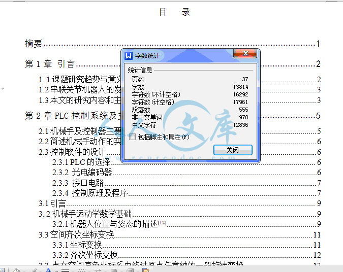
37页 13000字数+说明书+任务书+外文翻译+VB5程序【详情如下】
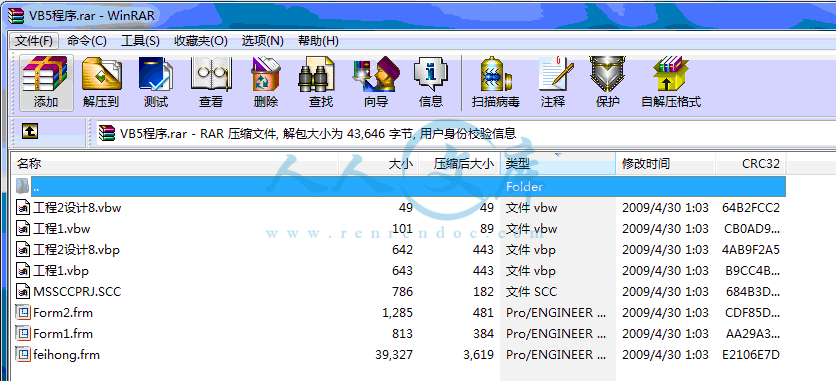
VB5程序.rar
任务书.doc
外文翻译--自动表面粗糙度同三维机器视觉和合作的机器人控制.doc
搬运机械手控制系统的设计说明书.doc
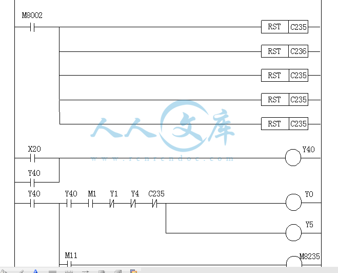
机械手控制程序梯形图.doc
评阅表.doc
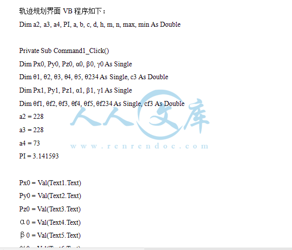
轨迹规划界面VB程序.doc


目 录
摘要 1
第1章 引言 2
1. 1课题研究趋势与意义 2
1.2串联关节机器人的发展和现状 3
1.3本文的研究内容和主要工作 3
第2章PLC控制系统及实现 5
2.1机械手及控制器主要参数 5
2.2简述机械手动作的实现 6
2.3控制软件的设计 6
2.3.1 PLC的选择 6
2.3.2 光电编码器 6
2.3.3 接口电路 7
2.3.4 控制原理及程序 7
3.1引言 9
3. 2机械手运动学数学基础 9
3.2.1机器人位置与姿态的描述[12] 9
3.3空间齐次坐标变换 11
3.3.1坐标变换 11
3.3.2齐次坐标变换 12
3.3 点在空间直角坐标系中绕过原点任意轴的一般旋转变换 13
3.4 Denavt-Hartenberg(D-H)表示法 15
3.4.1 坐标系的建立 15
3.4.2 几何参数定义 16
3.4.3 建立坐标系和坐标系的齐次变换矩阵 16
第4章 机器人运动学方程的求解 18
4.1机器人正向运动学 18
4.2 机器人逆向运动学 20
第5章 机械手轨迹规划 22
5.1 机器人轨迹的概念 22
5.2 轨迹的生成方式 22
5.2.1 轨迹规划涉及的主要问题 22
5.3 插补方式分类 23
5.4 机器人轨迹插值计算 23
5.4.1 三次多项式插值 24
5.4.2机械手轨迹规划。 25
第6章 系统交流界面设计 27
6.1Visual Basic6.0简介 27
6.2 VB设计任务 28
6.3 窗体设计 28
6.4窗体运行 29
参考文献 22
致谢 33
搬运机械手控制系统的设计
摘 要:本文运用运动学的研究方法建立了串联机械手运动模型,并用Visual Basic 6.0通过逆运动学对其运动轨迹的规划做分析。
首先,本文建立了参考坐标系和运动坐标系,给出串联机械手在这两个坐标系中的描述方法,并且定义了串联机械手的机构参数,以及相关数学知识的介绍。在此基础上,建立起了串联机械手的正解模型。机械手的动作过程由三菱公司生产的PLC实行控制。其次,通过利用串联机械手的逆解模型结论,对机械手的轨迹进行分析。此过程中 ,应用了功能强大的Visual Basic 6.0,进行自动运算,并利用其可视化功能做出简单人机交流界面,计算并显示出机械手的轨迹曲线,使得机械手的轨迹规划更为直观、易懂。
本文的研究工作对串联关节型机械手的设计具有一定的指导意义。运用本文的研究方法,可以有效提高机械手的设计质量和缩短设计周期。
关键词:机械手,正解模型,Visual Basic 6.0,PLC,轨迹规划
Design of Handing Manipulator Control System
Abstract:This paper studies the use of kinematic method of Tandem manipulator motion model, using Visual Basic 6.0 inverse kinematics through its trajectory planning to do the analysis.
First, this paper set up a reference coordinate system and coordinates movement, given the description of tandem manipulator in this two coordinates, and the definition of the series manipulator body parameters and the associated mathematical knowledge presentation. On this basis, established a series of positive manipulator model. Mechanical movement of the hands from the process of production of Mitsubishi Corporation PLC control. Secondly, through the use of serial manipulator inverse kinematics model concludes that the manipulator trajectory analysis. During this process, the application of the powerful Visual Basic 6.0, automatic operation, and the use of visualization functions made simple man-machine interface exchange, calculated and shown manipulator curves, make manipulator trajectory planning more intuitive, understandable.
The research of this paper is very useful for the chain-structured robot. it willimprove robot design quality and shorten the design time.
Key words:Manipulator, positive solution model, Visual Basic 6.0, PLC, trajectory planning
第1章 引言
1.1工业机器人的发展和现状
机器人是一种被设计用来移动物体、部件、工具或者特定设备的,可以重复编程、具有多种功能的操作器.它通过一系列可变的程控动作来完成各种各样的任务。通常工业机器人大致分为以下三类:
1) 串联结构机器人
2) 框架结构机器人
3) 并行机构机器人
从结构上看,并行结构机器人的运动平台通过相互关联的多个运动链与下平台相连,这使并行结构机器人具有刚性高、承载能力大和精度好等特点。它的主要缺点是控制复杂,使得它很难应用高阶控制方法,从而妨碍了这种机器人的应用。框架结构机器人工作空间比较小,操作灵活性受到限制。
串联结构机器人具有较大的工作空间和较高的运动灵巧度,常用的结构是串联关节形式,它采用串联链式结构和全关节驱动,容易建立运动学和动力学模型,可以采用一些先进的、实时的控制算法,其动作灵活,避障性好。由于串联结构机器人采用悬臂梁式的手臂结构和关联的驱动系统,使得该类机器人存在着一些固有缺陷如操作精度性欠佳,难以完全平衡,且运动存在耦合等问题,但总体数量目前应用越来越多。在本文中研究的机器人是串联机构机器人的一类一一串联关节机器人,如图1.1所示。这类机器人的基本结构是串联的六自由度开链式,关节相互垂直或平行,每个关节都有单独的驱动机构。前三个关节(包括基座、腰部和臂部)具有三个转动自由度,确定手部在空间的位置,这三个关节和联接他们的杆件所构成的机构称为机械手的位置机构;后三个关节(腕部)的主要功能是确定手部在空间的姿势,这三个关节和联接他们的杆件所构成的机构称作姿势机构。位置机构可基本确定机械手的工作空间范围,前三个关节的运动称作机械手的主运动;后三个关节的运动称作姿态运动,姿态机构主要确定机械手的工作姿态。所有的关节驱动器共同参与控制,来完成机械手的六自由度运动,以实现终端执行器按一定姿态到达工作空间的每个工作点,本文主要讨论除手指关节外的其它五个自由度。
串联关节机器人一般可用一个开环关节链来建模,此链由数个刚体(杆件)用驱动器驱动的移动或转动关节串联而成,开链的一端固接在基座上,另一端是自由的,安装着工具(终端执行器),用以操纵物体,或完成装配作业。这类机械手属于空间机构,运动通常只用转动和移动两类。用转动相联的关节成为转动关节;以移动相联的关节成为移动关节。单独驱动的主动关节数目成为机械手的自由度数。本文要研究串联关节机器人的五个关节都是转动关节。
随着技术的进步,串联结构机器人本体结构近10年来发展变化很快,从开始的含有局部闭链的平行四边形机构,到改变为大储采用新型的非平行四边形的单连杆机构,工作空间有所增加,本体自重进一步减小,变得更加轻巧,新材料的采用如轻质铝合金材料的应用,大大提高了机器人的性能,并逐渐成为串联结构机器人普遍采用的结构之一。
1.2课题的提出及意义
进入20世纪90年代以来,由于具有一般功能的传统工业机器人的应用趋向饱和,而许多高级生产和特种应用则需要具有各种智能的机器人参与,因而促使智能机器人获得较为迅速的发展。无论从国际或国内的角度来看,复苏和继续发展机器人产业的一条重要途径就是开发各种智能机器人,以求提高机器人的性能,扩大其功能和应用领域。回顾近10多年来国内外机器人技术的发展历程,可以归纳出下列趋势:
1)传感型智能机器人发展较快
2)开发新型智能技术
3)采用模块化设计技术
4)机器人工程系统呈上升趋势
5)微型机器人的研究有所突破
6)应用领域向非制造业和服务业扩展
从整个工业领域来看,对工业机器人需求越来越大,性能指标越来越高。运动学系统是工业机器人的底层核心部分,对其关键技术,如运动学建模、运动学方程的求解、运动空间插值算法等的研究,将从很大程度上决定着一个机器人系统的基本性能。随着科技的发展,机器人已成为工业的现代化程度的标志,机器人学是一门高度交叉的前沿学科,与机械学、生物学、人类学、计算机科学与工程、控制论与控制工程学、人工智能、社会学等。机器人学包含机器人运动学、机器人动力学、机器人控制、机器人智能化等领域有着不同层次意义的联系,本文以对机器手的控制及运动学系统为主线,对如何实现机器手动作作了较深入的研究与讨论。
总的说来,对于机器人控制及运动系统的研究在理论和应用上都具有重要的意义。本文基于上述的串联关节机器人为研究对象,对GR-1型教学机械手的运动及控制进行研究。
1.3本文的研究内容和主要工作
本文以GR-1型教学机械手为研究对象,对其进行运动学求解;并利用其结果对机械手的轨迹进行规划;最后利用其轨迹规划的结果,对机械手的运动进行自动控制。该内容由两人共同完成,本人具体完成以下工作:
1、对机械手进行位姿描述,应用D-H参数法建立串联关节机器人杆件坐标系,求解位姿正解。
2、对机械手的轨迹进行规划,采用三次多项式插值运算的方法,利用由机器人运动学解得的关节变量求得运动轨迹方程。
3、用Visual Basic 6.0软件做出人机交互界面,在界面上显示计算结果和轨迹曲线图。
4、编写机械手控制程序,通过Visual Basic 6.0界面将结果输出并将控制数据输入PLC,实现对机械手的自动控制。
第2章PLC控制系统及实现
2.1机械手及控制器主要参数
1 机械手
a、自由度:5(不包括手指开闭控制)
b、各关节活动范围:
腰: ≥
肩: ≥
肘: ≥270。
手俯仰: ≥
手指旋转:≥
c、最大活动区域:
垂直方向:850mm
水平方向:600mm
d、基本尺寸:
上、下臂长:228mm
手后部:73mm
e、各轴分辨率如表2-1:
表2-1 各轴分辨率参数
轴 电机代号 分辨率(度/脉冲)
躯干 M1 0.14
上臂 M2 0.11
下臂 M3 0.11
手俯仰 M4 0.11
手指旋转 M5 0.24
2 电机
工作电压:U = 12 V
空载转速:n = 3000 r/min
空载电流:I = 0.15 A
2.2简述机械手动作的实现
GR—1型教学机械手主要由机械和控制两大部分组成,本论文主要对其控制部分进行研究。
该机械手采用的是串联式关节机械手,全部采用开链式,结构简单,整个机械手分5个自由度:腰、肩关节、肘关节、腕关节和手指,全部有直流电机驱动。控制功能的实现主要是通过对控制器的编程,由光电编码器检测各电机的旋转角位移,再结合PLC来控制各个电机的角位移,从而实现对机械手各个关节较精确的运动以实现机械手预期的动作。
光电编码器起控制直流电机角位移精度作用,固定于电机转轴上与电机同步运转。系统工作时,各光电编码器输出一系列与直流电机运转角度相对应的脉冲信号,经转换电路将序列脉冲电压信号转换成PLC可以接收的开关信号,在PLC内部通过计数器计数后得到一个电机实际的角位移信号,运行PLC控制程序,获得确定输出,再通过外电路由PLC的输出信号来控制电机的启动停止,以实现机械手的预期动作。下面将对PLC如何控制直流电机来实现机械手动作实现的方案来做说明。
2.3控制软件的设计
实现PLC对机械手的控制,要将各杆件的运动控制转换成对机械手各电机角位移的控制。要使机械手手抓到达预期的位置就要计算出每个关节运动的角度,即每个电机所应转的角度,这可通过对各空间坐标系的相对运动在运动学基础上计算得到,最后,将其转换成PLC内部控制指令即可实现软件控制
2.3.1 PLC的选择
PLC类型的选择主要考虑两个方面:输入输出点的数目和存储容量。容量有计算公式:
指令条数=(输入点数+输出点数)(10--12)
再留有15%左右的备用量,根据外部电路的特点得到输入、输出点的数目,最后选定用三菱公司生产的FX2N—64MR型PLC。具体计算和分析过程参照同组同学毕业设计说明书。
2.3.2光电编码器
参考文献
1.刘极峰,益际明.机器人技术基础[M].北京:高等教育出版社,2006.
2.张铁,谢存喜.机器人学[M].广州:华南理工大学出版社,2003年.
3.从爽,李泽湘.实用运动控制技术[M].北京:电子工业出版社,2006.
4.钟肇新,范建东.可编程控制器原理及应用[M].广州:华南理工大学出版社,2003年.
5.俞建家.Visual Basic 6.0[M].福建:厦门大学出版社,2005年.
6.吕伟臣.Visual Basic 6.0 初级编程教程[M].北京:北京大学出版社,2002年.
7.龚沛曾.Visual Basic 程序设计教程[M].北京:高等教育出版社,2004年.
8.邓星钟.机电传动控制[M].武汉:华中科技大学出版社,2000年.
9.张海根.机电传动控制[M].北京:高等教育出版社,2005年.
10.大熊.机器人控制[M].北京:科学出版社,2002年.
11.丹尼斯.机器人设计与控制[M].北京:科学出版社,2004年.
12.刘极峰.计算机辅助设计与制造[M].北京:高等教育出版社,2004年.
- 内容简介:
-
湘 潭 大 学毕业论文(设计)任务书论文(设计)题目:搬运机械手控制系统的设计 学号: 姓名: 专业: 机械设计制造及其自动化 指导教师: 系主任: 一、主要内容及基本要求在本次搬运机械手控制系统的设计中,要完成的任务有如下几个方面: 1、用机器人运动学求得搬运机械手的正解; 2、由运动学方程解得搬运机械手各关节变量,并求出轨迹方程; 3、用VB建立人机交互界面,并根据轨迹方程画出轨迹曲线; 4、实现VB界面与PLC的通信,以及对搬运机械手的控制; 5、写一份8000字以上的毕业设计说明书; 6、一篇不少于3000单词的英文原文及中文翻译。 二、重点研究的问题1、搬运机械手运动学方程正解的求解; 2、建立VB界面,实现计算以及画出轨迹曲线; 3、实现搬运机械手的自动控制。 三、进度安排序号各阶段完成的内容完成时间1查阅资料07.3.1507.3.312总体反方案设计07.4.107.4.73搬运机械手的运动学位姿正解07.4.807.4.244学习Visual Basic软件,做交互界面04.4.2507.4.305编写程序,实现机械手运动的控制07.5.1.7.5.206写设计说明书07.5.2107.5.317准备答辩2007年6月初四、应收集的资料及主要参考文献1、刘极峰,易际明.机器人技术基础M.北京:高等教育出版社,2006年. 2、张铁.机器人学M.广州:华南理工大学出版社,2000年. 3、从爽.实用运动控制技术M.北京:电子工业出版社,2006年. 4、钟肇新,范建东.可编程控制器原理及应用M.广州:华南理工大学出版社,2003年 5、俞建家.Visual Basic 6.0程序设计与应用教程M.福建:厦门大学出版社,2003年 6、吕伟臣.Visual Basic 6.0初级编程教程M.北京:北京大学出版社,2002年. 7、大熊.机器人控制M.北京:科学出版社,2002年. 8、张海根.机电传动控制M.北京:高等教育出版社,2005年. 9、丹尼斯.机器人设计与控制M.北京:科学出版社,2004年. 10、刘极峰.计算机辅助设计与制造M.北京:高等教育出版社,2004年. 附录II 外文翻译自动表面粗糙度同三维机器视觉和合作的机器人控制Chris Marshall, Robert Bicker and Paul Taylor摘要:本文介绍了创新和务实的自动检测皮革表面粗糙度,利用结构光三维机器视觉对物体轮廓的知觉和NURBS插补准确和平稳轨迹生成。作为高压喷砂用于粗加工,要考虑空间限制,在爆破庭额外的自由度介绍利用一个转盘,它支持工件,协同控制是实施之间的一个六自由度机器人和转台尽量机器人动作在满足要求的变速控制,精确的轨迹跟踪和定位控制。实验结果一致的业绩已经显示出了该方法的有效性。关键词三维视觉;曲线曲面的非均匀有理B样条内插法;合作管理;机器人;表面粗糙度 1 、引言表面处理,特别适用于鞋类制造业,质量关键的大问题是为行业的生产鞋用水泥粘结和直接注塑鞋底。一个主要因素在于完整的胶合面,这就意味着要充分清除材料的表面,以促进市场的基本结构,或者在发生天然皮革的表皮。目前,表面处理等两种形式进行,采用了气缸钢丝刷或磨料表面旋转车轮或带;这是做手工应用的历时鞋面的旋转钢丝刷,或自动机适用该鞋面以钢丝刷控制四个或五个轴,显然,手工操作,需要高超的技巧,是难以维持在一个良好的水准,由于始终不断注意经营者。控制系统的自动化进程通常开环定位装置和过程控制是有限事先调整刷特点,如丝的刚度和敏锐性,转速和控制力量与毛笔适用。在过去十年中,研究工作已取得根本性改善的轨迹控制, 运用传感器和分析方法能够检测过程实时1,2,3,智能控制4,5的接触力,转速和进给速度的钢丝刷优化材料去除和表面纹理。大多数的这些努力都局限于实验室示威由于有实际困难的调谐有很大差异,在刷特色。因此,新工艺是可取推进素质表面处理技术。磨料爆破和喷丸有效而广泛采用的表面处理工艺去除缝针,提高强度和其它相关的表面制备应用。一系列的皮革表面筛选试验采用喷砂机根据不同的条件下在我们的实验室最近表现一致的材料去除性能。相对于这些方法用接触力控制,这是比较容易控制参数的喷砂工艺,如空气压力,速度砂粒流迁入表面距离喷嘴表面,而更重要表现较为一致,较不敏感的工艺参数变化。一个主要问题自动鞋上摔打,是如何衡量可靠的三维剖面上,并确定适当的粗径上,这使得机器人操纵粗工具加以引导沿着指定的速度。常规传感器所不具备足够的计算粗径的上表面因复杂几何概况,尤其是当今许多女人的时尚鞋。机器视觉是最适当的感官方法,在三维测量,而且越来越便宜,为双方研究和过程控制。以前的相关研究著作描述6,7在某种程度上成功地证明效力结构光机视觉在自动唯一和粘接上的应用。然而,与其建立了视觉系统的模型,固定价值尺度因素来计算鞋廓坐标从图像数据。本文将建立一个数学模型之间的图像数据和世界的坐标它可以大大提高精确度剖面测量。测量结果,从机器视觉一般是离散的位置坐标,从一个连续剖面上可重构,经分段直线段或通过复杂曲线插补。扫描数据是有限的分辨率,由于速度要求的装配线,并花费大量时间形象加工一幢医科相机使用的建议视觉系统扫描决议排列为5毫米,在脚背面积和2.5毫米的脚趾和足跟区。大多数工业机器人控制器的位置直流装置内置插值,使他们能够处理断面位置。然而,这些控制器通常采用串行通信传输数据和指令上位PC机和机器人控制器相对缓慢的更新率,它必然导致低精度和呆滞的动态响应。一个美洲豹760个工业机器人被重新利用多轴运动控制器与以太网通信和位置更新率 多达200余等高线模式,这可大大提高精度。鉴于先前的嵌入式插不再提供,非均匀有理B样条插补应用于重建顺利连续轨迹由离散路径坐标。NURBS插补提供了一个统一的代表性分析和自由型曲线,并明显优于线性插值常规数控机床和机器人通常使用。速度和加速度的连续性整个曲线是至关重要的特点,以避免急冲提案的机器人末端效应。表面喷砂进行内密封庭该机器人已在有限空间内操控粗喷嘴。为减少运动造成的机器人手臂,额外自由度引入到工件使鞋上支撑平台可以转动实时控制下。因此,协同控制算法所需要的7个自由度的冗余系统。保持一贯的表面处理性能,在某些砂粒空气流量,恒明或线速度的粗喷嘴相对的上表面是至关重要的,这一目标已经实现,开发新颖的NURBS轨迹生成算法和插值方法。2、三维机器视觉轮廓测量发达结构光扫描系统显示如图1;它包括一个模拟式摄像机,激光线发生器和步进电机驱动直线下滑提供扫描议案照相机和激光打印机。鞋将扫描是紧紧空气钳位在一个转盘是位于45度角的水平面。这种配置可以减轻媒体爆破积累了放在桌上的喷砂工艺。照相机和激光线发生器装在步进电机驱动直线下滑,与激光线垂直的转盘和一个夹角,照相机的光轴与激光线。客观的视觉系统,是提供一个三维轮廓的钳位鞋基于坐标系统定义的转盘,边鞋面,然后是发现和粗径是指形匹配的上唯一的。经过粗加工的道路,得到了 鞋钳位的转盘是运到爆破厅通过直线滑机器人操纵喷砂处理。图1 结构光视觉系统。如图2,存在两个坐标系,图像坐标系团与物体坐标系统哎哟,它们之间的关系需要加以确定的物理位置和方向的对象点提取图像数据。图像坐标系,是指与镜头的光轴作为ocz轴方向增加图像连续坐标ocy轴线,轴线的ocx决定用右手规则。物体坐标系是指与该中心的转盘出身,向下方向沿转盘和平行的直线滑携带激光照相机作为owz轴截至方向垂直于转盘作为owx轴线;owy可以定义方便用右手规则。结构光三维扫描钻机是精心,刻意设计,激光平面平行于xowy平面物体坐标系,使每一个点上的激光线相交的对象有一个固定的Z坐标对象坐标系因此,其他两个部件坐标X和Y可以单独确定从二维图像数据。图2 摄像机与世界坐标系统。数学关系的摄像机坐标系与物体坐标系中是不可或缺的连接二维 图像数据与三维物体的坐标。有很多方法8,9,10,11和12开发构建数学模型的视觉系统,其中蔡明亮的方法8,是最常采用的。一般来说,模拟视觉系统分为两阶段相关参数的外在和内在参数。外在参数描述空间关系中的两个坐标系,如平移和旋转变换的坐标系中的物体坐标系统可以映射到 摄像机坐标系; 这些转变可以在数学上表示为: (2)在这里,R是旋转矩阵定义的欧拉角,由TAIPEI,烃厝翻译沿新owx,owy和owz轴旋转。分子RI在矩阵R可以表示为功能旋转角度,如下: (3)成反比,欧拉角可确定由R: (4)第二阶段的模拟进程,是与照相机的内在参数:它是基于针孔相机的透视投影模型径向变形及其它异常现象的考虑。针孔相机的模式来改造点(圆度量,zc)在摄像机坐标系奥委会相关位置图像缓冲像素。这一阶段共分三个转变,第一次描述了变换从相机坐标(XC细胞度量,ZC)的失真,以二维传感器平面坐标(徐钰)由方程: (5)其中f是有效焦距的镜头。第二个层面的转变反映了径向几何失真,这是造成的镜头,其实这点在不同径向距离镜头轴线发生明显放大。坐标,在一个失真图像传感器飞机(徐钰),可从观测(扭曲)图像坐标(XD型,YD型) (6)在这里,是径向距离观测点的摄像机光轴,K1的是系数的径向畸变。 最后的变换叙述关系的观察阵地的图像传感器平面坐标,在缓冲图像帧,它被描述的: (7)而泰航与CY是像素坐标相交光轴与传感器平面,DX的镝的有效培训中心之间的距离照相机的传感器组成,在第十和昌方向分别S、X的,是一个尺度因子,以弥补任何不确定的数目比例分子传感器关于CCD和象素数目在照相机的帧缓冲X方向。所以关系的对象坐标和图像数据相结合,建立了有效性。(1),(5),(6),(7)在一起。照相机的模型所述标定需要确定的外部和内部参数,然后它可以把图像数据用来作为坐标在转台坐标系。用标定目标,并根据Tsai的方法,建议的摄像系统标定以及由此产生的参数有: 3、合作机器人控制图3显示了成立机器人鞋上喷砂, 其中喷砂嘴,是他操纵的机器人末端微跟随造成粗径与某些方向。一个金属盘,并采取适当的薰陶作为掩模的路径跟踪,以防止流砂从 破坏以外地区的皮革表面。双方轨迹跟踪和定位控制的机器人末端效应可引起较大规模的联合运动。作为喷砂会发生议事堂,机器人动作应限制在一个受约束的小空间。 为了减少机器人动作,额外的自由度,旋转 引入到鞋面支持转台,这不可避免地导致了冗余系统七个自由度。图3 机器人鞋上喷砂成立的。一个简单的协同控制策略适用于转盘和机器人系统,旨在减轻关节运动。算法是描图。B和C是坐标的粗径产生NURBS插补,角度,可据此计算,同样的计算,可以做到对所有插值点的路径。简单地转动转盘角度,以,分别可以带多点,B和C上的X轴为中心的A1,B1和C1组,同样,所有坐标的轨迹,这可以大大降低运动的机器人。理论上,有没有运动,在y方向做一系列动作,在X方向不会改变,小的方向变化的最终效应在Z轴方向高度变化。4、结论本文描述了一种新的自动皮革技术,它利用空气助推喷砂表面处理表面粗度,三维机器视觉物体轮廓测量,NURBS曲线插补轨迹重建和工业机器人的自动操纵和控制。一个数学模型的形象,制度的建立及相关参数进行了校准,这大大提高了测量精度。平稳轨迹的作品再现,由离散图像数据的NURBS曲线插补基于这个原因,泰勒的二阶逼近扩张被用来执行速度控制的机器人末端效应。顺利机器人准确地跟踪目标。协同控制实施机器人与工件支持平台,以最小的机器人动作。实验结果一致的表面处理表现的效率的方法。 可以进一步改进,采用高帧频摄像机结合标定的视觉系统登记的机器人末端微向工件平台和工艺优化。附录III 外文原文Automatic surface roughing with 3D machine vision and cooperation robot controlChris Marshall, Robert Bicker and Paul TaylorAbstractThis paper presents an innovative and practical strategy for automated leather surface roughing, using structured light 3D machine vision for object profile perception, and NURBS interpolation for accurate and smooth trajectory generation. As high pressure grit blasting is used for roughing, considering the spacial constraints in the blasting chamber, an additional degree of freedom is introduced using a rotary table, which supports the workpiece. Cooperative control is implemented between a 6-DOF robot and the rotary table to minimize robot movements, while satisfying the requirements of variable velocity control, accurate trajectory tracking and orientation control. Experimental results of consistent roughing performance have shown the efficiency of the proposed method.Keywords: 3D vision; NURBS interpolation; Cooperative control; Robot; Surface roughing 1. Introduction In surface treatment with particular application in the footwear manufacturing industry, the quality of sole bond is a major problem for the sectors that manufacture shoes with cement bonded and direct injection moulded soles. A main factor in the integrity of the sole bond is the preparation of the mating surfaces, which means to remove the surface of the material adequately so as to facilitate a bond to the underlying structure of the upper material, or in the case of natural leather to the epidermis. Currently, surface treatment is carried out either by means of a cylinder wire brush or an abrasive surface on a rotating wheel or band; this is done either by manual application of the lasted shoe upper to the rotating wire brush, or an automatic machine that applies the shoe upper to the wire brush by control of four or five axes. Obviously, manual operation requires great skills and is difficult to maintain at a good standard consistently due to constant attention by the operator. The control systems for the automatic process are generally open loop positional devices, and the process control is limited to prior adjustment of brush characteristics such as wire stiffness and sharpness, speed of rotation and control of force with which the brush is applied. During the last decade, research efforts have been made on making fundamental improvements to the path control, applying sensor and analysis methodology capable of inspecting the process in real time1, 2 and 3, intelligent control4 and 5 of the contact force, rotation speed and feed rate of the wire brush to optimize material removal and surface texture. Most of these efforts were limited to laboratory demonstrations due to practical difficulties of tuning the large variations in brush characteristics. Consequently, new process technology is desirable to advance the quality of surface treatment. Abrasive blasting and shot peening are effective and widely used surface treatment processes for the removal of sharp edges, improvement of strength and other related surface preparation applications. A series of leather surface screening experiments using a grit blasting machine under distinct conditions undertaken in our laboratory recently have shown consistent material removal performance. Comparing with those methods using contact force control, it is much easier to control parameters of the grit blasting process, such as air pressure, velocity of grit flow moving across the surface and distance from the nozzle to the surface and, more importantly, the performance is more consistent and less sensitive to process parameters variations. A major problem for automatic shoe-upper roughing is how to reliably measure the 3D profile of the upper, and define a proper roughing path on it, this enables the robot manipulated roughing tool to be guided along the path with specified velocity. Conventional sensors are not sophisticated enough to calculate the roughing path on the upper surface due to the complex geometrical profile, particularly many of todays womens fashion shoes. Machine vision is the most appropriate sensory methodology in 3D measurement, and is becoming more affordable both for research and in-process control. Previous related research works described in6 and 7 have to some extent successfully demonstrated the effectiveness of structured light machine vision in the automatic sole and upper bonding application. However, instead of establishing the vision systems model, fixed value scale factors were used to calculate the shoe profile coordinates from image data. This paper will establish a mathematical model between the image data and the world coordinates, which can greatly improve precision of profile measurement. Measurement results obtained from machine vision are generally discrete position coordinates, from which a continuous profile can be reconstructed, either via piecewise straight line segments or through complex curve interpolation. Scan data are of limited resolution due to velocity requirements of the assembly line and the time spent on image processing. For a 25fps camera used in the proposed vision system, the scan resolutions are arranged as 5mm at the instep area and 2.5mm at the toe and heel areas. Most industrial robot controllers are positional servo devices with embedded interpolation, which makes them capable of dealing with positional discontinuities. However, these controllers usually use serial communication to transfer data and commands between the host PC and the robot controller with a relatively slow update rate, which inevitably leads to low accuracy and sluggish dynamic response. A PUMA 760 industrial robot was reengineered using a Galil multi-axes motion controller with Ethernet communication and position update rate up to 2ms in contour mode, this can significantly improve precision. As the previous embedded interpolation is no longer available, Non-Uniform Rational B-Spline interpolation is applied to reconstruct a smooth continuous trajectory from discrete path coordinates. NURBS interpolation provides uniform representation of both analytical and free-form parametriccurves, and has significant advantages over linear interpolation that conventional CNC machines and robots usually use. Velocity and acceleration continuities throughout the whole parametric curve are vital characteristics to avoid jerky motions of the robot end-effector. Surface grit blasting is carried out inside a sealed chamber, in which the robot has limited space to manipulate the roughing nozzle. In order to minimize motion of the robot arm, an additional degree of freedom is introduced to the workpiece, so that the shoe-upper support platform can rotate under real time control. Therefore, cooperative control algorithms are necessary for the 7degrees of freedom redundant system. To maintain consistent surface treatment performance under certain air grit flow rates, constant or prescribed line velocity of the roughing nozzle relative to the upper surface is vital, this has been achieved by development of novel NURBS trajectory generation algorithm and interpolation methods. The rest of the paper is organized as follows: description of the 3D vision system for shoe upper profile measurement is given in Section2; NURBS interpolation for smooth trajectory reconstruction from discrete scan data is placed in Section3; variable feed rate NURBS interpolator for the robot can be found in Section4; experimental grit blasting results is given in Section5. 2. 3D machine vision for profile measurement The developed structured light scanning system is shown in Fig.1; it consists of an analogue camera, laser line generator and stepper motor driven linear slide providing scanning motions for the camera and laser. The shoe to be scanned is tightly air clamped on a rotary table which is located at an angle of 45 degrees to the horizontal plane. This configuration can alleviate blasting media accumulating on the table during the grit blasting process. The camera and laser line generator are mounted on the stepper motor driven linear slide, with the laser line perpendicular to the rotary table and an angle between the cameras optical axis and the laser line. The objective of the vision system is to provide a 3D profile of the clamped shoe based on a coordinate system defined on the rotary table, edge of shoe upper is then detected and roughing path is defined by conformal matching of the upper and sole. After the roughing path is obtained, the shoe clamped on the rotary table is delivered into the blasting chamber through a linear slide for robotic manipulated grit blasting treatment. Fig.1.Structured light vision system.As illustrated in Fig.2, there exist two coordinate systems, the image coordinate system OC and object coordinate system OW, between them a relationship needs to be established to determine the physical position and orientation of object points from extracted image data. The image coordinate system is defined with the cameras optical axis as OCZ axis, the direction of increasing image row coordinates as OCY axis, and OCX axis is decided using the right-hand rule. The object coordinate system is defined with the centre of the rotary table as origin, downwards direction along the rotary table and parallel to the linear slide carrying the laser and camera as OWZ axis, up direction vertical to the rotary table as OWX axis; OWY can be defined conveniently using the right-hand rule. The structured light 3D scanning rig is carefully and deliberately designed that the laser light plane is parallel to the XOWY plane in the object coordinate system, so that each point on the laser line intersecting with the object has a constant z coordinate in the object coordinate system, therefore the other two coordinate components x and y can be solely determined from the 2D image data. Fig.2.Camera and world coordinate systems.The mathematical relationship between the camera coordinate system and the object coordinate system is vital and essential which connects 2D image data with 3D object coordinates. There are a number of methods8, 9, 10, 11 and 12 developed to construct a mathematical model for the vision system, among which, Tsais methodology8 is most commonly applied. In general, modelling of a vision system consists of two stages related the extrinsic parameters and intrinsic parameters. The extrinsic parameters describing the spatial relationship of the two coordinate systems, such as the translational and rotational transformations by which coordinates in the object coordinate system can be mapped to the camera coordinate system;these transformations can be expressed mathematically as: (2)here, R is the rotation matrix defined by the Euler Angles , TX,TY and TZ are translations along the new OwX, OwY and OwZ axis after rotation respectively. Elements ri in matrix R can be expressed as function of rotation angles , , and as follows: (3)Inversely, Euler angles can be determined from R by: (4)The second stage of the modelling process is related to the cameras intrinsic parameters: it is based on the pinhole cameras perspective projection model with radial distortion and other aberrations taken into account. Pinhole cameras model is used to transform point (XC,YC,ZC) in the camera coordinates system OC to associated position (Xf,Yf) in the image buffer in pixels. This stage consists of three transformations, the first one describes the transform from camera coordinates (XC,YC,ZC) to undistorted 2D sensor-plane coordinates (XU,YU) by equation (5)where f is the effective focal length of lens. The second transformation reflects the geometric radial distortion of the lens, which is caused by the fact that points at different radial distance from the lens axis undergo distinct magnifications. The coordinates in an undistorted image sensor plane (XU,YU) can be obtained from the observed (distorted) image coordinates (XD,YD) by (6)here, is the radial distance from the observed point to the camera optical axis, k1 is the coefficient of radial lens distortion. The final transformation describes the relation between observed positions on the image sensor-plane to coordinates (Xf,Yf) in the image frame buffer, which is described by: (7)where CX and CY are the pixel coordinates of the intersection of the optical axis and the sensor-plane, dX and dY are the effective centre to centre distances between the cameras sensor elements in the XC and YC directions respectively, and SX is a scaling factor to compensate for any uncertainty in the ratio between the number of sensor elements on theCCD and the number of pixels in the cameras frame buffer in the X direction. Therefore the relationship between the object coordinates and image data is established by combining Eqs. (1), (5), (6) and (7) together. The cameras model described above need calibration to identify the exterior and interior parameters before it can be used to convert image data (Xf,Yf) into coordinates in the rotary table coordinate system. Using a calibration target and according to Tsais method, the proposed camera system is calibrated and resulting parameters are: To calculate 3D objects coordinate from 2D image data (Xf,Yf) using the vision systems model constructed above, the constraint imposed on the ZW coordinate when the laser line intersects with the object is used together with model Eq. (1) to determine a unique world coordinate (xw,yw,zw). For simplicity, in this design, the laser beam is adjusted to be critically vertical to the rotary table or parallel to YWOWZW plane, so that all ZW coordinates of intersection points on the laser line are constant. In this case, two high precision linear slides and one rotary table manufactured by Parker were used, to adjust and verify the perpendicularity of the laser light sheet with the rotary table, during the whole motion range of the laser and camera linear slide, make sure the image of the laser line intersecting the rotary table is horizontal. Therefore, world coordinates can be calculated from image data by equation as follows: (8)Discrete shoe profile coordinates are obtained by image processing to find the edge points and conformal matching of the shoe upper and sole for further fine trim, two angles that define the shoe upper surface are also calculated from neighbouring edge points and individual scan line. Detailed description of the strategy can be found in13 published by the authors. Fig.3 shows an example 3D shoe profile consists of discrete points extracted from the laser scanning process. Fig.3.Measurement of shoe upper contour trajectory.3. NURBS interpolation for trajectory production 3.1. NURBS curve interpolation NURBS is an acronym for Non-Uniform Rational B-Splines, they provide a single precise mathematical method for describing common analytical shapes including lines, planes, conic curves, free-form curves, quadratic and sculptured surfaces. The one dimension B-Spline curve is defined over a free parameter 0u1 by the following equation: (9)The point on the curve at the parameter value u is denoted by P(u), which is a weighted average of all the control points denoted by Pi, the blending function or basis function Ni,k(u) decides the extent to which a particular control point controls the curve at a particular parameter value u. The basis function Ni,k(u) depends on the parameter value u and the order of the curve k, and is recursively defined as follows: (11)the constants u0,un+k, called knot values, are specific instances of the parametric value u, and are strictly in nondecreasing order. The order of a NURBS curve defines the number of nearby control points that influence any given control point, generally, high order interpolation leads to smoother curve recreation. If the knot values are decided so that u1u0=u2u1=un+kun+k1, then all the basis functions are of identical shape and every control point has identical effect on the resulting parametric curve; this is called Uniform B-spline, otherwise, Non-Uniform. Introducing an additional term, weight of the control point, will allow B-spline to represent conics and any other free-form curves and surfaces, and have more control over the shapes. The resulting curves, with a weight for each control point, are called rational curves. Therefore, a Non-Uniform Rational B-spline curve is defined by the formula: (13)where Ri,k(u) is the single rational B-spline, which denotes the extent to which the control point has control over the curve. NURBS curve interpolation, combined with basic approximation principles for parametric curves such as first and second order Taylor series expansion, has successfully been utilised in real time CNC variable feed rate command generation14, 15, 16, 17 and 18, robot control19, 20, 21 and 22 and computer graphics. In this work it is used for the reconstruction of a continuous profile model from discrete scan data; Fig.4 shows the result of a 12th order NURBS interpolation of shoe-upper profile. As described in the above sections, NURBS is expressed in relatively complex equations; the higher the order, the more complex, and therefore the more computationally intensive. However, simple conventional piecewise linear interpolation or polynomial spline interpolation either leads to velocity and acceleration discontinuities at the junction of line segments or is unable to represent free form curves and therefore cause significant deviation from original data points. Fig.5 shows velocity profile calculated from third order NURBS interpolation, and there exist high velocity fluctuations. In this work, the interpolation calculation is implemented offline after discrete data points are obtained from image processing; thus intensive computation is not a critical issue. Fig.4.3D trajectory from NURBS curve interpolation.Fig.5.Velocity plot from 3 order NURBS interpolation.3.2. Command generator for robot controller By using NURBS interpolation, smooth trajectory has been achieved from discrete image data, which is represented in parametric form in three-dimension space in terms of a free parameter u: (14)The redesigned robot controller consists of several-position servo devices, which control each robot joint according to position increments received from the command generator. Velocity control of the robot end-effector is critical not only because it is essential formaterial removal control during the grit blasting process, but also because significant acceleration changes will cause mechanical vibrations. For simplicity, the robot dynamics was not considered in this work, based on the assumption that coordinated control of robot end-effector and rotary table can reduce the end effectors orientation change to a minimum value, and velocity commands generated by NURBS interpolation and Taylor approximation are relatively smooth, so that they dont exceed the robot dynamic constraints. In practice, with a 4ms robot sampling time, the proposed control method can achieve absolute velocity of 100mm/s without causing a vibration problem. To further improve processing speed and efficiency, strategies of time optimal control proposed in19 and21 can be applied. The key to velocity control of the robot end effector is to provide appropriate position increments in the cartesian coordinate during each sampling interval such that the ratio of the position increment and the sampling time equal to the prescribed velocity, based on NURBS interpolation of the desired trajectory and prescribed velocity profile of robot end effector. Although the NURBS curve is parametric and has continuous first and second order derivatives over parameter u, there is not a linear relationship between this parameter and the distance along the curve. Segmentation of the curve should be based on the required lengths of curve segments rather than equal parameter increments, accordingly, curve approximation is needed to determine successive values of u such that the lengths of curve segments are constant or proportional to the prescribed velocity profile. Line velocity along the curve in a three-dimension space can be expressed as follows: (15)and (16)Therefore, solution to parameter u for a specified line velocity along the curve can be found via the equation below: (17)However, a solution to the above equation is difficult in the general case; a computational efficient solution of Eq. (17) based on Taylors expansion approximation is used. The Taylors expansion up to second order is given by: (18)In the case that the sample time T is little, and the trajectory does not have a small radius of curvature, the first order approximation is usually adequate. However, considering the high curvature of the shoe upper particularly at the toe and heel areas, two terms of Taylors expansion were used to provide approximation of higher precision. Second order derivative of parameter u over time: (19)here (20)if substituting Eq. (16) into (19): (21)If substituting Eqs. (17) and (21) into (18): (22)here, K=0,1,n, indicating the kth segmented curve. Using the velocity profile derived in the first section, the next command parameter can be calculated using the above equation. 3.3. Velocity control for NURBS generated trajectory A trapezoidal velocity profile was used as the desired motion profile to achieve smooth motion of the robot end effector, enabling more accurate path tracking. The PUMA 760 robot controller was upgraded using a GALIL multi-axis motion controller with Ethernet communication for data communication between a host computer and the robot controller. The sampling rate for robot command updating depends mainly on the motion controllers servo update rate which is an order of 2ms. Here the robot command update rate is set to 4ms, which is a significant improvement to the 28ms updating rate of the original PUMA 760 controller. Second order Taylors expansion approximation of the interpolated trajectory is implemented to generate the parameter sequence u(0),u(1),u(n), which maintains a desired velocity profile as appropriate for surface grit blasting treatment. As shown in Fig.6, a high accuracy calculation of the velocity tracking is achieved, the velocity fluctuation is contained to be within 2% of the desired speed, which is adequate
- 温馨提示:
1: 本站所有资源如无特殊说明,都需要本地电脑安装OFFICE2007和PDF阅读器。图纸软件为CAD,CAXA,PROE,UG,SolidWorks等.压缩文件请下载最新的WinRAR软件解压。
2: 本站的文档不包含任何第三方提供的附件图纸等,如果需要附件,请联系上传者。文件的所有权益归上传用户所有。
3.本站RAR压缩包中若带图纸,网页内容里面会有图纸预览,若没有图纸预览就没有图纸。
4. 未经权益所有人同意不得将文件中的内容挪作商业或盈利用途。
5. 人人文库网仅提供信息存储空间,仅对用户上传内容的表现方式做保护处理,对用户上传分享的文档内容本身不做任何修改或编辑,并不能对任何下载内容负责。
6. 下载文件中如有侵权或不适当内容,请与我们联系,我们立即纠正。
7. 本站不保证下载资源的准确性、安全性和完整性, 同时也不承担用户因使用这些下载资源对自己和他人造成任何形式的伤害或损失。

人人文库网所有资源均是用户自行上传分享,仅供网友学习交流,未经上传用户书面授权,请勿作他用。
 川公网安备: 51019002004831号