论文.doc

喷墨打印机盒盖注塑模具设计【10张CAD图纸+WORD毕业论文】【注塑模具类】

收藏

压缩包内文档预览:(预览前20页/共60页)
预览图 预览图 预览图 预览图 预览图 预览图 预览图 预览图 预览图 预览图 预览图 预览图 预览图 预览图 预览图 预览图 预览图 预览图 预览图 预览图
编号:438265    类型:共享资源    大小:5.46MB    格式:RAR    上传时间:2015-06-02 上传人:好资料QQ****51605 IP属地:江苏
45
积分
关 键 词:
喷墨打印机 盒盖 注塑 模具设计 cad 图纸 word 毕业论文 模具
资源描述:

摘要

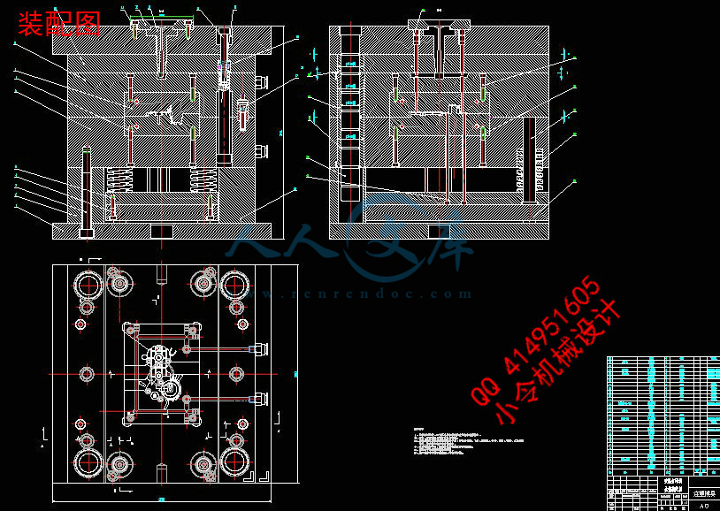
本设计为打印机盒盖注塑模的设计。设计中采用一模一腔,浇口采用点胶口,分型面选在截面最大处,塑件成型后利用推杆将成型制品从动模上推出,回程时利用复位杆复位。

设计中需要对塑件的尺寸进行计算,确定尺寸精度,然后进行注射机的初步选取。以及对注塑机的浇注系统、成型零件的结构、成型零件的尺寸、脱模推出机构、排气系统、温度调节系统进行了设计与计算。并且对注射机参数进行校核,包括模具闭合厚度、模具安装尺寸、模具开模行程、注射机的锁模力等。各个参数都满足要求后才能确定注射机的型号。

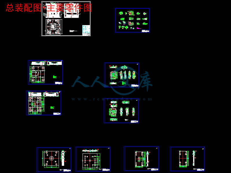
在设计过程中,为了更清楚的表达模具的内部结构,因此附有动模镶块、定模镶块、定模推板的二维零件图和模具三维爆炸图。


关键词:打印机盒盖;分型面;浇口;工艺分析


Ink jet printer cover injection mold design

Abstract

This design is the design of injection mould for the cabinet. The design uses two mold cavity, type of the sprue is latent gate, the parting surface is chosen in the maximum section of the plastics. After plastics are molded, molding products are driven by putting from dynamic model,then using reset stem returned.

In the design ,The need to calculate the size design, determine the size precision, the preliminary selection and the injection machine. And the injection molding machine of gating system, forming part of the structure, forming part of the size, mold release mechanism, exhaust system, temperature control system design and calculation. And to check the injection machine parameters, including the thickness of mold closing, mold installation size, mold opening stroke, the clamping force injection molding machine etc.. All the parameters meet the requirements to determine the type of injection machine.

In the design process, in order to express more clearly the internal structure of the mold, so a moving die insert, fixed die insert, the fixed mould push plate 2D part drawing and 3D map explosion.


Keywords: Cabinet;Parting;surface;Runner;Process analysis  


目  录

1 绪论……………………………………………………………………………1

1.1 题目背景………………………………………………………………………1

1.2 题目国内外相关研究情况……………………………………………………1

 1.2.1 国内研究的情况…………………………………………………………1

 1.2.2 国外研究情况……………………………………………………………2

1.3中国与国外先进技术的差距…………………………………………………2

1.4塑料模具发展走势……………………………………………………………2

2 产品分析……………………………………………………………………4

2.1 塑件分析……………………………………………………………………4

 2.1.1结构分析…………………………………………………………………4

 2.1.2尺寸精度分析……………………………………………………………5

 2.1.3 塑件厚度检测……………………………………………………………5

 2.1.4 表面质量分析……………………………………………………………5

2.2 塑件材料选择………………………………………………………………6

 2.2.1 物理性能…………………………………………………………………6

 2.2.2 ABS的主要性能指标…………………………………………………6

 2.2.3 ABS成型塑件的主要缺陷及消除措施…………………………………6

3 拟定模具结构形式及注射机的初步选择………………………………7

3.1 分型面位置的确定…………………………………………………………7

3.1.1模具的分型面…………………………………………………………7

3.1.2 分型面的确定…………………………………………………………7

3.2 塑件相关计算……………………………………………………………8

 3.2.1塑件相关计算…………………………………………………………9

3.3 型腔数量的确定…………………………………………………………10

3.4 初步选择注塑机…………………………………………………………11

4 浇注系统的设计……………………………………………………………13

4.1浇注系统 ……………………………………………………………………13

4.1.1浇注系统的作用………………………………………………………13

4.1.2 浇注系统布置…………………………………………………………13


4.2 浇注系统设计…………………………………………………………13

4.2.1 浇口套的设计…………………………………………………………13

4.2.2 浇注系统的设计………………………………………………………16

4.2.3 分流道与浇口…………………………………………………………17

4.3 浇口设计……………………………………………………………………18

  4.3.1 浇口的类型………………………………………………………………18

  4.3.2 浇口的位置 ……………………………………………………………18

5 成型零件的工作尺寸计算……………………………………………20

5.1 成型零件工作尺寸的计算………………………………………………20

6 成型零件结构设计…………………………………………………………24

6.1 PRO/E中的模具模块设计………………………………………………24

 6.1.1 凹模结构设计……………………………………………………………25

 6.1.2 凸模结构设计…………………………………………………………25

7导向机构设计………………………………………………………………27

7.1导向机构………………………………………………………………………27

 7.1.1 导柱…………………………………………………………………27

 7.1.2 导套………………………………………………………………………28

 7.1.3 导柱与导套的配用………………………………………………………29

 7.1.4 导柱布置…………………………………………………………………30

7.2 定位装置…………………………………………………………………30

 7.2.1 拉杆………………………………………………………………………30

7.3 尼龙开闭器装置……………………………………………………………30

8 脱模推出机构的设计………………………………………………………32

8.1 在设计脱模推出机构是应遵循下列原则…………………………………32

8.2 脱模力的计算……………………………………………………………32

8.3 推出机构设计……………………………………………………………32

 8.3.1 推杆布置…………………………………………………………………32

 8.3.2推杆结构及固定………………………………………………………33

 8.3.3 推杆强度交核……………………………………………………………33

8.4 拉料机构…………………………………………………………………34

9 排气系统设计……………………………………………………………36

10 温度调节系统设计………………………………………………………37

10.1 对温度调节系统的要求…………………………………………………37

10.2 冷却系统设计……………………………………………………………37


 10.2.1 冷却回路的布置………………………………………………………37

 10.2.1 设计原则………………………………………………………………37

 10.2.2 冷却时间的确定…………………………………………………38

10.3 模具冷却系统的计算…………………………………………………39

11 注塑机的校核………………………………………………………………40

11.1 最大注塑量的校核………………………………………………………40

11.2 锁模力的校核 ……………………………………………………………40

11.3 喷嘴尺寸校核……………………………………………………………40

11.4 定位圈尺寸校核……………………………………………………………41

11.5 模具外形尺寸校核………………………………………………………41 11.6 模具厚度校核……………………………………………………………41

11.7 模具安装尺寸校核………………………………………………………41

11.8 开模行程的校核……………………………………………………………41

12 模具工作过程……………………………………………………………43

12.1 模具总体结构………………………………………………………………43

12.2 开合模动作…………………………………………………………………45

13 模具可行性分析…………………………………………………………46

13.1 本模具的特点……………………………………………………………46

13.2 市场效益及经济效益分析…………………………………………………46

结论……………………………………………………………………………… 47致谢…………………………………………………………………………… 48

参考文献……………………………………………………………………… 49

毕业设计(论文)知识产权声明…………………………………………… 50

毕业设计(论文)独创性声明………………………………………… 51

附录………………………………………………………………………………52


1 绪论

1.1 题目背景

近年来,我国塑料模具业发展相当快,目前,塑料模具在整个模具行业中约占30%左右,而在整个塑料模具市场以注塑模具需求量最大。随着模具制造行业的发展,许多企业开始追求提高产品质量及生产效率,缩短设计周期及制造周期,降低生产成本,最大限度地提高模具制造业的应变能力等目标。新兴的模具CAD技术很大程度上实现了企业的愿望。近年来,CAD技术的应用越来越普遍和深入, 大大缩短了模具设计周期, 提高了制模质量和复杂模具的制造能力[][1]。

1.2题目国内外相关研究情况

1.2.1 国内研究的情况

80 年代以来,在国家产业政策和与之配套的一系列国家经济政策的支持和引导下,我国模具工业发展迅速,年均增速均为13%,在未来的模具市场中,塑料管件在模具总量中的比例还将逐步提高。经过半个世纪的发展,模具水平有了较大提高。在塑料管件模具方面已能生产19 万吨,上规模,高水平的企业越来越多,由于他的抗腐蚀、廉价等优秀品质,被应用于我国现代化建设的各个领域。精密塑料模具方面,已能生产医疗塑料件模具、多型腔小模数齿轮模具及塑封模具。所生产的这类塑件的尺寸精度、同轴度、跳动等要求都达到了国外同类产品的水平。还能生产厚度仅为0.08mm的一模两腔的航空杯模具和难度较高的塑料门窗挤出模等等。注塑模型腔制造精度可达0.02mm~0.05mm表面粗糙度Ra0.2μm模具质量、寿命明显提高了。非淬火钢模寿命可达10~30 万次。淬火钢模达50~1000 万次,交货期较以前缩短,但和国外相比仍有较大差距。成型工艺方面,多材质塑料成型模、高效多色注射模、镶件互换结构和

抽芯脱模机构的创新方面也取得较大进展。气体辅助注射成型技术的使用更趋成熟,如青岛海信模具有限公司、采用内热式或外热式热流道装置,少数单位采用具有世界先进水平的高难度针阀式热流道模具。但总体上热流道的采用率达不到10%,与国外的50%~80%相比,差距较大。在制造技术方面,CAD/CAM/CAE 技术的应用水平上了一个新台阶,陆续引进了相当数量的CAD/CAM 系统,如美国EDS 的UGⅡ、美国Parametric Technology 公司的Pro/Emgineer 软件等等[][2]。这些系统和软件的引进,实现了CAD/CAM 的集成,并能支持CAE 技术对成型过程,取得了一定的技术经济效益,促进和推动了我国模具CAD/CAM 技术的发展。

1.2.2 国外研究情况

   我国模具生产厂中多数是自产自配的工模具车间、分厂自产自配比例高达60%左右,而国外模具超过70%属商品模具。专业模具厂大多是“大而全”、“小而全”的组织形式,而国外大多是“小而专”、“小而精”。国内大型、精密、复杂、长寿命的模具占总量比例不足30%而国外在50%以上。2004年,我国模具进出口之比为3.7:1,进出口相抵后的净进口额达13.2亿美元,为世界模具净进口量最大的国家。注塑成型是最大量生产塑料制品的一种成型方法。二十多年来,国外的注塑模CAD 技术发展相当迅速。70年代已开始应用计算机对熔融塑料在圆形、管形和长方形型腔内的流动情况进行分析。80 年代初,人们成功采用有限元法分析三维型腔的流动过程,使设计人员可以依据理论分析并结合自身的经验,在模具制造前对设计方案进行评价和修改,以减少试模时间,提高模具质量。近十多年来。

注塑模CAD 技术在不断进行理论和试验研究的同时,十分注意向实用化阶段发展,一些商品软件逐步推出,并在推广和实际应用中不断改进[][3]。

1.3中国与国外先进技术的差距

面对国外先进技术与高质量制品的挑战,中国塑模企业不仅要加快产业集群化,发挥规模效应,还要注重模具产业链的前端研发、人才建设和产业链后端的检测以及信息服务,尽快缩短技术、管理、工装水平与国际水准的差距。这是塑料模具企业在发展中必须解决的重要问题。并且也要注意当前整个工业生产的发展特点(产品品种多、更新快、市场竞争激烈)[][4]。为了适应用户对模具制造的短交货期、高精度、低成本的迫切要求,我们必须学习国外先进技术,改善我们操作和管理方面的各种问题。

内容简介:
ORIGINAL ARTICLEA scaffolding architecture for conformal cooling designin rapid plastic injection mouldingK. M. Au&K. M. YuReceived: 4 August 2005 /Accepted: 25 March 2006 / Published online: 8 June 2006#Springer-Verlag London Limited 2006Abstract Cooling design of plastic injection mould isimportant because it not only affects part quality but alsothe injection moulding cycle time. Traditional injectionmould cooling layout is based on a conventional machiningprocess. As the conventional drilling method limits thegeometric complexity of the cooling layout, the mobility ofcooling fluid within the injection mould is confined.Advanced rapid tooling technologies based on solid free-form fabrications have been exploited to provide a time-effective solution for low-volume production. In addition,research has made attempts to incorporate conformalcooling channel in different rapid tooling technologies.However, the cooling performance does not meet the mouldengineers expectations. This paper proposes a novelscaffold cooling for the design of a more conformal andhence more uniform cooling channel. CAD model forconstructing the scaffolding structure is examined andcooling performances are validated by computer-aidedengineering (CAE) and computer fluid dynamics (CFD)analysis.Keywords Conformalcooling.Scaffolding.Rapidtooling.Plastic injectionmoulding1 Background on cooling channel design in plasticinjection mouldIn recent years, rapid prototyping and tooling 1 pro-cesses have found widespread use in speeding up toolingproduction. These processes greatly reduce the manufac-turing cost and the lead time required for tool produc-tion. Figure 1 illustrates the difference between traditionaltoolingproductionandcontemporaryrapidtoolingfabrication.1.1 Conventional cooling channel in plastic injection mouldThe use of conventional cooling channel 2 allows coolantor water to circulate within the injection mould, removingthe heat by dissipation. It is the most common method ofcontrolling mould temperature. The channel is formed byhole-drilling in various sizes as close as possible to theactual moulding area of the cavity sets. Figures 2 and 3illustrate the conventional cooling channel in the injectionmould. According to the part dimensional accuracy re-quired, the drilled holes are always machined using boringtool or drilling machine. The side wall of the mould isplugged and coolant is directed into cross bores andchanged in direction. The freeform geometric cavity issurrounded by a straight-line cooling pattern. This willcause uneven cooling in the mould part. The unevencooling will result in a tendency of several mould defectsoccurrence and increase the cooling time. A more accept-able cooling method is performed by the coolant flows in apattern that closely matches the geometry of the part beingmoulded.2 Conformal cooling channel in rapid soft toolingformed by copper ductConformal cooling 4 is defined as the cooling channelsthat conform to the surface of the mould cavity (or core) foreffectively transferring the heat from the mould cavity toInt J Adv Manuf Technol (2007) 34:496515DOI 10.1007/s00170-006-0628-xK. M. Au:K. M. Yu (*)Department of Industrial and Systems Engineering,The Hong Kong Polytechnic University,Hung Hom, Hong Kong, Peoples Republic of Chinae-mail: mfkmyu.hkthe coolant channel. The term conformal means that thegeometry of the cooling channel follows the mould surfacegeometry. The aim is to maintain a steady and uniformcooling performance for the moulding part. Figures 4 and 5illustrate the geometries of the different conformal coolingchannels.From experimental results by several researchers, theinjection mould cooling performance after utilizing confor-mal cooling channels can offer nearer uniform temperaturedistribution within the mould than the traditional coolingmethod. Heat can be evenly transferred or dissipatedthrough the conformal cooling channel. Figures 6 and 7illustrate the conformal cooling channel of direct AIMprototype tooling, designed by 3D Systems in 1997 5.However, the geometry of the copper duct can onlypartially follow the shape of the moulding part. It cannotprovide a true uniform temperature distribution in theinjection mould. The bending of the copper duct is limitedby its diameter, mechanical strength and the size of themoulding part. Further bending of the copper duct willdamage the cooling channel. It is worth to focus on therelationship between the geometry of the moulding surfaceand the cooling channel. The technique shown in Figs. 6and 7 is proposed to realize the conformal cooling channelwith better cooling performance.Besides, properties like thermal conductivity and coeffi-cient of thermal expansion are important in the rapidtooling process. Thermal conductivity is the quantity ofheat transmitted through a distance in a direction normal toa surface with a certain area due to a temperaturedifference. An increase in thermal conductivity of themould shortens the time required to cool down themoulding part. As epoxy is the material having low thermalconductivity, aluminium filler is added or mixed withepoxy. On the contrary, the coefficient of thermal expansionis the fractional change in dimension (or length) of amaterial for a unit change in temperature. The valuedecreases when aluminium filled compounds are added.Aluminium filled epoxy have a better dimensional stabilitythan unfilled epoxy for injection moulding in RT.Table 1 indicates the coefficient of linear thermalexpansion and thermal conductivity of various metal filledepoxies.Fig. 1 Difference in time between traditional and concurrent rapid tooling fabricationsFig. 2 Configuration of an injection mould with conventional coolingchannel (side view)Fig. 3 Configuration of conventional cooling channel with coolantcirculation 3Int J Adv Manuf Technol (2007) 34:4965154972.1 Related works in injection mould cooling channeldesign via RT techniquesThe advancement of SFF gives rise to the production ofinjection mould with intricate cooling channel geometry.Rapid tooling based on SFF technology includes RapidTool,SL, SLS or rapid casting, 8 etc. They provide significantadvantages to plastic injection mould manufacturing. Muchresearch has focused on improving the geometric design ofthe cooling channel via RT technologies.In 2001, Xu 9 studied injection mould with complexcooling channels based on SFF processes. He described theconformal cooling layout that can be realized withsubstantial improvements in part quality and productivity.He presented a modular and systematic technique for thedesign of cooling layouts by using 3DP. He suggested thedecomposition of the injection moulded surface intodefinite controllable parts, called cooling zones. Then thecooling zones with the system of cooling layouts are furtherdivided into definite cooling cells for analysis with theassistance of six design rules or constraints. He demon-strated his methodology via application to complex coreand cavity for injection moulding. Figure 8 shows the greenpart of an injection mould with conformal cooling systemdesign made by MITs 3D printing 9.Li 10 studied a new design synthesis approach with theuse of a feature-recognition algorithm to optimize thecooling system of a complex shape plastic part at the initialdesign stage. The plastic part model is divided from integraldomain into simpler shape features. Then the individualshape feature is matched with its corresponding coolingdesign layout to form the mould cavity. This designsynthesis technique can offer uniformity in mould temper-ature distribution. The ineffective computation time andcomplexity in domain part subdivision may give rise tosome technical problems during the mould design process.Figure 9 illustrates the proposed conformal cooling designbased on feature recognition algorithm.In 1999, Jacobs 11 described the use of conformalcooling channels in an injection mould insert. The channelsare built by electroformed nickel shells. From finite elementsimulation, the conformal cooling channel formed bycopper duct bending can increase the uniformity of mouldtemperature distribution. It can also decrease the cycle timeand part distortion. As common injection mouldingmaterials, such as steel, have not been included in hisresearch, the application is only restricted to copper ornickel duct bending.Schmidt 12 investigated and generated a series ofdesign of experiments in an attempt to evaluate andmeasure the benefits of conformal cooling for injectionmoulding. He presented an overview of the mould designmethodology, cooling channel simulation and analysis, andtool production through MITs 3D Printing process. Thesimulation results show that conformal cooling can reduceboth cycle and cooling times, and in part shrinkage.However, the mechanical strength, thermal stress of mouldmaterial and other mould defects are not taken intoconsideration in this work. Figure 10 illustrates theFig. 4 Conformal cooling channel in cavity sideFig. 5 Location of conformal cooling channel 6Fig. 6 Conformal cooling channel formed by copper duct 5Fig. 7 Bending of cooling duct evenly around the cavity wall(surrounding the ejector pin)498Int J Adv Manuf Technol (2007) 34:496515comparison between conventional and conformal coolingdesign for cooling simulation.Ferreira 13 attempted to use rapid soft toolingtechnology for plastic injection moulding. His workintegrates rapid tooling with a composite material ofaluminium-filled epoxy. The mould is cooled by conformalcooling channels. With the assistance of a decision matrixalgorithm, a proper choice of materials and processes canbe selected. The cooling layouts of the soft tooling areinserted with a bending copper duct before the epoxy fillingprocess. However, in reality, the geometries of the coolinglayouts are not fully conformed to the model. The coolingand moulding performance are affected directly with therough metal mould surface finish. Mould defects such asflash, weld line, sink marks and low back pressure appearedand cannot be avoided. Figure 11 shows the soft RT mouldwith conformal cooling channel.From the above review, much research has attempted toapply SFF technologies to the design of conformal coolingchannel. However, the increase in complexity of partgeometries hinders the realization of conformal coolinglayout fabrication in some RT processes. It is worthwhile toinvestigate further a more effective approach in order toobtain better cooling performances.3 RapidTool fabrication with conformal cooling designRT, such as RapidTool process 14 by 3D systems, hassuccessfully applied to the production of prototype in recentyears. Figures 12 and 13 indicate the workflow of theRapidTool process for tooling fabrication. The applicationof RT for injection mould fabrication can assess to complexmetal-type prototype more rapidly than other contemporaryrapid prototyping technologies. As mould cooling is one ofthe limiting factors in the injection-moulding cycle, coolingchannel design in RT is important for controlling theproduction time and quality.3.1 Laminated steel tooling (LST)Laminated steel tooling (LST) 15 is a process that isemployed to produce a laminated tool made of sheets ofsteel from laser-based cutting technology. The process isbased on sequentially combining sheets of steel layer bylayer with high-strength brazed joints for the laminatedinjection-mould fabrication. The advantage of LST is theproduction of tools that have dimensional accuracy com-parable to injection moulding. The technology can give riseto produce complex geometric configuration within theinjection mould. However, LST moulds are used only forlow melting thermoplastics and are not appropriate for theinjection-moulding process with thermosetting plastics orhigh-temperature glass fibre. The layered manufacturingfeature of LST is capable of fabricating injection mouldsinsertion of conformal cooling channels into any shape orposition required. Figure 14 shows the hot plateningprocess for LST production.3.2 RapidToolRapidTool is a proprietary process from 3D Systems(formerly from DTM) based on selective laser sintering ofLaserForm powder (thermoplastic coated steel powder) andsubsequent bronze infiltration. Conformal cooling channelscan be incorporated into the moulds, which last forhundreds of thousands of shots of common plastic.Table 1 Mechanical properties of various metal-filled epoxies 7Epoxy for casting resinsand compoundsUnfilledSilica-filledAluminium-filledCoefficient of linear thermalexpansion, (106/C)456520405.5Coefficient of thermalconductivity, (W/(mK)4.510201525Fig. 8 Green parts of an injection mould with conformal coolingchannel design made by MITs 3D Printing 9Fig. 9 Conformal cooling design based on a feature-recognitionalgorithm 10Int J Adv Manuf Technol (2007) 34:4965154993.3 Copper polyamideLike RapidTool, the Copper Polyamide process is nowavailable from 3D Systems and uses a mixture of bronzeand polyamide powders and conformal cooling channelscan be incorporated into the moulds.3.4 Direct metal laser sintering (DMLS)EOSs DMLS process utilizes specially developedmachines and multi-component metal powders (mixture ofbronze or steel with nickel). The SLS process is used forsintering, but no bronze infiltration is needed. Figure 15shows the core and cavity of inserts with conformal coolingchannel designed by EOS.3.5 Direct AIM (accurate, clear, epoxy solid-injectionmould)The advancement in rapid prototyping provides the capa-bility for the development of rapid tooling for injectionmoulding via 3D Systems stereolithography (SL). In theSL process, a photo-curable epoxy formed resin issolidified by exposing to a UV laser beam. In order tofurther improve thermal conductivity, copper channels oraluminium shots can be added to the low-melt alloy mix.The proposed design of cooling channel limits theconsistency of the mould surface for heat transfer. Figure 16shows the cross section of an injection mould assembly bythe SL technique.3.6 ProMetalProMetal is an application of MITs Three DimensionalPrinting Process to the fabrication of injection moulds. TheProMetal system creates metal parts by selectively bindingmetal powders layer by layer. It uses a wide area inkjethead to deposit a liquid binder onto the metal powders. Thefinal metal mould is obtained by sintering and bronzeinfiltration similar to RapidTool of 3D Systems. Figure 17shows the design of the cooling channel that can be locatedon any position within the mould.4 Proposed model of porous scaffold architecturefor an injection mouldScaffold technique 1620 has been widely used in themedical, bio-technological and architectural disciplines. Itcan offer a desirable three-dimensional interconnectivitywith tough mechanical strength. The dimension can beaccurately controlled by the highly repeatable solid free-form fabrication processes. The design and fabrication ofvarious complex geometries with a porous network can beperformed by various RP&T processes. Figure 18 shows aporous structure formed by the assembly of scaffoldelements. A mechanical and chemical feasible three-dimensional porous scaffold architecture can be fabricated.The maturity and high resolution of various RP and RTtechniques allow scaffold architectural model to be devel-oped in various applications.4.1 Possible methods for the design of a coolingpassagewayThe use of rapid tooling technologies offers a compactfabrication of a complex 3D model. With the purpose ofenabling the production of a cooling passageway con-formally, this section outlines the surface offsetting methodfor the approximation of automatic design of coolingFig. 10 Comparison between conventional and conformal cooling design for cooling simulation 12Fig. 11 Soft RT mould with conformal cooling channel 13500Int J Adv Manuf Technol (2007) 34:496515passageway with the scaffolding technique. Firstly, spatialoccupancy enumeration is used to approximate the array ofthe whole conformal cooling passageway with scaffoldingelements. Figure 19 shows the flowchart of scaffold coolingsurface approximation.a)Formulation and numerical solution of conformal cool-ing passageway formed by mould surface offsetting.Offsetting method is widely applied in various applica-tions. In theory, surface offsetting 21 is defined as thelocus of points that are at constant distance d along thenormal from the original surface. The offset surfacer0(u) of a parametric surface r(u) can be expressed byEq. (1)r0u r u dn u 1Here, the surface of the mould cavity is under surfaceoffset. The intention is to define the geometricapproximation of cooling passageway with a specificoffset distance d. The new offset surface will identifythe location of the cooling passageway of the mouldcavity. The new offset surface is then offset again witha specific distance to form the layout and size ofcooling channel. Figure 20 illustrates the location ofoffset surface with a particular offset distance d.b)Spatial enumeration of the conformal cooling channelby scaffolding element approximation. Spatial enumer-ation is one scheme to represent the geometry of three-dimensional model. A three-dimensional solid modelcan be represented in a computer by decomposing itsvolume into smaller primitive cells, such as cuboids,which are mutually contiguous and non-intersecting.Generally, the divided cubical cells can be set at aspecific resolution and models are modeled by listingthe cells that they take up. Here, the cubical cells aresubstituted by equal-sized, porous cells or scaffoldvolume elements. The integer coordinate system that itinduces and offers on a shape can be used for Booleanoperations and volume computations. The representa-tion of continuous variation in space can be imple-mented easily and efficiently with scaffolding models.Figure 21a shows the modeling of mould cavity surfaceand Fig. 21b the cavity mould half with scaffoldingelements inserted for uniform cooling.c)Unionization of scaffolding elements. After the coolingpassageway subdivision, Boolean unionization of con-secutive scaffolding elements will be applied togenerate the whole conformal cooling passageway.The scaffold elements are combined to form the wholeporous structure.Fig. 12 Workflow of DTM RapidTooL Process 27Int J Adv Manuf Technol (2007) 34:496515501Fig. 13 Workflow of common RT mould development and fabricationFig. 14 The hot platening process for LST productionFig. 15 Core and cavity of inserts with conformal cooling channel28Fig. 16 Cross-sectional view of an injection mould assembly by SLtechnique 29Fig. 17 CAD design and prototype of a rapid mould by ProMetal 30Fig. 18 Numerous scaffold elements with porous structure arrangement502Int J Adv Manuf Technol (2007) 34:4965154.2 Discrete scaffolding elements formation by solid offsetThe positive and negative solid offset 22 of the solidprimitives can be easily computed by changing the size.The cooling passageway can be formed by unionization of theequal-sized scaffolding elements from a negative offset. Thesubdivided curve is replaced by unionization of scaffold-ing elements. Here, a cube is applied as a scaffold tospeed up the processing time and smoothness of theapproximated model. Connected scaffold elements can beproduced to form the cooling channel which is confor-mal to the surface of the mould cavity. The dimension ofthe scaffolding element is set as L and the edge of thescaffolding element being used is 8 mm (based on thetheoretical data of mould engineering). Figures 22 and23 show the dimension of the scaffolding elements andtheir assemblies.Scaffolding element formation is shown as follows:SE S ?S?2where SE is the scaffolding element; S is the original solidbox; Sis the negative offset solid from S;The unionization of the discrete scaffolding elementsgenerates the whole cooling channel conformally. In thisapproach, set Z denotes the set of integers, Z3becomes theset of points whose coordinates are all integers in the three-dimensional Euclidean space E3: and a set of discretevolume data is given as a finite subset of Z3: A primitive ofscaffolding element in Z3are defined. The union of thescaffold elements is based on the connectivity of the chainstructure. The chain structure is obtained by the vertex,edge and face connection to generate the whole coolingchannel.We can define and locate the solid volume with theunion of the scaffolding primitives. Let C be a Euclideancube within the subset Z3: Then, we define the scaffoldingelements of C as follows:Vertices (Va), a = 1, 2, 3.8 are labeled with (i, j, k)where i, j, k are the three plane indices, and thoseplanes have at least one point in common;An edge (Eb), b = 1, 2, 3.12 is drawn between twovertices if the vertices labels have two planes incommon.The Euclidean cube primitives within the subset Z3develop the shape of the cooling system. The wholestructure is defined by the corresponding attributes ofvertices and edges of the primitives. The position of thecooling channel is tracked from the previous section ofscaffolding curve approximation process. The connectivityof the scaffolding element primitives is based on theBoolean operation. Figure 24 shows the union of twoconsecutive scaffolding elements. The interior surfaces ofthe scaffolding elements will form the cooling surface forthe proposed model.4.3 Coolant flow through the scaffolding architectureThe scaffold cooling system is designed with a completecoolant circulation which has an inlet, an outlet, and apumping system. The coolant inlet and outlet are connecteddirectly to the mould halves. Heat transfer during theinjection-moulding cycle includes heat exchange originatedfrom polymeric melt to the mould material by conduction.Fig. 19 Flowchart of scaffoldcooling surface approximationFig. 20 Surface offsetting of mouse model (mould cavity)Int J Adv Manuf Technol (2007) 34:496515503Fig. 21 Schematic diagrams ofthe injection mould half;a Modeling of mould cavitysurface; b Cavity mould halfinserted with scaffolding ele-ments inserted for uniformcoolingFig. 22 Graphical representa-tion of a solid scaffoldingelementFig. 23 Assembly of scaffolding elementsFig. 24 Union of two consecu-tive scaffolding elements;a Before merging; b Aftermerging504Int J Adv Manuf Technol (2007) 34:496515The heat is then conducted from the mould material to thecoolant in the cooling passageway via the scaffold coolingpassageway. For the direction of coolant flow, a singlescaffolding element has six faces that provide one face asthe inlet and five faces as the outlet pathways for thecoolant flow. Figure 21b is an example of a cavity mouldhalf that is integrated with a scaffold cooling architecture.When the coolant inlet and outlet are connected with ahigh-pressure water pump and connector, a completecoolant circuit is formed. The assembly of numerousscaffolding element forms the conformal cooling surfacewhich generates a multiple orientation passageway. Thecoolant flows from the inlet with high fluid pressure andrun into the scaffolding architecture passageway in thecavity mould half. The coolant then brings the heat fromthe polymer and flows away via the outlet. As thescaffolding architecture follows the shape of the mouldcavity surface, it increases the contact area of heat transferfrom the polymeric melt and a near uniform coolingperformance can be achieved.5 Results of scaffold cooling performanceThe advent of computer-aided engineering (CAE) technol-ogy for plastic injection moulding provides a large supportto injection mould design. Injection mould design simula-tion modules allow precise determination of the effective-ness of the mould cooling system at the desired mouldtemperature, avoiding some mould defects, and finding thedesired injection moulding cycle time. A variety of CAEsimulations are performed for the proposed scaffold coolingsystem. Section 5.1 deals with the cooling performanceanalysis. Section 5.2 considers the mechanical properties ofthe scaffold cooling design method for loadings during theinjection-moulding cycle. Section 5.3 discusses the thermalmanagement of the proposed method. Section 5.4 tests theeffect of dimensional stability from shrinkage analysis. TheCAE results illustrate the feasibility of the proposedscaffold cooling approach as for rapid plastic injectionmould.5.1 Cooling performance investigation of cooling channelby meltflow analysisCooling performance analysis will find the temperaturedistribution in a plastic injection mould during themoulding process. Heat transfer will be analyzed betweenthe plastic, the mould material and the coolant within thecooling system. An optimal cooling performance fordesigning the cooling system can be identified. Moreover,shrinkage and thermal stress analysis are conducted. In thisresearch, Moldflow Plastic Insight 3.1 23 is used toinvestigate the thermal effects of cooling channel design onthe injection mould. The set of analysis sequence in thisstudy is cool and flow. The parameters included injectionmould pressure, maximum temperature of part, thermalstress, cooling time and volumetric shrinkage. The aims areto create uniform cooling along the circular cooling channelabove and below the injection moulded part. Figure 25ashows the mouse model for the meltflow analysis. Itconsists of a thin shell with three buttons. Figure 25billustrates the modeling of the mould cavity and core mouldhalves with scaffolding architecture. Figure 25c shows theopening and closing of the mould.Figure 26 shows the meltflow analysis workflow byMoldflow Plastics Insight 3.1. The procedures can begrouped into: the pre-processing step, the solver and thepost-processing step. Tables 2 and 3 tabulate the specifica-tions and cooling parameters for meltflow analysis. Figure 27compares geometric design of traditional and scaffold cool-Fig. 25 CAD models for CAE analysis;, a Mouse model; b Crosssection of mould cavity and core, and c mould closing and openingInt J Adv Manuf Technol (2007) 34:496515505ing channels. The geometry of the scaffold cooling methodfollows closer to the mouse model surface.Many injection mould parts have complex three-dimen-sional geometries. Figure 28a reveals that the mouldtemperature distribution of scaffold cooling method is moreuniform than the traditional cooling method (Fig. 28b). Thereason is that the scaffold cooling configuration closelymatches the shape of the part being moulded. Heat cantransfer more evenly from the mould surface. Figures 29and 30 indicate that residual stress and volumetric shrink-age accumulate near the corner of the mouse model underscaffold cooling. Also, mould defect occurrence in thetraditional cooling method is higher than the scaffoldcooling method. In both cases, the mould defects are builtup on the surface and corner of the model. This is becauseheat cannot be effectively transferred without any coolingchannel insertion. Uniform mould temperature distributioncannot be obtained in the case of restricted cooling intraditional cooling method.5.2 Mechanical properties investigationThe mechanical performance of an injection mould isimportant as it directly affects the durability of the injectionmoulded part production. The mechanical strength of themould material has to withstand any force or load producedfrom damaging or dislocation during the mould openingand closing stages.In injection mould production, material selectiondepends on the experience of the mould engineers. It isnecessary to select a suitable mould material to prevent anychemical deterioration during the moulding process and towithstand the mechanical impact during the lockingprocess. Table 4 compares the mechanical properties ofsome common mould steels in the industrial market.During mould opening and closing in injection moulding,the mould plates are loaded by the clamping force. Figure 31indicates the stress distribution of a typical injection mould.The pressure inside the cavity is considerably less than theFig. 26 Workflow of meltflowanalysis by MPI 3.1Table 2 Specifications for meltflow analysisSpecification(s)UnitsMaterials (mould steels)P20H13A6Mould temperature (C)55Injection pressure (Nm2)190Tolerance +/ of accuracy (mm)0.01Table 3 Cooling channel parametersCooling parameter(s)DescriptionsCooling channeldiameter (mm)8Cooling pitch (mm)16Mould materialsTool steel (P20) Tool steel (H13)Tool steel (A6)506Int J Adv Manuf Technol (2007) 34:496515Fig. 27 Geometries of two dif-ferent cooling channel design;a traditional cooling and b scaf-fold coolingFig. 28 Performance of maxi-mum mould temperature be-tween a traditional cooling andb scaffold coolingFig. 29 Performance of in-cavity residual stress betweena traditional cooling andb scaffold coolingFig. 30 The performance ofvolumetric shrinkage betweentraditional cooling (a) andb scaffold coolingInt J Adv Manuf Technol (2007) 34:496515507injection pressure at the injection nozzle. The stress isinvestigated by the following equations.The maximum stress Smaxunder load W is:Smax ?WL4Z3where Z is the section modulus in mm3.Z 1 ? d264where the unit width is 1. Smaxmust be equal to or less thanthe critical fatigue stress developed by the steel mouldplate.As the porous structure of the scaffolding elementprovides less regular support than a solid volume, themechanical strength of the injection mould have to be highenough to withstand the force and stress from mouldopening, closing and locking. Here, mechanical CAEsoftware provides the insight to the non-linear dynamicalanalysis. Thermal stress, temperature distribution andmechanical strength are investigated to determine themoulds mechanical performance. FEA package of COM-SOS/Works 24 is used as it integrates tightly with theSolidWorks CAD software. Figure 32 shows the scaffold-ing assembly to be tested.Table 5 shows the results of CAE simulation to evaluatethe mechanical properties of different cooling methods. Theinjection pressure in the simulation is set at 1 Nm2. Theanalysis results indicate that scaffolding architecture has ahigher residual stress value (2.216 Nm2) than the solidassembly structure (1.407 Nm2). The injection pressure isaccumulated near the vertical columns or bone-like config-uration as shown in Fig. 33 for the porous structure. Theprotection of the mould cavity against injection pressurehighly depends on the mechanical strength of the mouldmaterial and the arrangement of the bone-like configura-tion. Scaffolding assembly can provide the extensivemechanical properties for rapid plastic injection mouldwith proper mould material selection.Table 4 Material properties of typical mould materialsMaterial(s)HardnessRockwell (C)Tensile strength(N/mm2)Thermalconductivity(W/m.K)Thermalexpansion(106/K)Wearresistance*Compressivestress*Dimensional stability inheat treatment*Mould steel(P20)30366402912.7247Mould steel(H13)50521,1701,95024.61213678Mould steel(A2)566074562.314.9999*Properties rankings on scale of 1 to 10 (10 = best)Fig. 31 Stress distribution of the injection mouldFig. 32 Import of scaffolding assembly508Int J Adv Manuf Technol (2007) 34:4965155.3 Thermal management and heat transfer in an injectionmouldWithin the duration of the injection mould cooling process,a three-dimensional, cyclic, transient heat conduction andconvection problem on the cooling channel and mouldsurfaces is involved. Figure 34 shows how coolant flowsthrough the cavity mould half with scaffold cooling systemconfiguration.A cooling fluid or coolant such as water is pumped withcoolant flow rate Vfviathe scaffold cooling configuration,entering at temperature Toand leaving at temperature Te.Assume that the coolant flow rate Vfis maintained as a highpumping pressure so as to facilitate high local heat transferfrom the solid surface into the coolant. The efficiency ofheat removal depends on the offset distance between thescaffold cooling system and mould cavity surface. The heattransfer to the coolant increases as either the offset distancedecreases or the surface to volume ratio increases byincreasing the amount of scaffolding elements. Figure 35indicates the heat transfer within the mould and the coolingchannel.The local heat-transfer coefficient at the surface of thescaffold element is h (Wm2K1). During the injectionmoulding process, heat is removed from the mould surfaceand through the injection mould plate with heat conductiv-ity (Wm1K1). Then the heat is removed by the coolantvia conduction and forced convection.The scaffold cooling configuration provides a network-ing system that transfers heat from the hot surface into thecoolant. The performance of thermal management is basedon the heat transfer coefficient, heff(Wm2K1), which isrelated to the heat flux per unit area, q (Wm2), from thehot surface,q heffT5where T is the temperature change between the mouldsurface and the coolant. The heat transfer coefficient, heff,for metal can be obtained from theoretical derivation andexperimental results.The rate of convective heat transfer is the diffusion ofenergy according to random molecular motion with energytransfer due to bulk motion. Once the heat transfercoefficient for a given geometry and the flow conditionsare known, the rate of heat transfer can be expressed by theNewtons law of cooling 25,qc hcA Ts? Tf?6where qc(W) is the rate of heat transferred from a surface atuniform temperature Ts, (K) to a fluid with temperatureTf, (K). A is the surface area (m), hcis the mean coefficientof heat transfer (Wm2K1).dqc hxdA Ts? Tf?7Table 5 Comparison of mechanical properties between solid assembly and scaffolding assemblyModelMaterialTemperature(K)Pressure(N/m2)Restraints(N/m2)Residual stress(N/m2)Displacement(m)e-014Strain e-012Solid assemblySteel H13373111.4071.3664.919Scaffolding assemblySteel H13373112.2169.9692.912Fig. 33 Comparison of thermalstress with static finite elementanalysis of mould material(H13); a Scaffolding assembly,and b solid assemblyInt J Adv Manuf Technol (2007) 34:496515509Fig. 34 Cross-sectional viewsof the cavity mould half withscaffold cooling system config-uration; a XZ-plane cutting, andb YZ-plane cuttingFig. 35 Direction of heat transfer from mould surface via scaffoldingarchitecture of cooling channelFig. 36 CAD model of scaffold cooling architecture for COSMOS/FloWorks analysisFig. 37 3D-profile of coolant flow analyzed by COSMOS/FloWorksFig. 38 Flow trajectories of coolant analyzed by COSMOS/FloWorks510Int J Adv Manuf Technol (2007) 34:496515Fig. 40 a Strain and b defor-mation of tool steel H13Fig. 39 a Strain and b defor-mation of tool steel P20Fig. 41 a Strain and b defor-mation of tool steel A6Fig. 42 a Strain and b defor-mation of tool steel P20 at solidstructureInt J Adv Manuf Technol (2007) 34:496515511where dqcis the rate of heat transferred from a differentialsurface area dA, and hxrepresents the local coefficient ofheat transfer. While the mean and local coefficient of heattransfer are related by Eq. (8).h 1AZAhxdAs85.4 The pressure distribution of coolant flowwithin the scaffolding architectureThe scaffolding architecture provides a more uniformcooling surface over the mould cavity surface, as everylocation of the mould cavity surface and scaffold coolingsurface can experience an even rate of heat transfer.However, the volume of coolant flow increases within thescaffolding structure as well as the pressure drop. In orderto investigate the effect of pressure drop of coolant withinthe scaffold cooling configuration, computational fluiddynamics (CFD) simulation software of COSMOS/Flo-Works is used 26. A CAD model of the cavity mould halfwith internal scaffolding architecture, coolant inlet andoutlet is designed and analyzed by internal fluid flowanalysis. Figure 36 illustrates the CAD model of scaffoldcooling architecture for COSMOS/FloWorks analysis. Bysetting the boundary conditions of inlet mass flow rate80 kg/h, the results of pressure distribution can be obtainedand illustrated graphically. Figures 37 and 38 show thepressure drop distribution along the scaffolding architec-ture. From the results of the coolant flow from the inlet tothe outlet within the cavity mould half, the pressure reducesconstantly from 6.294e12Pa to 1.801e12Pa. It indicates thatthe large contact area of the coolant flow will lead to a largepressure drop of the coolant flow. The turbulent flowcannot be maintained within the cavity mould half. Tomaintain the cooling performance, it is necessary to modifyother cooling parameters in order to compensate effect ofthe pressure drop.5.5 Dimension stability of scaffold cooling channel designDimensional stability reflects the change in length of anunrestrained film sample subjected to a specific elevatedtemperature. It depends on the properties of plastic materialand tool steel. Units are reported as percentage change fromthe original dimension. During the injection mouldingprocess, the increase in mould temperature from normal tocritical will cause physical change in the tool material. Thedimensional accuracy will decrease due to thermal expan-sion of the tool materials. Figures 39, 40, 41, 42, 43 and 44show the difference in strain and deformation of commontool steels between solid and scaffold structures at injectionmould temperature from normal 328K to 483K.Fig. 43 a Strain and b defor-mation of tool steel H13 at solidstructureFig. 44 a Strain and b defor-mation of tool steel A6 at solidstructure512Int J Adv Manuf Technol (2007) 34:496515From CAE results by COSMOS/Works 7.0 in Tables 6and 7, thermal stress and thermal strain at different mouldtemperatures are close to zero in the tool materials (P20,H13 and A6) being tested. The results indicate that thevariation in mould temperature from 328 to 483 K have nosignificance in thermal stress and thermal strain. Themechanical strength of these tool materials can withstandthe vast change in mould temperature during the plasticinjection moulding process. The scaffolding architecture ofinjection mould can maintain the mechanical stability towithstand the injection mould pressure and locking pressureduring mould opening and closing. The mould designedcan perform with stable dimensions and hence the coolingperformance. The uniformity of the injection mould coolingcan then be maintained with a high efficiency and partquality can be ensured.6 DiscussionStraight-drilled cooling channel and conformal coolingchannel (CCC) systems provide a cooling passageway forheat to be carried away from the injection mould.Contemporary CCCs are characterized by offering near-uniform cooling with consistent heat transfer. Better cool-ing can be achieved with less residual stress initializeddefect formation during injection moulding. Compared tothe existing cooling channel systems design, the scaffoldcooling system provides even better cooling for injectionmoulding. The cooling channel matches further to thecooling surface. Extra uniform cooling can be provided andextended to region that is always ignored due to restrictionsin traditional machining process. For the proposed scaffoldcooling system, the cooling surface provides a moreuniform heat exchange system as the cooling covers thewhole cavity surface. The surface area of the cooling regionis greater than the conventional straight-drilled and copper-duct bending cooling systems. The heat can be uniformlytransferred by the coolant via the coolant circulationsystem. However, compensation for optimal heat transferby adjusting different parameter settings is necessary.Table 8 illustrates the influence of various coolingparameters towards the injection mould cooling process.The increase in cooling circuit distance may cause morepressure drop in the coolant flow. On the contrary, the levelof extra uniform cooling has increased to a greater extent.Besides, the pressure drop within the scaffolding passage-way may not sustain a turbulent flow. Ashby et al. proposedthat an increase in heat transfer coefficient will increase thepressure drop when fluid flows through cellular metal. Hesuggested that a trade-off between the pressure drop and theheat dissipation is necessary. The limitation can be improvedby increasing the power of coolant pumping device via thecoolant circulation system. The faster and continuous heatextraction can restrain the effect of the non-turbulent flow.Lower coolant temperature can be sustained, and more heatcan be carried away by the coolant. The injection mouldeddefect formation such as hot spot or residual stress can alsobe prevented. From the proposed scaffold cooling systemdesign, better cooling performance can be achieved bydeciding the most favorable cooling parameters for theproposed design. An equilibrium position for effectivecooling is based on the overall parameter settings ratherthan considering a single parameter only.Table 6 Comparison of thermal stresses due to expansion for different tool steelsTool material(s) Thermal Stress(es) (N/m2)P20H13A6P20H13A6StructurePorousSolidMould temperature at 328 K2958.0882.90E+082.91E+083.38E+073.38E+073.34E+07Mould temperature at 483 K2964.5312.91E+082.91E+083.38E+073.38E+073.34E+07Variation in stress(es) (%)*0.0020.0030000*Variationinthermalstress Thermalstressat 483K?Thermalstressat 328KThermalstressat 328Kx100%Table 7 Comparison of thermal strains due to expansion for different tool steelsTool material(s) Thermal strain(s)P20H13A6P20H13A6StructurePorousSolidMould temperature at 328K8.91E-090.000830.0007850.0001130.0001070.000101Mould temperature at 483K8.91E-090.000830.0007850.0001130.0001070.000101Variation in strain(s) (%)*000000?Variationinthermal strain Thermalstrainat483K?Thermalstrainat 328KThermalstrainat 328Kx100%Int J Adv Manuf Technol (2007) 34:4965155137 ConclusionsIn this paper, a novel approach using uniform-sizedscaffolding architecture is proposed for conformal coolingdesign. This method is aimed at providing a more uniformcooling surface for the injection moulded part. With properselection of mould material, the scaffolding structure canoffer additional mechanical strength so as to withstand theforce and stress experienced during the injection mouldingcycle. A genuine uniform cooling, pressure drop perfor-mance and thermal distribution can be optimized by CAEand CFD analysis. In the simulation results, the coolingperformance indicates that the scaffold cooling techniquecan offer a more uniform thermal distribution with minorin-cavity residual stress occurrence than the conventionalmethod. The mechanical strength of common mouldmaterial can withstand any force or load produced duringmould opening and closing. The scaffolding architecturaldesign can be performed with acceptable dimensionalstability. Uniform cooling performance can be obtainedwithout severe mould shrinkage. Injection mould defectssuch as thermal stress or warpage can be avoided. Thisincreases productivity and hence red
温馨提示:
1: 本站所有资源如无特殊说明,都需要本地电脑安装OFFICE2007和PDF阅读器。图纸软件为CAD,CAXA,PROE,UG,SolidWorks等.压缩文件请下载最新的WinRAR软件解压。
2: 本站的文档不包含任何第三方提供的附件图纸等,如果需要附件,请联系上传者。文件的所有权益归上传用户所有。
3.本站RAR压缩包中若带图纸,网页内容里面会有图纸预览,若没有图纸预览就没有图纸。
4. 未经权益所有人同意不得将文件中的内容挪作商业或盈利用途。
5. 人人文库网仅提供信息存储空间,仅对用户上传内容的表现方式做保护处理,对用户上传分享的文档内容本身不做任何修改或编辑,并不能对任何下载内容负责。
6. 下载文件中如有侵权或不适当内容,请与我们联系,我们立即纠正。
7. 本站不保证下载资源的准确性、安全性和完整性, 同时也不承担用户因使用这些下载资源对自己和他人造成任何形式的伤害或损失。
提示  人人文库网所有资源均是用户自行上传分享,仅供网友学习交流,未经上传用户书面授权,请勿作他用。
关于本文
本文标题:喷墨打印机盒盖注塑模具设计【10张CAD图纸+WORD毕业论文】【注塑模具类】
链接地址:https://www.renrendoc.com/p-438265.html

官方联系方式

2:不支持迅雷下载,请使用浏览器下载   
3:不支持QQ浏览器下载,请用其他浏览器   
4:下载后的文档和图纸-无水印   
5:文档经过压缩,下载后原文更清晰   
关于我们 - 网站声明 - 网站地图 - 资源地图 - 友情链接 - 网站客服 - 联系我们

网站客服QQ:2881952447     

copyright@ 2020-2025  renrendoc.com 人人文库版权所有   联系电话:400-852-1180

备案号:蜀ICP备2022000484号-2       经营许可证: 川B2-20220663       公网安备川公网安备: 51019002004831号

本站为文档C2C交易模式,即用户上传的文档直接被用户下载,本站只是中间服务平台,本站所有文档下载所得的收益归上传人(含作者)所有。人人文库网仅提供信息存储空间,仅对用户上传内容的表现方式做保护处理,对上载内容本身不做任何修改或编辑。若文档所含内容侵犯了您的版权或隐私,请立即通知人人文库网,我们立即给予删除!