说明书[论文].doc

带轮的冲压工艺与模具设计【51张CAD图纸+毕业答辩论文】【5副模具】

收藏

资源目录
跳过导航链接。
带轮的冲压工艺与模具设计【全套CAD图纸+毕业答辩论文】【冲压模具】.rar
全套设计-带轮的冲压工艺与模具设计
说明书[论文].doc---(点击预览)
目录+摘要.doc---(点击预览)
开题报告.doc---(点击预览)
冷挤压工艺卡.doc---(点击预览)
任务书.doc---(点击预览)
PPT答辩稿.ppt---(点击预览)
外文翻译
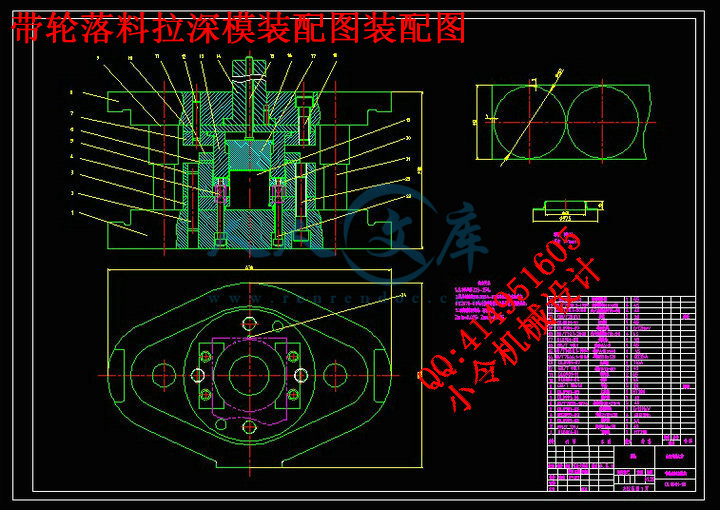
第一套带轮落料拉深模[12张]
第三套模具图[9张]
第二套模具图[9张]
第五套模具图[12张]
第四套模具图[9张]
设计参考资料
DAILUNTU.prt
压缩包内文档预览:(预览前20页/共43页)
预览图 预览图 预览图 预览图 预览图 预览图 预览图 预览图 预览图 预览图 预览图 预览图 预览图 预览图 预览图 预览图 预览图 预览图 预览图 预览图
编号:443051    类型:共享资源    大小:11.68MB    格式:RAR    上传时间:2015-06-22 上传人:好资料QQ****51605 IP属地:江苏
45
积分
关 键 词:
冲压 工艺 模具设计 全套 cad 图纸 毕业 答辩 论文 模具
资源描述:

目  录


摘 要··································································Ⅲ

ABSTRACT····························································Ⅳ

1 前 言

1.1 选题背景·····························································1

1.2课题设计思路·························································1

1.3设计过程中的难点·····················································2

2 工艺分析及计算

2.1工件的基本信息分析···················································3

2.2工艺分析·····························································3

2.2.1工序计算 ·························································4

2.2.2计算毛坯直径······················································5

2.2.3工艺方案的确定·····················································7

2.2.4排样及搭边·························································8

2.3工艺计算·····························································9

2.3.1工艺力的计算及压力机的选择········································9

2.3.2主要工作部分尺寸计算··············································12

3模具设计

3.1落料拉深复合模的设计················································15

3.1.1落料拉深复合模结构设计············································15

3.1.2落料拉深复合模主要零件设计········································16

3.2冲孔模设计··························································19

3.2.1冲孔模结构设计····················································19

3.2.2冲孔模主要零件设计················································20

3.3翻边模设计··························································22

3.3.1翻边模结构设计····················································22

3.3.2翻边模主要零件设计················································22

3.4切边整形复合模的设计················································24

3.4.1切边整形复合模结构设计············································24

3.4.2切边整形复合模主要零件设计········································25

3.5扩口压平复合模的设计················································27

3.5.1扩口压平复合模结构设计············································27

3.5.2扩口压平复合模主要零件设计········································27

4 结 论································································31

谢 辞··································································32

参考文献·······························································33


摘 要


本文是对拉深件进行工艺分析及模具设计。该工件是一个圆筒形拉深件,另外该工件的底部带有通孔,需进行冲孔翻边,虽然形状不太复杂但肯定不能一次成形。通过对零件各部分进行计算分析后才能最终确定加工工序。工件整个成形过程所涉及的工序有:落料、拉深、冲孔、翻边等四步。通过计算分析得翻边能一次成形,所以不需进行预拉深,而计算可知拉深可一次成形,所以确定最终工艺方案为:落料与拉深复合,冲孔、翻边复合。在确定工艺方案的基础上对主要模具进行设计,分析工件成型过程,设计模具的结构并画出模具装配图及零件图。在本次设计中主要对落料拉深复合模以及冲孔、翻边模进行设计。

关键词:拉深;落料拉深复合模;


ABSTRACT

The thesis is focus on the process analysis and mold design of the drawing.The workpiece we design is a cylinder-shaped drawing parts,which has a hole at the bottom.The workpiece should be punched and flanged.Although the shape is not very complex,it couldn’t be shaped by one step.We can determine the processing by analyzing the parts of the workpiece.The process include several steps:blanking,drawing,punching and flanging.By analysis,we know that the flanging can be finished by one step.There should not be a pre-drawing.However,the drawing can be achieved easily.Therefore,the final process is compounding the blanking with the drawing, the punching die and flanging die.Besides,we should design the main die,analyse the process,design the structure of the die and draw the assembly and workpiece picutures.In this graduation project,we mainly design the blanking drawing die, the punching die and flanging die.

Key words:  drawing die; blanking drawing compound die;


1前 言

1.1选题背景

带轮是带传动机构中重要的零件之一。它是一种用途十分广泛、年需求量很大的机械传动零件。

随着机械工业特别是汽车制造业的发展,节约原材料,降低能耗,提高整机的质量是普遍关注的大问题。因此,对作为机械传动零件的带轮如何优化设计,改革加工方法,对促进机械工业的发展具有特别重要的意义。对于发达的现代工业来说,笨重的铸铁带轮已较难适应现代工业化发展的需求。为此人们一直寻求一种新的替代品,进而突破传统工艺。

采用钢板冲压制作的皮带轮在这种时代背景下应运而生,采用钢板制作的皮带轮是一种轻型结构的带轮(通称钣制带轮)。冲压皮带轮作为皮带轮的一种新型的结构型式,以其精度高、重量轻、节能、节材、动平衡好、生产效率高,无环境污染等特点,己被汽车工业广泛应用,铸铁等型式的传统皮带轮将会逐渐减少使用,产生了良好的社会效益和经济效益。

同其他制造带轮的工艺方法相比,冲压带轮的有着巨大的优势:

(1)在具有足够刚度的条件下,冲压皮带轮重量轻,比铸铁带轮轻3/4以上。

(2)材料密度和壁厚均匀。因其是整体结构,成形工艺合理,尺寸精度高(即槽面径向跳动量一般在0.1一0. 2 ),动平衡性好,惯量小。

(3)同胀压法相比,所用工具和模具的费用低(为胀压模具费的1/5),而且强度高,寿命长,同时这种冲压成形的皮带轮具有可通用性,在工序周转和运输过程中的损坏率低。

(4)节能、节料、低成本。冲工艺能耗低,优于铸铁带轮的铸造与退火等能耗工序,节约能源材料在50%以上,效率高,每分钟可加工数件。

(5)无环境污染。工人劳动条件好,劳动强度低。

1.2课题设计思路

本设计为一多工序生产的筒形翻边件,该零件为一阶梯圆筒形拉深件,其形状虽然简单但成形工序较多,且产品批量较大,不宜采用单一工序生产,而用级进模结构太复杂,所以尽量采用复合模。

设计模具前首先通过计算确定方案的可行性,对工件进行工艺分析,计算毛坯寸,进而确定工艺方案,进行模具设计。

通过分析此工件,可以发现虽然其结构简单,但是所需的工序较多,有落料、拉深、冲孔、翻边、扩口、压平六个工序,因此如何确定工序顺序及各工序的复合成为此课题的关键。

1.3设计过程中的难点

本设计为一多工序生产的零件,筒形拉深成形时, 采用一次或多次成形工艺方法,同时要考虑到翻边能否一次完成,保证零件能够通过制定的工序生产出来。在该工艺过程中, 考虑材料在各个变形方向的成形极限, 从而预留足够的坯料。考虑工艺可行性与零件性能,选择较合理的工艺顺序是本次设计的一个难点,分析各个工序对材料性能以及零件精度的影响。再就是在扩口翻边工序进行时对模具的设计要求较高,需要用到斜楔滑块机构,必须保证模具设计的可行性,这是另一个难点。


内容简介:
本科毕业设计外文文献及译文文献、资料题目:Scale up and application of equal-channel angular extrusion for the electronics and aerospace industries文献、资料来源:材料科学与工程杂志文献、资料发表(出版)日期:2007.12院 (部): 材料科学与工程学院专 业: 材料成型及控制工程班 级: 成型054姓 名: 李瑜学 号: 2005101265指导教师: 任国成翻译日期: 2009.6.15山东建筑大学毕业设计外文文献及译文中文译文等通道转角挤压工艺在电子和航空航天行业的推广和应用摘要:促进等通道转角挤压发展以及在实验室的探索阶段取得进展,等径角挤压在这两个领域是至关重要的:(一)模具设计、处理设计和规模扩大(工具/加工设计与推广);(二)发展新亚微米晶产品。这两个目标在霍尼韦尔公司得到了实现。第一种情况是利用等径角挤压在电子工业从单相合金生产溅射靶材成功的商业化。在实际中的应用(毛坯尺寸)明显多于那些文献报道。其他的重合金铝材料在航空航天领域应用的描述则是以增加拉伸强度、高周疲劳和韧性为目的。在这些合金中,更好的了解塑性变形和降水机制之间的相互作用可达到最佳的性能。2007年埃尔塞维尔B.诉保留所有权利1 导言过去10年,剧烈塑性变形(SPD)技术已成为热切研究的焦点,因为他们可以用尺寸在50到500纳米之间亚微米晶粒研究生产金属材料 。一个有前途的剧烈塑性变形(SPD)方法是等通道转角挤压( 等径角挤压 )工艺。它可以通过简单的剪切引起的剧烈塑性变形产生出大量的亚微米晶粒材料。到目前为止,研究已在亚微米晶材料的的表征纹理、结构和力学性能,以及等径角挤压影响的主要参数和畸变退火方面取得稳步进展。然而,尽管有丰富的文献资料,但在工程和商业化方面的问题直到最近才讨论,且很少有实际应用的报道。绝大多数研究者继续使用小长圆筒形或方形坯料。 已经有一些扩大规模的钢坯的尝试,但还没有成功的商业化的报告。本文综述了,霍尼韦尔公司在模具设计,推广和商业化等径角挤压平板钢坯进行获得的成果。选定的例子表明,该技术可以以一个或多个下列方式进入市场: (一) 提供全面降低成本以针对标准制造或设计,(二)提供优异的产品性能,(三)答复一个未得到满足的需求。第一个涉及等径角挤压产品的例子是使用微米与亚微米尺寸晶粒的高纯度铝、铜和钛制造用于制造逻辑和存储元件溅射靶材。另外两个例子是关于中等和重合金铝材料在航空航天和运输领域的应用。特别注意的是影响等径角挤压的结构和性能的单相铜和铝,尤其是铝在合金成分的增加从一个非常低的水平(如溅射靶材)到一个更高的水(如在商业合金为航空航天)。有人认为,新的机制和随着新的塑性变形之间的相互作用和形变热处理时的相变使合金水平的提高,更多合金应用机会将出现。2规模和工艺设计霍尼韦尔公司的重点是,从历史上看, 等径角挤压平板产品,这是第一次介绍了编号。 38 在这种情况下(图1 ),一个典型的坯料形状的特点是厚度为a,宽度为b和长度c,b c。通常情况下,尺寸C和B是平等的,允许使用相同的工具进行多道次处理(在 90 之间轮换通过)。加工特性之一是等径角挤压平板和长期钢坯相似。不过,通常用于平板钢坯的轴允许 90钢坯轮换垂直挤压(图1 中z轴),鉴于长期的产品,它是平行的挤压轴。在规模增长方面,有两个因素在起作用:(i)模具设计,及( ii )优化等径角挤压变形模式。2.1 .模具设计 从生产角度看,主要的驱动程序工具设计包括安全,成本和生产力。2.1.1 .安全性和成本如果使用常规低成本工具钢,最大的问题是冲床潜在的断裂/屈曲。对于给定的材料,冲床压力p1必须大大低于冲压材料的屈服强度。冲压力为其中p是在出口的第一通道的压力,K为材料剪切流动应力m是塑料的摩擦系数F是该地区固定死墙壁A是钢坯横截面积对于该工具本身,最大的冲床压力p1和通道壁的n行动结束时的入口通道。同样地显示在 30 ,低摩擦情况(m 0.25 )因此,最好的减少模具/冲压压力的办法是: (一)限制比例的c / a6-10(二)减少两个通道的摩擦。有两个相应的策略:选择有效的润滑剂和使通道壁可动。这是利用单位平板等径角挤压钢坯相对长期的钢坯的一个明显优势,从设备和设计是可移动的墙壁通道沿线theentrance不需要平板产品。这是因为平板产品中ab,而长期产品中a = b。因此P1和n在平板产品中是较小的,公式( 2 )和公式( 3 )可近似化简为建议在平板和条状的产品中增加一个可移动底部出口通道,因为底部是润滑油原子的退出通道。2.1.2 .生产率影响生产率的两个重要的因素是加工速度和钢坯弹射。作为具有相当的韧性的材料,加工速度不是一个限制因素,它可以足够高( 5-10毫米/秒)。钢坯弹射具有更为复杂的问题,特别是对长条圆柱形坯料。在平板钢坯中,在可移动的墙底部退出渠道安装的额外液压缸提供了一个有效和简单的解决办法。2.2 优化等径角挤压有两个层次的单一优化和多道优化 等径角挤压。2.2.1.单程优化某种程度的简单剪切变形应尽可能高的一种有效的完善的组织。这主要取决于摩擦条件和几何渠道,有两个临界参数改变几何渠道:两个通道之间的夹角2及通道相交的形状。通常情况下,通常情况下,渠道都以尖角(没有半径)或圆角的交叉。滑移线解决方案和有限元模型揭示在摩擦和(或)圆角渠道的情况下存在扇形变形区。在这种情况下,简单剪切是重新分配沿着三个不同的方向。而且即使是无摩擦的条件和尖角弯道,290时死金属区存在于通道的角落。因此,工具角2 = 90时,急转弯道和附近摩擦条件是实现沿=2一个方向简单有效剪切的最佳的条件。最重要的问题是同时采取行动消除有高压缩压力的沿底部墙壁和密集支路的摩擦。随着底部墙壁的移动, 滑移线分析表明扇形角度可以减小。由于先进的模具设计和润滑油条件,霍尼韦尔模具运作良好。2.2.2 .多道处理多道处理的两个主要参数是变形路线(每次变形后一序列方坯的轮换,)和变形总数的积累(积累株),平板钢坯,定义的四个基本路线,A、B(或BA )、C和D(或BC)仍然是类似的长条钢坯除如前所述的旋转轴。 2.3 .规模扩大的努力基于上述考虑,霍尼韦尔公司开始了扩大等径角挤压规模的努力,在1997年建造的第一条模具生产线。今天,一些正常使用铝铜和纯钛大规模的钢坯模组使用1000和4000吨的压力机(见图2 ) 。其中大部分模具已在使用中,6年中每周工作。大众中最大的等径角挤压方坯是三十二点七公斤的Al合金,最近,110公斤的铜和铜合金也有了。作为比较,报告的最大等径角挤压加工铝坯模具有6.7千克重获得渠道角度105 而大众的用于研究的最典型的10毫米 10毫米 60mmAl钢坯是0.016千克。 关于企图扩大等径角挤压过程没有任何对铜的报告。重要的是, 等径角挤压对微观结构,质地和性能的影响已经在各种规模的工业领域得到验证并将在第2部分介绍。在作者看来,实际生产经验表明, 等径角挤压是可扩展的并将开创它的工业化新时代。3 等径角挤压的溅射靶材等径角挤压特别适用于高纯度材料由于晶粒细化是有效地增强强度,并保持良好的塑性(霍尔佩奇硬化)唯一可用机制,而其他硬化机制都是无效的(析出和硬化处理)或有损于延性(脱位硬化) 。对特定材料和晶体结构而言, 等径角挤压can也激活和控制质地的硬化。这种办法对掺杂或低合金钢材料,如在高纯度的铜,钛和Al 材料或不使用微量元素和低合金中使用制造溅射靶材仍然有效。在本节中,我们使用电极工业缩写, 6N和5N5的纯度分别99.9999 和99.9995 。3.1 等径角挤压后靶材的微观结构高纯度材料的多道等径角挤压结果存在以下几个主要影响:(一)形成较好(通常是小于20微米)微观结构取决于开始的晶粒尺寸; (二)加强结构均匀性; (三)纹理的控制是通过一些通行证,路线和后处理热处理来实现的 39 ;( 四 )在等径角挤压之前通过固溶处理来消除大型阶段和沉淀。晶粒尺寸,均匀性和缺乏大型粒子对溅射性能力影响最大。选择特定结构的关键因素是在靶材制造或使用过程中的热稳定性。下面是一些例子:(一) 对低熔点高纯度材料而言,亚微米晶结构通常没有稳定的高功率溅射。但是,在等径角挤压之后仍然能得到结构很好和均匀的,而且微米晶粒尺寸较普通结构锻造或轧制后小3到5倍。这对等径角挤压的应用而言是一个非常有趣的领域,由于把重点放在亚微晶材料,因此很少在文献中强调,。另一个例子 36,37 是一种 5-10微米结构(图3a )在纯度为99.9999 ( 6N )的铜经过等径角挤压静态再结晶( 225 , 1小时)后 与普通处理典型的50米晶粒尺寸的对比。该EBSD分析表明, 高角度边界占主导位置(图3B )。 60 也界证明存在大量的孪晶组织。另一个例子(图4和5 ) ,高纯度99.9995 ( 5N5 ) Al经由等径角挤压后的平均粒径约为60-70微米,而而标准处理则是200-300微米。在这情况下,经过等径角挤压直接观察室温下的完全动态再结晶。正如文献 41,42 所述,不仅是应变的积累,而且简单剪切变形模式也是很重要。在特定的情况下,在如图4所给的应力水平下对结构的改良来说简单的剪切是最有效的模式结构。 例如相同的结构,发现5N5铝经过两次等径角挤压后(积累应变2.3 )和轧后减少99 (累积应变4.8 )。这种结构有一个突出特点即热稳定性增强。起作用的因素可能是各向同性的形态,孪晶晶界的低流动性, 结构均匀性及附近纹理的随机性(见图3 )。图5经过等径角挤压和一般工艺处理5N5铝, 6N 铜 37 和铜合金之间的晶粒尺寸演变随退火时间变化的比较。例如,对于等径角挤压 6N铜而言,完全静态再结晶发生在225 C的、退火1 小时和产生了尺寸约为5-8微米的均匀晶粒,而在300 额外的退火1小时后晶粒只是稍微长大至15微米,结构仍然均匀。 相比之下,相同晶粒尺寸6N铜经过标准工艺处理( 85 滚动)后在经过225 , 1 h和300 退火 1小时后,分别晶粒尺寸由35升至65米。(二) 对高纯度铝,铜而言,添加微量元素(这里定义为元素含量最多为百万分之2000)是一个进一步完善等径角挤压晶粒尺寸和/或通过提高晶粒度和亚显微结构的热稳定性同时来提高等径角挤压 温度极为有效的技术。一个显着的例子是5N5铝掺杂百万分之20-30硅含量。超细颗粒的大小由 60微米减少至25微米,远远小于类似的应变水平(图4 )作为推出结构之后的尺寸。简单的剪切变形模式等径角挤压和非单调D类加载路径被认为是等径角挤压和推出结构的晶粒尺寸之间存在显着差异的最主要的因素 41,42 。图。 6显示了元素性质和掺杂数量对亚微米颗粒6N铜按照路线D经过6次等径角挤压后的温度静态再结晶巨大的影响。可以得到一个近乎对数的曲线。特别是银,锡,钛影响如此大以致有添加微量的元素有足够的水平产生稳定溅射的亚微米颗粒的结构。(三) 在含有足够数量的微量元素或合金的纯Al和Cu的的组成部分,在现实应用中亚微晶结构稳定溅射是我们追求的靶材。例如一个Al0.5Cu合金亚微米晶结构经过等径角挤压处理,如图7所示 36,37 。透射电子显微镜( TEM )展示了一个均匀等轴尺寸0.3-0.5微米的微米晶粒(图7 ) 这对当于常规过程100个因素的比较。存在着非常细的分散(小于50纳米)的第二阶段物质。3.2 溅射性能等径角挤压结果展示了溅射性能优越(具体细节参考文献36,37 ) ,其中包括: (一)减少电弧; (二)低水平的粒子和晶圆上缺陷; (三) 改进薄膜厚度均匀性和薄膜的统一性; (四)由于存在较好束直的亚微米颗粒的结构进而进一步提高了覆盖。3.3 力学性能和指标的设计图8显示数据是6N铜,含有微量元素的6N Cu,6N Cu,5N5 Al0.5Cu 和 4N5 Ni在室温下经过等径角挤压处理后的屈服强度(YS)和极限抗拉强度强度(UTS)。经过等径角挤压处理后的屈服强度(YS)和极限抗拉强度强度(UTS)要比常规处理分别高4至10倍和2至3倍。这种效果在屈服强度上最显著,屈服强度是材料应用的一个重要指标,因为它表示承受永久塑性变形的能力,并可能使工件在溅射靶时发生弯曲。由图8可知在6NCu这一组,经过等径角挤压后微量元素有一个明显的强化效果,。拉伸伸长率仍然很高: 较亚微晶 Al0.5Cu高出20 ,较亚微晶6N铜高出35-40。高强度的纯亚微米晶材料允许使用单片设计,整个靶材作为一个单块(图9 ) 。较常规工艺的指标而言这是一个独特的设计,其中经过靶材材料粘结或焊接到底板材料制成类似Al 6061 或 CuCr这样高强度材料。单片设计主要优点如下:相比扩散粘结的设计靶材寿命增加了50 ,因为溅射不再局限于扩散结合线 36,37 。直接结果就是增加吞吐量(一些经过处理的晶圆每个指标),其他组成部分的寿命和减少停机时间。通过降低成本,多而高风险的扩散焊作业来简化制造过程。归因于等径角挤压可以获得如常规手段(滚动,绘图)一样的高塑性变形的产品。 等径角挤压 Al和Cu靶材的最近事态发展的是空心阴极磁控( HCM )的靶材。这些靶材成形需要经过复杂的等径角挤压工艺形成最终直径约393.7毫米,高度381毫米和厚度12.7-25.4毫米的杯形状。4 等径角挤压铝合金在航空航天和运输上的应用随着加入合金成分的增加,二次相(无论可溶性或不溶性)得数量也随之增加,因此便产生了两个其他可能提高强度的机制: 固熔案和沉淀硬化。等径角挤压热处理对组织和性能额影响变得更加多样化和更难以预测。对于非热处理合金晶粒细化在等径角挤压仍然是提高强度的主要机制 2,12 。对可热处理合金而言会产生更有趣的实例。对于一个中等水平的合金,沉淀硬化同晶粒细化一样有效,目标就是优化处理来结合这两种效果 13,20-24 。下文所述的一个例子是等径角挤压铝2618合金,主要用于航空及运输行业的涡轮增压器组件。对重合金化而言,通过等径角挤压细化组织来提高材料强度相对于其他硬化机制是次要的。然而,经过等径角挤压处理的喷雾铸铝合金的起落架组成部分的韧性可以大大提高 25-29 。4.1 等径角挤压铝2618的涡轮增压器组件4.1.1 加工 在进行等径角挤压前将物质状态分三组进行了研究:(一)在529 固溶,24 h后,立即用水淬火使所有溶解相溶解。(二)在526 ,固溶20小时之后,经沸水淬火然后在200时 , 空冷20小时。这个扩建条件提供了一个平衡固溶矩阵与0.05-0.1米CuMgAl2沉淀和HB硬度为115。(三)在529 , 固溶24小时之后,水淬和在385 ,空气中过度时效4小时产生大量沉淀物,降低强度和HB硬度为47.5。 在这组中,进行等径角挤压加强效果的评估。在所有情况下,按照如第3节 中所描述的D类工艺(旋转90 ),模具温度在150至200 范围内分别进行一,二,四及六次等径角挤压。同时对后等径角挤压的等时退火也进行了研究。4.1.2 。拉伸性能表1显示了等径角挤压对硬度,屈服强度,抗拉强度和伸长率的影响。主要成果:单独进行等径角挤压的晶粒细化(案例三)有效的增加强度比超峰时效约少25 。但是,硬度, 屈服强度和抗拉强度仍分别高于氧条件约2 ,4和2倍。 与传统的T6条件相比,经过超峰时效的等径角挤压样本(案例二)造成只是稍微提高了拉伸性能。图。实验组1,屈服得到明显改善。经过第一遍工艺,相比T6条件屈服强度,抗拉强度和伸长率分别提高了40 , 25 和30 。经过两次工艺加工后,屈服强度和抗拉强度在类似的延性方面又分别增加了是50 和35 。经过四道工艺,强度增加较工艺次数少的时候少,与T6状态相比约减少了 10 ,。长期进行低于超峰时效温度退火进一步提高强度和略有改善延性。在第一次工艺后实验参数为退火温度150 , 10 h,列于表1 。4.1.3 。微结构和强化机制图10显示的是经过第一和第四次工艺后的TEM显微图像,在第一次工艺后,结构由复杂脱位配置(图10b)和0.10.3微米二次晶粒组成(图10a)。极精细得约1微米的G.P区(图10b),或者呈一致的球形或着部分连贯,时刻存在于整个样本中。经过四年道工序后, 基体之间的界限变得模糊。平均晶粒尺寸为0.1微米如图10C所示,其附近存在大量不溶性的沉淀物。位错常常存在于边界处,以少量位错群的形式存在。同时可以看到尺寸较大的连贯的G.P区。对实验组2,3而言,G.P区消失了,取而代之的是粗沉淀(实验组2小于0.25微米和实验组3超过5微米)。实验组1的加固现象可以有以下两方面解释 20-24 :(一)通过增加位错,晶粒或边界的切应力来使其移动 ;(二)高密度的G.P区在热等径角挤压的动态和在彼此等径角挤压过程预热的静态。这种占主导地位的机制是相互作用的高度密集的G.P区和位错或细胞间的最佳组合。这种最佳机制强于仅用等径角挤压来细化晶粒(实验组3),单独使用常规工艺细化晶粒(T6)和等径角挤压后沉淀硬化(实验组2)。对于低工艺次数而言这是最有效的方法。而高次数的工艺,重排和恢复的位错,增大.P区和沉淀物受剪切力能有助于减少加强效果。4.1.4疲劳性能涡轮增压器组件的关键要求是其疲劳性能,因为其持续工作在压力、流量和速度都大的环境下,同时发动机的排量有严格的控制,还有就是要考虑到经济因素。在高周疲劳下,根据TMP的条件对铝2618合金试样进行了CAE处理。在控制轴向载荷、温度在25到150之间、应力比R=0和R=-1、频率59Hz以及正弦波形的条件下进行了测试。通过对铸造354/C355的标准铝合金涡轮增压器和锻压2618T6铝合金涡轮增压器进行比较,据Sines当量应力44提出的论证的多轴高疲劳效应,做了进一步的分析。实验结果表明对于两个压力比值,抗疲劳性能都有了明显的提高。图11给出了在R=0时的数据比较。在10到80周次时,疲劳寿命的增加主要取决于Sines压力水平。原始数据显示, 其最多可提高230倍。有趣的是,在如今应用最为广泛的140-200MPa水平的Sines当量应力中,铝2618合金的ECAE应用情况可类似的应用于钛合金铸造中。4.2ECAE应用于重铝合金压铸的飞机起落架部件。4.2.1实验起始原料是压铸合金组成为6.7 的锌,3 的镍 , 3 的锰,2.6 的镁 , 0.7 的铜等元素的Al7xxx合金。该合金已应用于常规飞机的起落架部分,但是它的韧性和拉伸强度还不符合规范。铸造后ECAE直接采用了在275时线路D的一、四、八及十六步进行操作。在ECAE之后,485固溶一小时,温水中淬火,并且是在T7条件下进行这些操作。其显微结构用扫描电镜(SEM)和光学显微镜进行观察。而固溶物的尺寸则由扫描电镜和破坏性液体粒子计数(LPC)来测定。用光滑试样和缺口试样来同时评价其YS、UTS、韧性及NYR。42.2实验结果原始铸态组织主要有两种大型沉淀的类型,它们有5-60的稀缺圆形氧化物以及0.5-20的伴有锌、锰和镁的镍富集阶段。它们形成了一个统一的网络结构(如图12a示)。同时存在着0.10.2的非常细的弥散物。Fig. 12. Optical microscopy of second phase precipitates in a spray-cast Al 7xxx modified alloy in the (a) as cast condition, (b) after one ECAE pass, and (c) aftereight ECAE passes.图12b和c给出了由ECAE作为数字功能时,固溶物所起到的作用。表2显示了相应固溶形态的其中之一,即四个和八个的过程。在第一个步骤之后会看到断裂和拉伸的出现。在四和八过程之后,大于10和3m的固溶物中有个别的未检出 ,但是相对比例最小的固溶物却逐渐增多。也许,固溶强化机制是在断裂和沿成功剪切面和在ECAE通过路线D激活的方向上,断裂和连续均一不断的完善了固溶强化机制。表3总结了对于铸态组织条件下以及经过在T7条件下ECAE的八和十六步骤后固溶强化机制的可测量性。切口屈服率相对于初始态提高了,这是因为在八和十六步骤后1.8和2.45的因素。这种效应伴随着小但是总深长率却不断增加的情况出现。除原因尚不明确的16路径硬度减少5%之外,其强度和硬度基本保持稳定。ECAE应变的较高水平带来的高积蓄能量是可能会导致固溶动力和沉淀速度的增加的。提高韧性时占主导地位的机制是晶粒细化以及特殊非可溶性第二相和氧化物的初始微裂变致使得均一化。这种效应可能会得到更强大的合金及高合金浓度。总体而言,本研究及其他研究 25-30 表明ECAE在晶粒细化机制之外会产生独特的性能。TEM的运用可以更好的了解这些现象。5结 论(1)ECAE平错齿饰的按比例放大已在大量的铝、铜以及钛的合金中得到了应用。重量的处理明显高与参考文献中所写到的。到目前为止,在采用基于过程理论了解的机理时,由简单剪切而形成的晶粒细化机制被验证是可操作并且是最为理想的。(2)ECAE的商业化已被应用,并且通过亚微晶和少量微晶这两种不同尺寸类型的微晶开发了新型的铝铜合金的溅射靶材。有人认为,在对提高诸如高纯度,掺杂,低合金钢或不耐热合金钢的力学性能时具有明显优势,其原因是晶粒细化机制是其唯一强化机制。(3)随着合金成分数量的增加,由于激烈变形和热处理的相互作用,新机理和结构的出现是有可能的。然后才能把各种强化机理加以合并,并且(或者)提高其疲劳或韧性这样的具体的属性。这样有利机制除细化晶粒外,还有提纯、沉淀阶段的匀质处理以及第二相变。谢词作者祝C.C.Kouch 博士70岁生日快乐。我们感谢他的原因是他是材料科学和工程A的作者之一,同时感谢M.Payton 和B.Willett的协助,以及D.Mathur和B.Daniels的大力支持,还有S.Chadda的高度赞赏。参考文献:1 C.C. Koch, Rev. Adv. Mater. Sci. 5 (2003) 9199.2 R.Z. Valiev, R.K. Islamgaliev, I.V. Alexandrov, Prog. Mater. Sci. 45 (2000)103.3 V.M. Segal, V.I. Reznikov, A.E. Drobyshevky, V.I. Kopylov, Russ. Metall.1 (1981) 971974.4 M. Furukawa, Z. Horita, M. Nemoto, R.Z. Valiev, T.G. Langdon, ActaMater. 44 (1996) 46194629.5 M.V. Markushev, C.C. Bampton, M.Yu.Murashkin, D.A. Hardwick, Mater.Sci. Eng. A 234236 (1997) 927.6 Y. Iwahashi, M. Furukawa, Z. Horita, M. Nemoto, T.G. Langdon, Metall.Mater. Trans. A 29 (1998) 2245.7 O.V. Mishin, G. Gottstein, Phil. Mag. A 78 (1998) 373388.8 J.J. Beyerlein, R.A. Lebensohn, C.N. Tome, Mater. Sci. Eng. A 345 (2003)122138.9 S.D. Terhune, D.L. Swisher, K. Oh-Ishi, Z. Horita, T.G. Langdon, T.R.McNelley, Metall. Mater. Trans. A 33 (2002) 21732184.10 F.J. Humphreys, P.B. Prangnell, J.R. Bowen, A. Gholinia, C. Harris, Phil.Trans. Roy. Soc. Lond., Ser. A 7 (1999) 16631680.11 V.M. Segal, Mater. Sci. Eng. A 197 (1995) 157164.12 S. Ferrasse, V.M. Segal, K.T. Hartwig, R.E. Goforth, Metall. Mater. Trans.A 28 (1997) 1047.13 S. Ferrasse, V.M. Segal, K.T. Hartwig, R.E. Goforth, J. Mater. Res. 12(1997) 1253.14 A.Y. Vinogradov, V.V. Stolyarov, S. Hashimoto, R.Z. Valiev, Mater. Sci.Eng. A 318 (2001) 163173.15 S.R. Agnew, J.R. Weertman, Mater. Sci. Eng. A 244 (1998) 45153.16 S.R. Agnew, A.Y. Vinogradov, S. Hashimoto, J.R. Weertman, J. Electron.Mater. 28 (1999) 10381044.17 H.W. Hoppel, R.Z. Valiev, Z. Metallkd. 93 (2002) 641648.18 V.M. Segal, V.I. Reznikov, V.I. Kopylov, D.A. Pavlik, V.F. Malyshev, ProcessyPlasticheskogo Structyroob Razovania Metallov, Sci. Eng. Minsk(1994) (in Russian).19 R.Y. Lapovok, Mater. Sci. Forum 503504 (2006) 3744.20 R.Y. Lapovok, C. Loader, F.H. Della Torre, S.L. Semiatin, Mater. Sci. Eng.A 425 (2006) 3646.21 A. Goloborodko, O. Sitdikov, R. Kaibyshev, H. Miura, T. Sakai, Mater. Sci.Eng. A 381 (2004) 121128.22 J.K. Kim, H.K. Kim, J.W. Park, W.J. Kim, Scripta Mater. 53 (2005)12071211.23 Y.H. Zhao, X.Z. Liao, Y.T. Zhu, R.Z. Valiev, Mater. J. Res. 20 (2005)288291.24 Y.H. Zhao, X.Z. Liao, Z. Jin, R.Z. Valiev, Y.T. Zhu, Acta Mater. 52 (2004)45894599.25 A. Ma, K. Suzuki, N. Saito, Y. Nishida, M. Takagi, I. Shigematsu, H. Iwata,Mater. Sci. Eng. A 399 (2005) 181189.26 A. Ma, K. Suzuki, Y. Nishida, N. Saito, I. Shigematsu, M. Takagi, H. Iwata,A. Watazu, T. Imura, Acta Mater. 53 (2005) 211220.27 Z.G. Zhang, Y. Watanabe, I. Kim, Mater. Sci. Technol. 21 (2005)708;C. Xu, M. Furukawa, Z. Horita, T.G. Langdon, Acta Mater. 53 (2005)749758.28 I. Sabirov, O. Kolednik, R.Z. Valiev, R. Pippan, Acta Mater. 53 (2005)49194930.29 Y. Huang, C. Xu, S. Lee, M. Furukawa, Z. Horita, T.G. Langdon, UltrafineGrained Materials II, The Minerals, Metals and Materials Society,Warrendale,PA, 2002, p. 173;Y.T. Zhu, T.G. Langdon, JOM (2004) 5658.30 V.M. Segal, Mater. Sci. Eng. A 386 (2004) 269276.31 T.C. Lowe, JOM (April) (2006) 2832.32 R.Z. Valiev, V.V. Stolyarov, H.J. Rack, T.C. Lowe, Adv. Mater. Process(2003) 33.33 R. Srinivasan, P. Chauduri, Mater. Sci. Forum 426432 (2003) 267272.34 P.K. Chaudhury, B. Cherukini, R. Srinivasan, Mater. Sci. Eng. A 410411(2005) 316318.35 R. Srinivasan, B. Cherukini, P.K. Chaudhury, Mat. Sci. Forum 503504(2006) 67272.36 S. Ferrasse, V.N. Segal, F. Alford, S. Strothers, J. Kardokus, S. Grabmeier,J. Evans, in: B.S. Altan (Ed.), Severe Plastic Deformation: Toward BulkProduction of Nanocrystalline Materials, Nova Science Publisher, NewYork, USA, 2006, pp. 585601.37 S. Ferrasse, F. Alford, S. Grabmeier, S. Strothers, J. Evans, B. Daniels, A.Duvel, R. Zedlitz, Semiconduct. Manuf. 4 (2003) 7692.38 V.M. Segal, US Patent 5,850,755 (1998).39 S. Ferrasse, V.M. Segal, S.R. Kalidindi, F. Alford, Mater. Sci. Eng. A 368(2004).40 M. Furukawa, Z. Horita, T.G. Langdon, Mater. Sci. Eng. A 332 (2002)97109.41 V.M. Segal, Mater. Sci. Eng. A 345 (2003) 3646.42 V.M. Segal, Mater. Sci. Eng. A 338 (2002) 331344.43 R. Srinivasan, Scripta Mater. 44 (2001) 91.44 A. Faterini, R.I. Stephens, H.O. Fuchs, Metal Fatigue in Engineering,Wiley,USA, 2001, p. 325.18Materials Science and Engineering A 493 (2008) 130140Scale up and application of equal-channel angular extrusionfor the electronics and aerospace industriesStephane Ferrassea, V.M. Segalb, Frank Alforda,Janine Kardokusa, Susan StrothersaaHoneywell Electronic Materials, 15128 E. Euclid Avenue, Spokane, WA 99216, USAbEPM, 11228 Lemen Rd-Suite A, Whitmore Lake, MI 48198, USAReceived 9 February 2007; received in revised form 12 April 2007; accepted 25 April 2007AbstractTwo areas are critical to promote equal-channel angular extrusion beyond the stage of a laboratory curiosity: (i) tool/processing design and scaleup;(ii)developmentofnewsubmicrometer-grainedproducts.BothgoalsarepursuedatHoneywell.Thefirstcaseisthesuccessfulcommercializationof ECAE for the production of sputtering targets from single phase alloys in the electronic industry. Blank dimensions are significantly larger thanthose reported in the literature. Other described applications are targeted to the increase of tensile strength, high-cycle fatigue and toughness inmedium-to-heavily alloyed Al materials used in aerospace. In these alloys, the optimal properties can be reached with better understanding of theinterplay between plastic deformation and precipitation mechanisms. 2007 Elsevier B.V. All rights reserved.Keywords: ECAE; Submicrocrystalline materials; Flat products; Sputtering; Fatigue; Toughness1. IntroductionFor the past 10 years, severe plastic deformation (SPD) tech-niques have been the focus of intense research because theycan produce metallic materials with submicrometer grain sizesranging from 50 to 500nm 1,2. One promising SPD methodis equal-channel angular extrusion (ECAE) 3. It can pro-duce bulk pieces of submicrocrystalline materials induced byintense plastic straining by simple shear. Till now, researchhas made steady progress on the characterization of the tex-ture,structureandmechanicalpropertiesofsubmicrocrystallinematerials and the effect of main ECAE parameters and post-deformation annealing 429. However, despite the abundantliterature, problems of engineering and commercialization werediscussed only recently 3032 and very few practical appli-cations are reported. The overwhelming majority of researcherscontinue to work with small long cylindrical or square billets.A few attempts to scale up the billet size are known 3235 butthere is no report of successful commercialization.This paper reviews the efforts in die design, scale up andcommercialization of ECAE for flat billets conducted at Honey-Corresponding author. Tel.: +1 509 2522118; fax: +1 509 2528743.E-mail address: Stephane.Ferrasse (S. Ferrasse).well 36,37. Selected examples show that this technology canpenetrate a market in one or more of the following ways: (i)provide an overall cost reduction versus the standard manufac-turing or design, (ii) provide superior product performance and(iii)answeranunmetneed.OneexampleinvolvesthefirstECAEproductswithsubmicrometerormicrometergrainsizesforhighpurity Al, Cu and Ti sputtering targets used in the fabricationof logic and memory components. Two other examples concernmedium and heavily alloyed Al materials used in aerospace andtransportation. Special attention is paid to the effects of ECAEon the structures and properties of single phase Cu and, espe-cially, Al when the amount of alloying composition increasesfrom a very low level (as in sputtering targets) to a higher level(as in commercial alloys for aerospace). It is argued that newmechanisms and, therefore, additional opportunities for appli-cations arise as the alloying level increases because of the newinterplay between plastic deformation and phase transformationduring a thermo-mechanical treatment.2. Process scale up and designHoneywells focus has been, historically, the ECAE of flatproducts, which was first introduced in Ref. 38. In that case(Fig. 1), a typical billet shape is characterized by thickness a,0921-5093/$ see front matter 2007 Elsevier B.V. All rights reserved.doi:10.1016/j.msea.2007.04.133李瑜S. Ferrasse et al. / Materials Science and Engineering A 493 (2008) 130140131width b and length c with c, b?a 30,3840. Usually, dimen-sions c and b are equal to allow the use of the same tool formulti-passprocessing(with90rotationbetweenpasses).Theprocessing characteristics of one pass ECAE for flat and longbilletsaresimilar.However,usually,forflatbillets,theaxisofthepermissible90billetrotationisperpendiculartotheextrusionaxis (axis Z in Fig. 1) whereas, for long products, it is parallel totheextrusionaxis.Duringscaleup,twoconsiderationscomeintoplay:(i)tooldesign,and(ii)optimizationofECAEdeformationmode.2.1. Tool designFrom a production perspective, the major drivers for tooldesign include safety, cost and productivity.2.1.1. Safety and costThe biggest issue is the potential breakage/buckling of thepunch if conventional low cost tool steels are used. For a givenmaterial, the punch pressure p1must be significantly less thanthe yield strength of the punch material. The punch pressure is30p12k=p2k+mF2A(1)wherepisthepressureattheexitoffirstchannel,kisthematerialshearflowstress,mistheplasticfrictioncoefficient,Fistheareaof stationary die walls and A is the billet cross-sectional area.For the tool itself, the maximum pressures on the punch p1and channel wall nact at the end of the entrance channel. Asshown in 30, for a low friction case (m0.25)p12k 1 +m(cb + ca)ba(2)n2km(cb + ca)ba(3)Therefore, the preferable ways for reducing die/punch pres-sures are (i) to limit the ratio c/a610 and (ii) to minimizefriction in both channels. Two corresponding strategies are thechoice of effective lubricants and movable channel walls. A sig-nificant advantage of flat ECAE billets versus long billets interms of equipment and design is that movable walls along theFig. 1. Principle of the ECAE technique for flat billets.entrancechannelarenotneededforflatproducts.Thisisbecausea?b for flat products whereas a=b for long products. There-fore p1and nare lower for flat products and formulae (2) and(3) can be approximately reduced top12k 1 +mca(4)n2kmca(5)A movable bottom wall at the exit channel is recommendedhowever for both flat and long products because lubricant isatomically removed along the bottom of exit channel.2.1.2. ProductivityThe two important factors are processing speed and billetejection. For reasonably ductile materials, the processing speedisnotalimitingfactorandmaybesufficientlyhigh(510mm/s).The billet ejection presents a more complex problem, especiallyfor long cylindrical billets. In the case of flat billets, a mov-able bottom wall of the exit channel operated by an additionalhydraulic cylinder provides an effective and simple solution.2.2. Optimization of ECAETherearetwolevelsofoptimizationforsingleandmulti-passECAE.2.2.1. Single passA level of simple shear straining should be as high as possi-ble for an effective refinement of microstructures 11. This ismostly controlled by the conditions of friction and the chan-nel geometry which has in turn two critical parameters: (i)the angle 2 between the two channels and (ii) the shape ofthe channel intersection. Usually, channels are performed withsharp (no radius) or round corner intersections. Slip line solu-tions 18,30,41 and finite element modeling 43 reveal theexistence of a fan-like deformation zone in cases of noticeablefrictionand/orroundcornerchannels.Insuchcases,simpleshearis redistributed along three different directions 41. Moreovereven for frictionless conditions and sharp corners, a dead metalzone exists at the channel corner for 2 90. Therefore, toolangle 2 =90, sharp corner channels and near frictionless con-ditions are the optimum characteristics to realize the effectivesimple shear of =2 along one direction. The most importantproblem is the elimination of the friction along the bottom walloftheoutletchannelwherehighcompressivepressureandinten-sive slip act simultaneously. With the movable bottom wall,the fan angle can be minimized as shown by slip line analy-sis 30,41. The Honeywell dies operate under those conditionsowing to advanced die design and lubricants.2.2.2. Multi-pass processingThe two major parameters are the deformation route (asequence of billet rotation after each pass) and the total numberof passes (accumulated strains). For flat billets, the definition ofthe four fundamental routes A, B (or BA), C and D (or Bc) 38132S. Ferrasse et al. / Materials Science and Engineering A 493 (2008) 130140Fig. 2. Production ECAE die with 4000tonnes press capacity.remains similar to long billets except for the axis of rotation asdescribed earlier.2.3. Scale-up effortsBased on the above considerations, Honeywell started thescale-up efforts of ECAE in 1997 with the construction of thefirst production die. Today, several large-scale die sets for a fewstandard billet sizes are in normal operation for Al, Cu and,occasionally, pure Ti using presses with 1000 and 4000tonnescapacity (Fig. 2). Most of these dies have been in use on aweekly basis for 6 years. The mass of the largest ECAE bil-let is 32.7kg for Al alloys 36 and, most recently, 110kg forCu and Cu alloys. As a comparison, the largest reported ECAEprocessed Al billet obtained with a die channel angle of 10534,35hasamassof6.7kgwhereasthemassofthemosttypical10mm10mm60mmAlbilletusedforresearchis0.016kg.Thereisnoreportofascale-upattemptoftheECAEprocessforCu.Importantly,theeffectsofECAEonmicrostructures,textureand properties have been verified at the various industrial scalesas will be shown in the Section 2. In the authors view, the expe-rience attained on the production floor demonstrates that ECAEis scalable and opens up the era of its industrialization.3. ECAE of sputtering targetsECAE is particularly interesting for high-purity materialsbecause grain refinement is the only available mechanism thateffectively enhances strength and retains good ductility (Hall-Petch hardening) whereas the other hardening mechanismsare either ineffective (precipitation and solution hardening) ordetrimental to ductility (dislocation hardening). For specificmaterialsandcrystalstructures,ECAEcanalsoactivateandcon-trol texture hardening. This approach remains valid for dopedor low-alloyed materials such as high-purity Cu, Ti and Almaterials with or without doping and low alloying used in themanufacture of sputtering targets. In this section, we use abbre-viations of the electronic industry where 6N and 5N5 puritymeans 99.9999% and 99.9995% purity, respectively.3.1. Microstructures of targets after ECAEMulti-pass ECAE of high-purity materials results in a fewmain effects: (i) development of either submicrocrystalline orveryfine(usually20?m)microstructuresindependentlyofthestarting grain size; (ii) enhanced structure uniformity; (iii) tex-ture control via the number of passes, route and post-processingheat treatment 39; (iv) elimination of large phases and pre-cipitates by solution heat treatment before ECAE. Grain size,uniformityandabsenceoflargeparticlesarethemostinfluentialfor sputtering performance. The critical factor for choosing par-ticular structure is the thermal stability during target fabricationor service. Here are some examples:Fig. 3. EBSD of ECAE processed 6N Cu with a grain size of 5?m: (a) grain size and texture map; (b) distribution of boundary misorientation angles.S. Ferrasse et al. / Materials Science and Engineering A 493 (2008) 130140133Fig. 4. Grain size evolution as a function of accumulated strains for ECAE or rolling alone of 5N5 (99.9995%) Al and 5N5 (99.9995%) Al+30ppm Si.(i) For high-purity materials with low melting temperatures(Tm1?m) grain size as a function of annealing temperature (1h) for ECAE six pass route D or rolling alone of 5N5 Al, 6N Cu and 6NCu+0.5% Sn. For 5N5 Al+30ppm Si, only the ECAE case is displayed.134S. Ferrasse et al. / Materials Science and Engineering A 493 (2008) 130140Fig. 6. Evolution of the recrystallization temperature (after 1h heat treatment)as a function of the amount and nature of a few dopants/alloying elements forECAE 6N Cu.equiaxial grain morphology, low mobility of twin bound-aries,structureuniformityandnearrandomtexture(Fig.3).Fig. 5 compares the evolution of the grain size versus theannealing time for both ECAE and standard 5N5 Al, 6NCu 37 and Cu alloys. For example, for ECAE 6N Cu,full static recrystallization occurs at 225C for 1h andresultsinauniformgrainsizeof58?m,whichgrowsonlyslightly to 15?m after additional annealing at 300C, 1h.The structure remains uniform without abnormal grains.In comparison, the grain size of 6N Cu after standard pro-cessing (85% rolling) increases from 35 up to 65?m afterannealing at 225C, 1h and 300C, 1h, respectively.(ii) For high purity Al and Cu, doping (defined here as up to2000ppm of a foreign element) is a powerful technique torefine further the fine micrometer ECAE grain sizes and/orimprove the thermal stability of both the fine microme-ter and submicrometer ECAE microstructures to elevatedtemperatures. A notable example is 5N5 Al doped with2030ppm Si. The size of ultra fine grains decreases from60 to 25?m and is far smaller than the as rolled structureafter a similar strain level (Fig. 4). The simple shear defor-mation mode of ECAE and non monotonic loading pathof route D(Bc) are believed to play a critical role in thisremarkable difference in grain size between the as ECAEandasrolledstructures41,42.Fig.6displaysthedramaticinfluence of the nature and quantity of dopants on temper-atures of static recrystallization after six ECAE passes viaroute D for submicrocrystalline 6N Cu. A near logarith-mic dependence is obtained. In particular, Ag, Sn and Tihave such a strong influence that a doping level is enoughto produce submicron-grained structures that are stable forsputtering.(iii) In pure Al and Cu with a sufficient amount of dopingoralloyingcomponents,submicrocrystallinestructuresarestable for sputtering applications during a target life. Anexample of a submicrometer-grained structure in ECAEprocessed Al0.5Cu alloy is shown in Fig. 7 36,37. Trans-mission electron microscopy (TEM) reveals a uniform andFig.7. TEMofmicrostructureofmonolithicECAEAl0.5Cutargetwith0.5?mgrain size.equiaxed submicrometer grain size of 0.30.5?m (Fig. 7)that corresponds to a refinement factor of 100 comparedto conventional processes. Very fine dispersions (less than50nm) of second phase material are present.3.2. Sputtering performanceECAE targets exhibit superior sputtering performance (fordetails see Refs. 36,37) that includes: (i) reduction of arcing;(ii) low level of particles and splat defects on the wafer; (iii)improved film thickness uniformity and consistent film perfor-mance; (iv) improved step coverage due to the superior beamcollimation of the submicron-grained structures.3.3. Mechanical properties and target designFig. 8 shows data on yield strength (YS) and ultimate tensilestrength (UTS) for ECAE processed 6N Cu and doped 6N Cu,5N5 Al0.5Cu and 4N5 Ni at room temperature. Compared toconventional processing YS and UTS is from 4 to 10 times and2to3timeshigher,respectively.TheeffectismostsignificantonYS, which is a critical property for target applications becauseit governs the onset of permanent plastic deformation and mayresult in target warping during sputtering. In the case of 6N Cu,dopinghasanoticeablestrengtheningeffectinadditiontoECAE(Fig. 8). The tensile elongation also remains high: above 20%forsubmicrocrystallineAl0.5Cuand3540%forsubmicrocrys-talline 6N Cu. The high strength of pure submicron-grainedmaterialspermitstheuseofamonolithicdesign,wheretheentiretargetisamono-block(Fig.9).Thisisauniquedesigncomparedto that of traditional targets, which consists of a target materialbonded or soldered to a backing plate made from strong materi-als like Al 6061 or CuCr. The main advantages of a monolithicdesign are An increased target lifetime up to 50% in comparison withdiffusionbondeddesignsbecausesputteringisnolongerlim-ited by the diffusion bond line 36,37. A direct consequenceis the increase in throughput (number of processed wafersper target) and lifetime of other chamber components and thereduction of downtime.S. Ferrasse et al. / Materials Science and Engineering A 493 (2008) 130140135Fig. 8. UTS and YS for the submicrocrystalline (ECAE) and conventional sputtering target microstructures of 5N5 Al0.5Cu, 6N Cu, 6N Cu0.15Ag, 6N Cu0.2Snand 4N5 Ni. Simplified manufacturing by elimination of the costly, multi-step and risky diffusion bonding operation. Due to the highductility, deformation by conventional means (rolling, draw-ing)canbeperformedafterECAEtoobtainthefinalproducts.Recent developments of ECAE Al and Cu targets are thehollow cathode magnetron (HCM) target. These targetsrequireforminganECAEblankintoacomplexcup-likeshapewith a final diameter of about 393.7mm, a height of 381mmand a thickness of 12.725.4mm.4. ECAE of Al alloys for aerospace and transportationAs alloying goes up, the number of second phases (eithersoluble or insoluble) increases, which results in two otherpotentially available strengthening mechanisms: (i) solutionand (ii) precipitation hardening. The effects of ECAE thermo-mechanicalprocessingonmicrostructureandpropertiesbecomemorevariedandmoredifficulttopredict.Fornon-heat-treatablealloys, grain refinement during ECAE remains the dominantstrengthening mechanism 2,12. More interesting cases canbe developed for heat-treatable alloys. For a medium level ofalloying, precipitation hardening is usually as powerful as grainrefinement and the goal is to optimize processing to combineboth these effects 13,2024. One example described below isECAE of Al 2618 alloy, which is used in turbocharger compo-nents for the aerospace and transportation industries. For heavyalloying,theeffectofmicrostructurerefinementbyECAEonthematerial strength can become minor compared to other harden-ing mechanisms. Nonetheless, other important characteristicssuch as toughness 2529 can be greatly enhanced by usingECAE as shown below for a spray-cast Al alloy for landing gearcomponents.4.1. ECAE of Al 2618 for turbocharger components4.1.1. ProcessingThree cases of the pre-ECAE material conditions were stud-ied:(I) Solutionizing at 529C, 24h with immediate waterquenching to dissolve all soluble phases.Fig. 9. (a) Flat 300mm monolithic ECAE Al0.5Cu target with AMAT design and overall dimensions diameter 523.8mm25.4mm thickness sputtered up to2738kWh (+52% life increase); (b) non-flat and non-sputtered 300mm monolithic ECAE 6N Cu with HCM Novellus design and overall dimensions diameter393.7mm25.4mm thickness381mm height.136S. Ferrasse et al. / Materials Science and Engineering A 493 (2008) 130140Table 1Mechanical properties of A2618 after ECAE process for three initial conditions (cases I, II, and III) and comparison with standard propertiesConditionProcessYS (MPa)UTS (MPa)Elongation (%)CaseIOne ECAE pass (as deformed)499.9544.713One ECAE pass+150C, 10h558.558614Two ECAE pass (as deformed)56660111Four ECAE pass (as deformed)407.5477.1314Case IIFour ECAE pass (as deformed)393.7455.812Case IIIFour ECAE pass (as deformed)312.3332.410StandardAl 2618 T61 (at 25C)370.3435.110Al 2618 T31 (at 25C)248.2358.517Al 2618 O (at 25C)75.8172.418(II) Solutionizing at 526C, 20h followed by quenching inboiling water and peak aging at 200C, 20h in air. ThisT6conditionprovidedanequilibriumsolidsolutionmatrixwith 0.050.1?m CuMgAl2precipitates and hardnessHB=115.(III) Solutionizingat529C,24hfollowedbywaterquenchingand overaging at 385C, 4h in air to provide large precip-itates, low strength and hardness HB=47.5 (O condition).In this case, the strengthening effect of ECAE alone canbe evaluated.In all cases, ECAE was conducted for one, two, four and sixpasses at die temperatures between 150 and 200C via routeD (rotation +90) as was described in Section 3. The effect ofpost-ECAE isochronal annealing was also studied.4.1.2. Tensile propertiesTable 1 shows the effect of ECAE on the hardness, yieldstrength, ultimate tensile strength and elongation. The majorfindings are Grain refinement by ECAE alone (case III) is about 25% lesseffective in the increase of strength than peak aging to the T6condition.However,hardness,YSandUTSarestillabouttwo,four and two times, respectively, higher than for O condition. ECAE of peak aged samples (case II) resulted in just a minorenhancement of tensile properties versus the conventional T6condition.Apossiblereasonisthegrowthofprecipitatesdur-ing ECAE due to heating of die and pre-heating of billet thatwas not compensated by structure refinement.Fig. 10. TEM of Al2618 microstructure after (a and b) one ECAE pass and (c) four ECAE passes, route D (area near an insoluble second phase precipitate).S. Ferrasse et al. / Materials Science and Engineering A 493 (2008) 130140137Fig. 11. Results of axial high-cycle fatigue with a ratio of R=0 at room temperature for cast Al alloy (A354), forged Al 2618 T6, ECAE Al 2618 and cast Ti usedin turbocharger components. The Sines formulation is used. Case I yields the most dramatic improvements. After the firstpass, YS, UTS and elongation were increased by 40%, 25%and 30%, respectively compared to the T6 condition. Aftertwo passes, the increase in YS and UTS was +50% and +35%with a similar ductility. After four passes, strength enhance-ment was more modest than at a lower number of passes andcomprised only 10% in comparison with T6 condition. How-ever, there was a marked improvement in ductility. Probably,as the number of passes increased, the billet was preheatedfor a longer time increasing the precipitate size and reducingstrength. A possible solution may be ECAE at lower tem-peratures with back pressure 1820 to eliminate surfacedefects. Long-term annealing at temperatures below the temperatureofpeakagingfurtherincreasesstrengthandslightlyimprovesductility.Experimentaldataforannealingat150C,10hafterthe first pass are presented in Table . Microstructures and strengthening mechanismsFig. 10 shows TEM images of microstructures after one andfour passes for case I. After the first pass, the structure consistsofintricatedislocationconfigurations(Fig.10b)and0.10.3?msub-grains(Fig.10a).Extremelyfine1020nmGuinier-Preston(GP) zones (Fig. 10b), either coherent spherical or partiallycoherent, are present throughout the sample. After four passes,the substructure is more homogeneous with well-defined grainboundaries. The average grain size is 0.10.2?m as shown inFig. 10c taken near a large insoluble precipitate. Dislocationstend to be located near boundaries with the presence of a lowernumber of dislocation forests and tangles. Also mostly coherentGP zones are visible with a slightly larger size. For cases II andIII, the GP zones have disappeared and are replaced by coarser(less than 0.25?m for case II and more than 5?m for case III)precipitates.Strengthening in case I could be driven by two phenomena2024: (i) increased kinetic of the accumulation of disloca-tions and cell/boundaries due to intense simple shear; (ii) higherdensity of GP zones created dynamically during warm ECAEand statically during the intermediate pre-heating between eachECAEpass.Thedominantmechanismisoneoftheco-operativeinteractions between the highly dense GP zones and disloca-tions/cell. This co-operative mechanism is stronger than grainrefinement by ECAE alone (case III), standard precipitationhardening alone (T6 condition) and precipitation hardening fol-lowed by ECAE (case II). It is the most effective for a lownumberofpasses.Forahighernumberofpasses,rearrangementand recovery of dislocations, growth of GP zones and shear-ing of precipitates may contribute to reducing the strengtheningeffect.4.1.4. Fatigue propertiesThe critical requirement for turbocharger components isfatigue performance because of a continuous trend to use higherpressure ratio, flows and speeds due to tighter regulations onengine emissions and economical solutions. ECAE samplesof Al 2618 alloy processed according to the TMP route ofcase I were tested for high-cycle fatigue. The tests were per-formed with the control of the axial load, at temperatures of25 and 150C, stress ratios R=0 and R=1, frequency 59Hzand sinusoidal waveform. Further analysis was conducted toinclude the effect of multi-axial high-cycle fatigue using theSines equivalent stress 44 in order to compare results withthe standard Al alloys for turbochargers such as cast 354/C355and forged Al 2618 T6. Experimental results indicate a sig-nificant improvement in fatigue performance for both stressratios. Fig. 11 displays the comparison data for R=0. Thefatigue life increase is between 10 and 80 times better depend-ing on the imposed Sines stress level. Raw data showed animprovement of up to 230 times. Interestingly, for the Sinesstress levels of 140200MPa used today in most applications,ECAE Al 2618 provides similar performance as the cast Tialloy.138S. Ferrasse et al. / Materials Science and Engineering A 493 (2008) 130140Table 2Evolution of the distribution of precipitate size for one, four and eight ECAEpassesDistribution (%)One pass ECAE(%)Four pass ECAE(%)Eight pass ECAE(%)10?m0.18004.2. ECAE of heavily alloyed spray-cast Al alloy forlanding gear components4.2.1. ExperimentThe starting material was the spray-cast Al 7xxx alloy of acomposition: 6.7% Zn, 3% Ni, 3% Mn, 2.6% Mg, and 0.7% Cuwith the balance of Al and traces of other elements. The alloywasdevelopedforlandinggearcomponentsofconventionalair-planes but does not meet the specifications for toughness andtensile elongation. ECAE was conducted directly after castingas a conversion step using 1, 4, 8 and 16 passes at 275C viarouteD.AfterECAE,solutionizingat485Cfor1h,quenchingin warm water and aging to the T7 condition were performedin all cases. Microstructure analysis was conducted by scanningelectron microscopy (SEM) and optical microscopy. The size ofthe precipitates was measured by SEM and destructive liquidparticle counting (LPC) techniques. Both smooth and notchedtensile samples were used to evaluate YS, UTS, elongation andnotch yield ratio (NYR).4.2.2. ResultsTheoriginalascastmicrostructurecontainsmostlytwotypesof large precipitates: scarce round shaped oxides of a size560?m and a Ni-rich phase with Zn, Mn and Mg of a size0.520?m, which form a homogeneous network (Fig. 12a).Very fine 0.10.2?m dispersoids are also present.Fig. 12b and c shows the distribution of precipitates as afunction of the number of ECAE passes. Table 2 displays thecorresponding precipitate morphology for one, four and eightpasses. After one pass, breakage and elongation are visible.After four and eight passes, the precipitates over 10 and 3?m,respectively, are not detected, whereas the relative proportionof the smallest precipitates increased gradually. Probably, themechanismofprecipitationrefinementisrepeatedbreakageandhomogenization along the successive shear plane and directionsactivated during ECAE via route D.Table 3 summarizes the measured mechanical properties forthe original material condition and after ECAE with 8 and 16passes in the final T7 condition. The notch yield ratio valueincreases by a factor of 1.8 and 2.45 after 8 and 16 passes com-pared to the original value. This effect is accompanied by theFig. 12. Optical microscopy of second phase precipitates in a spray-cast Al 7xxx modified alloy in the (a) as cast condition, (b) after one ECAE pass, and (c) aftereight ECAE passes.S. Ferrasse et al. / Materials Science and Engineering A 493 (2008) 130140139Table 3Mechanical properties of a modified spray-cast Al 7xxx alloy after a standardT7 heat treatment for three initial conditions: (i) as cast, (ii) as cast+8 ECAEpasses at 250C, and (iii) as cast+16 ECAE passes at 250CProcessNYRUTS (MPa)Elongation(%)HRBStandard T7 condition0.658633.592.0T7 after 8 ECAE pass, D1.135884.391.3T7 after 16 ECAE pass, D1.475475.789.8small but gradual increase in the total elongation. The valueof UTS and hardness remain stable except for 16 passes witha diminution of 5% in UTS whose cause is not clear. It ispossible that the kinetic of precipitation and growth of solu-ble precipitates is faster for higher levels of ECAE deformationdue to higher stored energy. The dominant mechanism for thetoughness improvement is the refinement and homogenizationof specific non-soluble second phases and oxides that initiatemicro-cracks. This effect is likely to be stronger for alloys witha higher alloying concentration. Overall, this study and others2530 demonstrates that ECAE can yield unique propertiesby mechanisms other than grain size refinement alone. TEM isunderway to get a better understanding of those phenomena.5. Conclusions(i) Scale up of ECAE flat billets was realized for massive Al,Cu and Ti alloys. Processed weights are significantly big-gerthanthosereportedintheliterature.Uptothisscale,themechanismsofgrainrefinementbysimpleshearareopera-tiveandoptimalwhenspecificdesignsbasedontheoreticalunderstanding of the process mechanics are used.(ii) Commercialization of ECAE was performed and new Aland Cu alloys sputtering target products were developedwith two types of grain sizes, submicrocrystalline and afew microns. It is argued that ECAE has clear advan-tages in terms of mechanical properties for high purity,doped, low alloyed or non-heat-treatable alloys becausethe only available dominant strengthening mechanism isgrain refinement.(iii) As the amount of alloying components increases, newmechanisms and structure
温馨提示:
1: 本站所有资源如无特殊说明,都需要本地电脑安装OFFICE2007和PDF阅读器。图纸软件为CAD,CAXA,PROE,UG,SolidWorks等.压缩文件请下载最新的WinRAR软件解压。
2: 本站的文档不包含任何第三方提供的附件图纸等,如果需要附件,请联系上传者。文件的所有权益归上传用户所有。
3.本站RAR压缩包中若带图纸,网页内容里面会有图纸预览,若没有图纸预览就没有图纸。
4. 未经权益所有人同意不得将文件中的内容挪作商业或盈利用途。
5. 人人文库网仅提供信息存储空间,仅对用户上传内容的表现方式做保护处理,对用户上传分享的文档内容本身不做任何修改或编辑,并不能对任何下载内容负责。
6. 下载文件中如有侵权或不适当内容,请与我们联系,我们立即纠正。
7. 本站不保证下载资源的准确性、安全性和完整性, 同时也不承担用户因使用这些下载资源对自己和他人造成任何形式的伤害或损失。
提示  人人文库网所有资源均是用户自行上传分享,仅供网友学习交流,未经上传用户书面授权,请勿作他用。
关于本文
本文标题:带轮的冲压工艺与模具设计【51张CAD图纸+毕业答辩论文】【5副模具】
链接地址:https://www.renrendoc.com/p-443051.html

官方联系方式

2:不支持迅雷下载,请使用浏览器下载   
3:不支持QQ浏览器下载,请用其他浏览器   
4:下载后的文档和图纸-无水印   
5:文档经过压缩,下载后原文更清晰   
关于我们 - 网站声明 - 网站地图 - 资源地图 - 友情链接 - 网站客服 - 联系我们

网站客服QQ:2881952447     

copyright@ 2020-2025  renrendoc.com 人人文库版权所有   联系电话:400-852-1180

备案号:蜀ICP备2022000484号-2       经营许可证: 川B2-20220663       公网安备川公网安备: 51019002004831号

本站为文档C2C交易模式,即用户上传的文档直接被用户下载,本站只是中间服务平台,本站所有文档下载所得的收益归上传人(含作者)所有。人人文库网仅提供信息存储空间,仅对用户上传内容的表现方式做保护处理,对上载内容本身不做任何修改或编辑。若文档所含内容侵犯了您的版权或隐私,请立即通知人人文库网,我们立即给予删除!