英文翻译2.pdf

某冷凝器侧板冲压模具设计及制造工艺分析【20张CAD图纸+毕业答辩论文】【冲压模具】

收藏

资源目录
跳过导航链接。
某冷凝器侧板冲压模具设计及制造工艺分析【全套CAD图纸+毕业答辩论文】【冲压模具】.rar
进度计划表.doc---(点击预览)
说明书.docx---(点击预览)
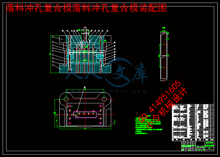
落料冲孔复合模落料冲孔复合模装配图.dwg---(点击预览)
落料冲孔复合模垫板2.dwg---(点击预览)
落料冲孔复合模垫板1.dwg---(点击预览)
落料冲孔复合模卸料板.dwg---(点击预览)
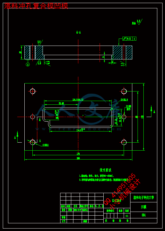
落料冲孔复合模凹模.dwg---(点击预览)
落料冲孔复合模凸模固定板.dwg---(点击预览)
落料冲孔复合模凸模2.dwg---(点击预览)
落料冲孔复合模凸凹模固定板.dwg---(点击预览)
落料冲孔复合模凸凹模.dwg---(点击预览)
落料冲孔复合模下模座1.dwg---(点击预览)
弯曲翻边复合模-翻边凸模.dwg---(点击预览)
弯曲翻边复合模-模柄.dwg---(点击预览)
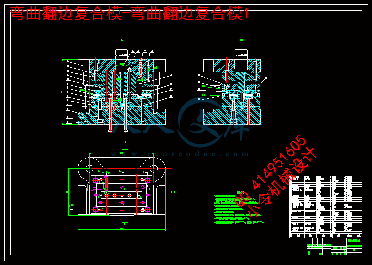
弯曲翻边复合模-弯曲翻边复合模1.dwg---(点击预览)
弯曲翻边复合模-垫板.dwg---(点击预览)
弯曲翻边复合模-凹模1.dwg---(点击预览)
弯曲翻边复合模-凸凹模.dwg---(点击预览)
弯曲翻边复合模-凸凹固定板.dwg---(点击预览)
弯曲翻边复合模-下模座2.dwg---(点击预览)
弯曲翻边复合模-上模座2.dwg---(点击预览)
开题报告.doc---(点击预览)
冷凝器侧板工件图.dwg---(点击预览)
任务书.doc---(点击预览)
中期检查表.doc---(点击预览)
CAXA图纸
工件图
冷凝器侧板工件图.exb
弯曲翻边复合模
弯曲翻边复合模-上模座2.exb
弯曲翻边复合模-下模座2.exb
弯曲翻边复合模-凸凹固定板.exb
弯曲翻边复合模-凸凹模.exb
弯曲翻边复合模-凹模1.exb
弯曲翻边复合模-垫板.exb
弯曲翻边复合模-弯曲翻边复合模1.exb
弯曲翻边复合模-模柄.exb
弯曲翻边复合模-翻边凸模.exb
落料冲孔复合模
落料冲孔复合模下模座1.exb
落料冲孔复合模凸凹模.exb
落料冲孔复合模凸凹模固定板.exb
落料冲孔复合模凸模2.exb
落料冲孔复合模凸模固定板.exb
落料冲孔复合模凹模.exb
落料冲孔复合模卸料板.exb
落料冲孔复合模垫板1.exb
落料冲孔复合模垫板2.exb
落料冲孔复合模落料冲孔复合模装配图.exb
英文翻译
压缩包内文档预览:
预览图 预览图 预览图 预览图 预览图 预览图
编号:443480    类型:共享资源    大小:3.79MB    格式:RAR    上传时间:2015-06-24 上传人:好资料QQ****51605 IP属地:江苏
45
积分
关 键 词:
冷凝器 冲压 模具设计 制造 工艺 分析 全套 cad 图纸 毕业 答辩 论文 模具
资源描述:

摘  要


本次设计的任务是某冷凝器侧板冲压模具设计及制造工艺分析,根据冲压件的结构特点及技术要求,围绕如何提高生产率、降低生产成本、简化模具结构,对工件进行工艺分析,并提出了各种可能的冲压工艺方案,最终确定采用一套由落料、冲孔复合和弯曲、翻边复合组成的冲压工艺方案。

在工艺分析的基础上,计算工艺参数,详细设计了落料冲孔、弯曲翻边两套复合模具结构。在设计过程中,计算出了零件展开尺寸,并对模具的排样做出了合理的布置,使材料得到充分利用。通过计算各种冲裁力,对压力机进行合理吨位的选择,并确定了模具压力中心。再根据确定的工艺方案,进行模具的校核,最终,设计模具制造与装配工艺。

采用此工艺方案和模具结构,提高了冷凝器侧板的生产效率和产品质量。

关键词:冷凝器侧板;工艺分析;模具设计;落料冲孔复合模;弯曲翻边复合模


Abstract


The task of this design is design of Stamping die and manufacturing process analysis for Condenser side plate stamping die design. according to the structure of stamping parts and technical requirements, focusing on how to improve work efficiency and reduce the production cost and simplify the die structure, Process analysis was carried out on the workpieces, and puts forward the stamping process scheme for all possible, and ultimately determine the stamping process program with a set of blanking, punching composite and bending, flanging composite.

On the basis of technology analysis and calculation parameters, and the detailed design for blanking punching, bending, flanging two sets of compound die structure. In the process of design, calculated developed dimension of parts, and the layout of the mold made reasonable decorate for make full use of the material. By calculating the various blanking force on the tonnage presses a reasonable choice, and to determine the center of pressure of the mold. According to determine the processing plan, mold check, in the end, the design of mold manufacturing and assembly process.

With this process program and die structure, improved production efficiency and product quality condenser side plate.

Keywords:condenser side plate; process analysis; die design; blanking punching composite die; bending flanging composite die;


目    录


引言1

1毕业设计(论文)的要求与数据2

2零件的冲压工艺分析2

2.1制件总体方案分析2

2.2零件的力学性能分析2

2.3零件的精度和粗糙度3

2.4最小相对弯曲半径3

2.5最小弯曲边高度3

2.6最小圆角半径4

2.7冲裁件的最小孔直径4

2.8冲裁件的孔与孔之间,孔与边缘之间的最小距离4

2.9最大翻边高度4

3工艺方案的确定5

3.1冲压该零件所需要的基本工序5

3.2方案比较与确定5

4落料冲孔复合模设计6

4.1主要工艺参数计算6

4.1.1工件展开尺寸计算6

4.1.2排样设计与计算7

4.1.3冲裁力、卸料力、和推件力的计算8

4.1.4模具压力中心9

4.2压力机的选用11

4.2.1冲裁设备的选择11

4.2.2冲压设备规格的确定11

4.3模具刃口尺寸计算12

4.3.1刃口尺寸计算12

4.4模具设计13

4.4.1卸料装置13

4.4.2推件装置13

4.4.3凸凹模设计14

4.4.4凸模15

4.4.5凹模17

4.4.6模架的选择17

4.4.7模柄18

4.4.8固定件与定位元件19

4.4.9弹性元件20

4.4.10其他零件21

4.5模架闭合高度及压力机有关参数的校核22

4.5.1公称压力22

4.5.2滑块行程22

4.5.3闭合高度22

4.5.4压力机工作台面的尺寸23

4.6落料冲孔复合模总装图设计23

4.6.1落料冲孔复合模工作过程23

4.7主要零件加工工艺的编制24

4.8落料冲孔复合模的安装与调试28

4.8.1模具装配顺序28

4.8.2模具的调试28

5翻边弯曲复合模29

5.1模具工作部分尺寸计算29

5.1.1弯曲工作部分计算29

5.1.2翻边刃口尺寸29

5.1.3弯曲时模具的圆角半径与凹模深度30

5.1.4弯曲回弹量30

5.2冲压力的计算和设备的选择30

5.2.1翻边力的计算30

5.2.2弯曲力的计算30

5.2.3选择冲压设备31

5.3模具设计32

5.3.1翻边凸模32

5.3.2凸凹模32

5.3.3凹模33

5.3.4凸模33

5.3.5凹模固定板34

5.3.6卸料装置34

5.3.7顶出装置34

5.3.8模柄35

5.3.9模架36

5.3.10固定于定位元件36

5.3.11其他零件36

5.4模具闭合高度和压力机有关参数的校核37

5.4.1公称压力37

5.4.2滑块行程37

5.4.3闭合高度37

5.4.4压力机工作台面的尺寸38

5.5弯曲翻边复合模总装图设计38

5.5.1弯曲翻边复合模的工作过程39

5.6主要零件加工工艺的编制39

5.7弯曲翻边复合模的安装与调整42

5.7.1模具的调整42

6总结45

谢  辞46

参考文献47


引言

在现代社会中,科技的进步促使工业生产行业发展得突飞猛进,许许多多的新鲜血液注入,实现了很多新型工艺、新型设备、新型技术以及新型材料在工业生产行业中的应用。从而使得冲压这项技术的不断改进与创新,模具设计及制造的水平实现快速的提升。

冲压加工应具有的三要素是:冲压设备、冲压模具以及冲压材料。而冲模是将金属或非金属材料单个加工及批量加工成型所需要冲件的专门的工具。只有合理的设计冲模、选择合适的冲压设备,并将它们安装调试准确,才能冲压出合格的制件。而冲压技术广泛运用于板料的加工中冲压成型中,在现代汽车、电器、航空等行业中,广泛应用到钣金件。而冲模在冲压工艺中非常重要,如果用不符合要求的冲模对工件进行加工,就会使得冲压件的质量不能达到设计要求,且进行批量冲压生产时效率极其低。可见,冲模在冲压加工中占有举足轻重的地位。在现代工业中,更多的是要求产品生产成本更加经济,生产周期越短越好,只有这样,才能在工业技术飞速发展的今天立于不败之地。当今工业生产的先进设计技术和新工艺的发展运用在模具的设计和制造中,让人们更能体会到模具在现代工业中的实用价值。

如今工业生产中,人们运用计算机技术和制造技术有机结合,实现了模具设计、制造加工一体化,与运用传统制造相比较,产品生产周期大大缩短了,产品质量有了很显著的提高,生产的成本与降低了很多,为工厂带来了更大的竞争优势和更高的经济效益。而我国的模具制造技术相对于发达国家而言,还存在着非常大的差距,根本无法满足国内市场对模具的需求,许多高精密等高档模具还需要从国外进口。我国的制造业技术正在迅猛发展,且模具制造在冲压加工行业在机械制造中扮演着越来越重要的角色,在市场环境高速发展的趋势下,不久的将来,我国将由模具大国向模具强国渐渐转变。

作为机械制造行业的后辈,学习模具相关的知识就显得尤为重要。本次设计是空调中常应用到的冷凝器侧板的冲压模设计,所以设计的任务主要是模具类型的选择和工作部分的制造,借此设计以巩固之前所学的模具知识。在满足工艺要求的基础上,尽可能使设计的模具结构简单,操作安全,还需要考虑模具的制造周期以及经济性是否符合现代工业的要求。这样不仅能设计和制造出先进的模具,也能充分地利用现代科技为工业的发展提供技术支持。


内容简介:
Journal of Materials Processing Technology 182 (2007) 456461A short note on an intelligent system for selection ofmaterials for progressive die componentsS. Kumara, R. SinghbaDepartment of Mechanical Engineering, Hindu College of Engineering, Sonepat, Haryana, IndiabDepartment of Mechanical Engineering, CRSCE, Murthal, Haryana, IndiaReceived 10 January 2006; received in revised form 15 August 2006; accepted 11 September 2006AbstractSelection of materials for die components is an important activity during progressive die design in stamping industries. This paper presentsan intelligent system for selection of materials for progressive die components. The proposed system SMPDC comprises of two knowledge basemodules, namely DIEMAT and SELHRD. The module DIEMAT is designed for selection of materials for both active and inactive componentsof progressive die. The module SELHRD is developed for determination of hardness range of materials for active components of progressive die.Knowledgeforboththemodulesoftheproposedsystemisacquired,analyzed,tabulatedandincorporatedintoasetofproductionrulesofIF-THENvariety. The system is coded in the AutoLISP language and loaded into the prompt area of AutoCAD. The system is designed to interact with theuser through the user interface. The usefulness of the proposed system is demonstrated through a sample run using an example of an industrialcomponent. The knowledge base of the system can be modified depending upon the availability of new materials and advancement in technology. 2006 Elsevier B.V. All rights reserved.Keywords: Progressive die; Material selection; Knowledge base; Intelligent system1. IntroductionProgressive die is widely used for mass production of sheetmetal components due to its high productivity, high precisionand relatively economic cost in terms of per piece of prod-uct. The design of die components and their material selec-tion are major activities during progressive die design 1.The selection of proper materials for progressive die com-ponents essentially increases the die life and hence reducesthe cost of production of sheet metal parts. Traditional meth-ods for carrying out this important activity are dependent onthe vast experience and depth of knowledge of die designexperts. Most of the times, material selection for progressivedie components is carried out manually using die design hand-books,materialhandbooks,thumb-rulesandheuristics.Existingcomputer-aided die design systems have still not fully dealtwith the core die design issue of material selection for pro-gressive die components. Some existing CAD/CAM systemsfor progressive dies 24 are able to generate bill of materials,Corresponding author. Tel.: +91 130 2210756; fax: +91 130 2210755.E-mail address: skbudhwar2003yahoo.co.in (S. Kumar).however, these systems do not take in account the availabil-ity of other suitable materials for the choice of user for betterperformance of die components and hence the long life of pro-gressivedie.Further,thesesystemsdonothaveevenknowledgebase consisting of experienced knowledge of domain expertsin material selection for progressive die components. World-wide researchers 5,6 have stressed to apply research effortsfor capturing and documenting the invaluable practical knowl-edge of experienced die designers and toolmakers through theapplicationsofartificialintelligence(AI)techniques.Thehighlyexperience based progressive die design activities such as mate-rial selection of die components can be simplified by usingknowledge-based system (KBS) or intelligent system approachDevelopment of such system can prove a landmark to ease thecomplexitiesinvolvedintheprocessofmaterialselectionfordiecomponents.Althoughlonglifeofallthecomponentsofprogressivedieisdesirable, however special due attention is required to improvethe life of active components (i.e. punch and die/inserts). Forselecting the suitable material for a progressive die component,the die designer properly investigates the functional require-mentsofthatcomponentandthenacriticalstudyiscarriedouttoidentify the required mechanical propertiesand possiblecauses,0924-0136/$ see front matter 2006 Elsevier B.V. All rights reserved.doi:10.1016/j.jmatprotec.2006.09.004S. Kumar, R. Singh / Journal of Materials Processing Technology 182 (2007) 456461457which may result the failure of the component. The selection ofmaterial for a given application depends on which failure mech-anisms dominate. The basic idea of a die designer is to select asuitable material such that all other failure mechanisms exceptwear are eliminated. The wear can then be optimized to matchthe required production quantity of sheet metal parts. To obtainlongerdielifeandhencehigherproductivity,toolsteelsarebeingwidely used as materials for die components. One of the mostimportant advantages of using steels as cutting tool materialsis that, they are originally soft and machinable, by applyingsuitable heat treatment, they become extremely hard and wearresistant. Selection of suitable hardness range of selected mate-rials of die components depends on the geometry of the part tobe manufactured on progressive die. The specific objective ofthe present work is the development of an intelligent system forselection of materials for progressive die components to assistthe die designers and toolmakers working in small and mediumsize sheet metal industries. A brief description of the procedureTable 1A sample of production rules incorporated in module DIEMATS. no.IFTHEN1Sheet material=Al or Cu or brass or Pb or berylliumcopperSelect an easily available material for punch and die/inserts from the following:EN-31 (5660 HRC) (AISI 52100) ORUHB-ARNE (5462 HRC) (AISI O1, W.-Nr. 1.2510)5Shear strength of sheet material (kgf/mm2)20Type of operations=shearingProduction quantity100,0002Sheet material=mild steel or stainless steel oraustenitic stainless steel or hardened steel or CRCAor spring steelSelect an easily available material for punch and die/inserts from the following:SEVERKER 3 (6064 HRC) (AISI D6 (D3), W.-Nr. 1.2436, JIS-SKD2) ORUHB-VANADIS 6 (6264 HRC) ORUHB-VANADIS 10 (6064 HRC)301,000,0003Sheet material=Al or Cu or brass or Pb or berylliumcopperSelect an easily available material for punch and die/inserts from the following:EN-31 (5660 HRC) (AISI 52100) ORUHB-ARNE (5462 HRC) (AISI O1, W.-Nr. 1.2510) ORUHB-CALMAX (5659 HRC)5Shear strength of sheet material (kgf/mm2)20Type of operations=forming or forming andshearing bothProduction quantity 100,0004Sheet material=mild steel or stainless steel oraustenitic stainless steel or hardened steel or CRCAor spring steelSelect an easily available material for punch and die/inserts from the following:SEVERKER 21 (5862 HRC) (AISI D2, W.-Nr. 1.2379, JIS-SKD11) ORAISI A2 (5862 HRC) (UHB-RIGOR, W.-Nr. 1.2363)30Shear strength of sheet material (kgf/mm2)70Type of operations=forming or forming andshearing both100,0002mmUse lower limit of hardness=upper limit of hardness of selected material-4.0Sheet thickness5mmUse upper limit of hardness=upper limit of hardness of selected materialGeometry of blanked part=normalHardness range of selected material in HRC45Sheet thickness2mmUse same range of hardness as mentioned with the selected materialSheet thickness5mmGeometry of blanked part=complicatedHardness range of selected material in HRC66Sheet thickness2mmUse lower limit of hardness=upper limit of hardness of selected material-6.0Sheet thickness5mmUse upper limit of hardness=upper limit of hardness of selected materialGeometry of blanked part=complicatedHardness range of selected material in HRC67Sheet thickness5mmUse lower limit of hardness=upper limit of hardness of selected material-8.0Sheet thickness8mmUse upper limit of hardness=upper limit of hardness of selected materialGeometry of blanked part=complicatedHardness range of selected material in HRC88Sheet thickness8mmUse same range of hardness as mentioned with the selected materialGeometry of blanked part=simple or normal or complicatedS. Kumar, R. Singh / Journal of Materials Processing Technology 182 (2007) 456461459Fig. 1. Execution of proposed intelligent system SMPDC.system SMPDC comprises of more than 60 production rules.However, the system is flexible enough as its knowledge basecan be updated and modified, if necessary, on the advancementin technology and availability of new materials in future havingbetter performance than recommended by the proposed system.Both the modules of the proposed system are designed to beinteractive in nature to enable the user to input the essentialsheet metal component data; and to displays the optimal deci-sion choices for the users benefit. The former is accomplishedby flashing AutoCAD prompts to the user at appropriate stagesduring a consultation to feed data items. Messages or items ofadvices are likewise flashed into the computer screen wheneverrelevant production rules are fired. The system can be loaded byentering the command (load “A: SMPDC.LSP”) in the promptarea of AutoCAD. The execution of the system is demonstratedthrough a flow chart as shown in Fig. 1. The output of the pro-gram includes the intelligent advices for selection of materialsfor active elements (i.e. punch and die/inserts) and inactive ele-ments (i.e. plate elements, guiding and locating elements) andclose hardness range of the material selected for active elementsof progressive die.3. Sample run of the proposed systemTheproposedsystemisimplementedonPC(Pentium4CPU,2.4GHz,256MBofRAM)withAutodeskAutoCAD2004.Thesystem has been tested for different types of sheet metal partsfor the problem of material selection for progressive die compo-nents.Typicalprompts,userresponsesandtherecommendationsobtained by the user during the execution of the proposed intel-ligent system SMPDC for an example component (Fig. 2) aregiveninTable3.Therecommendedmaterialsbythesystemwerefound to be reasonably close to those actually used in indus-try (Indo-Asian Fuse Gear Private Limited, Murthal, Haryana,India) for the example component.Fig. 2. Example component (all dimensions in mm): Brass, sheet thick-ness=0.6mm.460S. Kumar, R. Singh / Journal of Materials Processing Technology 182 (2007) 456461Table 3Typical prompts, user responses and expert advice generated during execution of the proposed intelligent system SMPDC for example componentPromptExample data entryAdvice to the user(Load “A: SMPDC.LSP”)Please enter command SMPDCSMPDCWelcome to the module SMPDC. Please enter command DIEMATDIEMATPlease enter sheet materialBrassPlease enter the type of operationsShearingPlease enter shear strength of sheet material15kgf/mm2Please enter required production quantity ofsheet metal parts90,000Please select an easily available material for punch and die/inserts from the following:EN-31 (5660 HRC) (AISI 52100) OR UHB-ARNE (5462 HRC) (AISI O1, W.-Nr.1.2510)Please enter the category of inactiveelements (i.e. plate elements, locatingand guiding elements)Plate elementsPlease select an easily available material for plate elements from the following: Top plate and bottom plate: Mild steel OR UHB-11 (AISI 1148) OR EN-31 (AISI52100) OR UHB-FORMAX (W. Nr.-10050, SS-2172) OR EN-8 (AISI 1040) Punch plate: Mild steel OR EN-8 (AISI 1040) OR UHB-ARNE (AISI O1, W.-Nr.1.2510) Punch back plate: EN-31 (AISI 52100) OR UHB-ARNE (AISI O1, W.-Nr. 1.2510) Stripper plate: EN-31 (AISI 52100) OR UHB-11 (AISI 1148) Die support plate: EN-31 (AISI 52100)Please enter the category of inactive elementsGuiding and locatingelementsPlease select an easily available material for guiding and locating elements from thefollowing: Die gages (Ra=0.10.4?m) (4850 HRC): EN-31 (AISI 52100) OR UHB-11 (AISI1148) Die stops (Ra=0.10.4?m) (4246 HRC): EN-31 (AISI 52100) OR EN-47 (AISI6150) Lifter (Ra=0.10.4?m) (5255 HRC): HCHCr OR SEVERKER-21 (AISI D2, W.-Nr.1.2379, JIS-SKD11) OR H.S.S. Guide pin and guide piller pin (Ra=0.10.4?m) (5052 HRC): EN-353 Ball cage (Ra=0.0250.05?m): Aluminium OR Brass OR plastics Sleeve (Ra=0.10.4?m): EN-31 (AISI 52100) Shank (Ra=0.83.2?m): Mild steel Dowel pins (Ra=0.83.2?m) (5052 HRC): C-40 OR EN-8 (AISI 1040) OR EN-9(AISI 1055) OR Silver steelPlease enter command SELHRDSELHRDPlease enter the selected material of punchand die/insertsEN-31 (5660 HRC)Typical analysis of EN-31: C=0.90/1.2, Si=0.10/0.35, Mn=0.30/0.75, Cr=1.0/1.6, Sand P each=0.025 (maximum)Please enter sheet thickness (mm)0.6Please enter the geometry of blanked part(i.e. simple/normal/complicated)NormalPlease enter the difference of upper limitand lower limit of hardness (HRC) ofselected material4.0Use lower limit of hardness=upper limit of hardness of selected material-2.0, andUse upper limit of hardness same as the upper limit of hardness of selected material4. ConclusionThe proposed system is capable of giving expert advice onselectionofmaterialsforprogressivediecomponentsandselec-tion of close hardness range of materials during the designstage of progressive dies. The user has been provided an optionto select easily available materials from the advice receivedby the proposed system and then a bill of materials can beprepared suitably. The system has been tested for variety ofsheet metal components and proved to be powerful and easyto handle because of its rich knowledge base and highly interac-tive nature. The sample run of the system using an industrialexample component has demonstrated the usefulness of thesystem. The system supports mainly tool steels, however, itsknowledge base can be modified and updated depending uponthe availability of new material
温馨提示:
1: 本站所有资源如无特殊说明,都需要本地电脑安装OFFICE2007和PDF阅读器。图纸软件为CAD,CAXA,PROE,UG,SolidWorks等.压缩文件请下载最新的WinRAR软件解压。
2: 本站的文档不包含任何第三方提供的附件图纸等,如果需要附件,请联系上传者。文件的所有权益归上传用户所有。
3.本站RAR压缩包中若带图纸,网页内容里面会有图纸预览,若没有图纸预览就没有图纸。
4. 未经权益所有人同意不得将文件中的内容挪作商业或盈利用途。
5. 人人文库网仅提供信息存储空间,仅对用户上传内容的表现方式做保护处理,对用户上传分享的文档内容本身不做任何修改或编辑,并不能对任何下载内容负责。
6. 下载文件中如有侵权或不适当内容,请与我们联系,我们立即纠正。
7. 本站不保证下载资源的准确性、安全性和完整性, 同时也不承担用户因使用这些下载资源对自己和他人造成任何形式的伤害或损失。
提示  人人文库网所有资源均是用户自行上传分享,仅供网友学习交流,未经上传用户书面授权,请勿作他用。
关于本文
本文标题:某冷凝器侧板冲压模具设计及制造工艺分析【20张CAD图纸+毕业答辩论文】【冲压模具】
链接地址:https://www.renrendoc.com/p-443480.html

官方联系方式

2:不支持迅雷下载,请使用浏览器下载   
3:不支持QQ浏览器下载,请用其他浏览器   
4:下载后的文档和图纸-无水印   
5:文档经过压缩,下载后原文更清晰   
关于我们 - 网站声明 - 网站地图 - 资源地图 - 友情链接 - 网站客服 - 联系我们

网站客服QQ:2881952447     

copyright@ 2020-2025  renrendoc.com 人人文库版权所有   联系电话:400-852-1180

备案号:蜀ICP备2022000484号-2       经营许可证: 川B2-20220663       公网安备川公网安备: 51019002004831号

本站为文档C2C交易模式,即用户上传的文档直接被用户下载,本站只是中间服务平台,本站所有文档下载所得的收益归上传人(含作者)所有。人人文库网仅提供信息存储空间,仅对用户上传内容的表现方式做保护处理,对上载内容本身不做任何修改或编辑。若文档所含内容侵犯了您的版权或隐私,请立即通知人人文库网,我们立即给予删除!