进度计划表.doc

某冷凝器侧板冲压模具设计及制造工艺分析【20张CAD图纸+毕业答辩论文】【冲压模具】

收藏

资源目录
跳过导航链接。
某冷凝器侧板冲压模具设计及制造工艺分析【全套CAD图纸+毕业答辩论文】【冲压模具】.rar
进度计划表.doc---(点击预览)
说明书.docx---(点击预览)
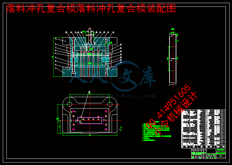
落料冲孔复合模落料冲孔复合模装配图.dwg---(点击预览)
落料冲孔复合模垫板2.dwg---(点击预览)
落料冲孔复合模垫板1.dwg---(点击预览)
落料冲孔复合模卸料板.dwg---(点击预览)
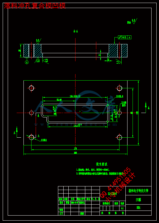
落料冲孔复合模凹模.dwg---(点击预览)
落料冲孔复合模凸模固定板.dwg---(点击预览)
落料冲孔复合模凸模2.dwg---(点击预览)
落料冲孔复合模凸凹模固定板.dwg---(点击预览)
落料冲孔复合模凸凹模.dwg---(点击预览)
落料冲孔复合模下模座1.dwg---(点击预览)
弯曲翻边复合模-翻边凸模.dwg---(点击预览)
弯曲翻边复合模-模柄.dwg---(点击预览)
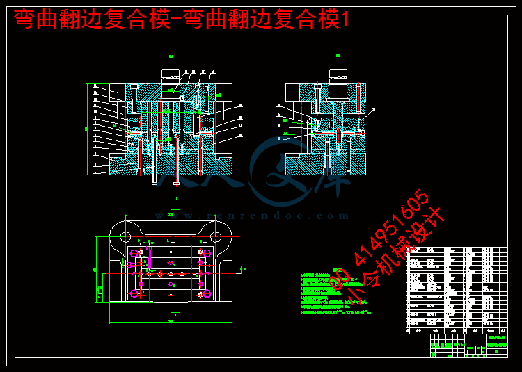
弯曲翻边复合模-弯曲翻边复合模1.dwg---(点击预览)
弯曲翻边复合模-垫板.dwg---(点击预览)
弯曲翻边复合模-凹模1.dwg---(点击预览)
弯曲翻边复合模-凸凹模.dwg---(点击预览)
弯曲翻边复合模-凸凹固定板.dwg---(点击预览)
弯曲翻边复合模-下模座2.dwg---(点击预览)
弯曲翻边复合模-上模座2.dwg---(点击预览)
开题报告.doc---(点击预览)
冷凝器侧板工件图.dwg---(点击预览)
任务书.doc---(点击预览)
中期检查表.doc---(点击预览)
CAXA图纸
工件图
冷凝器侧板工件图.exb
弯曲翻边复合模
弯曲翻边复合模-上模座2.exb
弯曲翻边复合模-下模座2.exb
弯曲翻边复合模-凸凹固定板.exb
弯曲翻边复合模-凸凹模.exb
弯曲翻边复合模-凹模1.exb
弯曲翻边复合模-垫板.exb
弯曲翻边复合模-弯曲翻边复合模1.exb
弯曲翻边复合模-模柄.exb
弯曲翻边复合模-翻边凸模.exb
落料冲孔复合模
落料冲孔复合模下模座1.exb
落料冲孔复合模凸凹模.exb
落料冲孔复合模凸凹模固定板.exb
落料冲孔复合模凸模2.exb
落料冲孔复合模凸模固定板.exb
落料冲孔复合模凹模.exb
落料冲孔复合模卸料板.exb
落料冲孔复合模垫板1.exb
落料冲孔复合模垫板2.exb
落料冲孔复合模落料冲孔复合模装配图.exb
英文翻译
压缩包内文档预览:
预览图 预览图 预览图
编号:443480    类型:共享资源    大小:3.79MB    格式:RAR    上传时间:2015-06-24 上传人:好资料QQ****51605 IP属地:江苏
45
积分
关 键 词:
冷凝器 冲压 模具设计 制造 工艺 分析 全套 cad 图纸 毕业 答辩 论文 模具
资源描述:

摘  要


本次设计的任务是某冷凝器侧板冲压模具设计及制造工艺分析,根据冲压件的结构特点及技术要求,围绕如何提高生产率、降低生产成本、简化模具结构,对工件进行工艺分析,并提出了各种可能的冲压工艺方案,最终确定采用一套由落料、冲孔复合和弯曲、翻边复合组成的冲压工艺方案。

在工艺分析的基础上,计算工艺参数,详细设计了落料冲孔、弯曲翻边两套复合模具结构。在设计过程中,计算出了零件展开尺寸,并对模具的排样做出了合理的布置,使材料得到充分利用。通过计算各种冲裁力,对压力机进行合理吨位的选择,并确定了模具压力中心。再根据确定的工艺方案,进行模具的校核,最终,设计模具制造与装配工艺。

采用此工艺方案和模具结构,提高了冷凝器侧板的生产效率和产品质量。

关键词:冷凝器侧板;工艺分析;模具设计;落料冲孔复合模;弯曲翻边复合模


Abstract


The task of this design is design of Stamping die and manufacturing process analysis for Condenser side plate stamping die design. according to the structure of stamping parts and technical requirements, focusing on how to improve work efficiency and reduce the production cost and simplify the die structure, Process analysis was carried out on the workpieces, and puts forward the stamping process scheme for all possible, and ultimately determine the stamping process program with a set of blanking, punching composite and bending, flanging composite.

On the basis of technology analysis and calculation parameters, and the detailed design for blanking punching, bending, flanging two sets of compound die structure. In the process of design, calculated developed dimension of parts, and the layout of the mold made reasonable decorate for make full use of the material. By calculating the various blanking force on the tonnage presses a reasonable choice, and to determine the center of pressure of the mold. According to determine the processing plan, mold check, in the end, the design of mold manufacturing and assembly process.

With this process program and die structure, improved production efficiency and product quality condenser side plate.

Keywords:condenser side plate; process analysis; die design; blanking punching composite die; bending flanging composite die;


目    录


引言1

1毕业设计(论文)的要求与数据2

2零件的冲压工艺分析2

2.1制件总体方案分析2

2.2零件的力学性能分析2

2.3零件的精度和粗糙度3

2.4最小相对弯曲半径3

2.5最小弯曲边高度3

2.6最小圆角半径4

2.7冲裁件的最小孔直径4

2.8冲裁件的孔与孔之间,孔与边缘之间的最小距离4

2.9最大翻边高度4

3工艺方案的确定5

3.1冲压该零件所需要的基本工序5

3.2方案比较与确定5

4落料冲孔复合模设计6

4.1主要工艺参数计算6

4.1.1工件展开尺寸计算6

4.1.2排样设计与计算7

4.1.3冲裁力、卸料力、和推件力的计算8

4.1.4模具压力中心9

4.2压力机的选用11

4.2.1冲裁设备的选择11

4.2.2冲压设备规格的确定11

4.3模具刃口尺寸计算12

4.3.1刃口尺寸计算12

4.4模具设计13

4.4.1卸料装置13

4.4.2推件装置13

4.4.3凸凹模设计14

4.4.4凸模15

4.4.5凹模17

4.4.6模架的选择17

4.4.7模柄18

4.4.8固定件与定位元件19

4.4.9弹性元件20

4.4.10其他零件21

4.5模架闭合高度及压力机有关参数的校核22

4.5.1公称压力22

4.5.2滑块行程22

4.5.3闭合高度22

4.5.4压力机工作台面的尺寸23

4.6落料冲孔复合模总装图设计23

4.6.1落料冲孔复合模工作过程23

4.7主要零件加工工艺的编制24

4.8落料冲孔复合模的安装与调试28

4.8.1模具装配顺序28

4.8.2模具的调试28

5翻边弯曲复合模29

5.1模具工作部分尺寸计算29

5.1.1弯曲工作部分计算29

5.1.2翻边刃口尺寸29

5.1.3弯曲时模具的圆角半径与凹模深度30

5.1.4弯曲回弹量30

5.2冲压力的计算和设备的选择30

5.2.1翻边力的计算30

5.2.2弯曲力的计算30

5.2.3选择冲压设备31

5.3模具设计32

5.3.1翻边凸模32

5.3.2凸凹模32

5.3.3凹模33

5.3.4凸模33

5.3.5凹模固定板34

5.3.6卸料装置34

5.3.7顶出装置34

5.3.8模柄35

5.3.9模架36

5.3.10固定于定位元件36

5.3.11其他零件36

5.4模具闭合高度和压力机有关参数的校核37

5.4.1公称压力37

5.4.2滑块行程37

5.4.3闭合高度37

5.4.4压力机工作台面的尺寸38

5.5弯曲翻边复合模总装图设计38

5.5.1弯曲翻边复合模的工作过程39

5.6主要零件加工工艺的编制39

5.7弯曲翻边复合模的安装与调整42

5.7.1模具的调整42

6总结45

谢  辞46

参考文献47


引言

在现代社会中,科技的进步促使工业生产行业发展得突飞猛进,许许多多的新鲜血液注入,实现了很多新型工艺、新型设备、新型技术以及新型材料在工业生产行业中的应用。从而使得冲压这项技术的不断改进与创新,模具设计及制造的水平实现快速的提升。

冲压加工应具有的三要素是:冲压设备、冲压模具以及冲压材料。而冲模是将金属或非金属材料单个加工及批量加工成型所需要冲件的专门的工具。只有合理的设计冲模、选择合适的冲压设备,并将它们安装调试准确,才能冲压出合格的制件。而冲压技术广泛运用于板料的加工中冲压成型中,在现代汽车、电器、航空等行业中,广泛应用到钣金件。而冲模在冲压工艺中非常重要,如果用不符合要求的冲模对工件进行加工,就会使得冲压件的质量不能达到设计要求,且进行批量冲压生产时效率极其低。可见,冲模在冲压加工中占有举足轻重的地位。在现代工业中,更多的是要求产品生产成本更加经济,生产周期越短越好,只有这样,才能在工业技术飞速发展的今天立于不败之地。当今工业生产的先进设计技术和新工艺的发展运用在模具的设计和制造中,让人们更能体会到模具在现代工业中的实用价值。

如今工业生产中,人们运用计算机技术和制造技术有机结合,实现了模具设计、制造加工一体化,与运用传统制造相比较,产品生产周期大大缩短了,产品质量有了很显著的提高,生产的成本与降低了很多,为工厂带来了更大的竞争优势和更高的经济效益。而我国的模具制造技术相对于发达国家而言,还存在着非常大的差距,根本无法满足国内市场对模具的需求,许多高精密等高档模具还需要从国外进口。我国的制造业技术正在迅猛发展,且模具制造在冲压加工行业在机械制造中扮演着越来越重要的角色,在市场环境高速发展的趋势下,不久的将来,我国将由模具大国向模具强国渐渐转变。

作为机械制造行业的后辈,学习模具相关的知识就显得尤为重要。本次设计是空调中常应用到的冷凝器侧板的冲压模设计,所以设计的任务主要是模具类型的选择和工作部分的制造,借此设计以巩固之前所学的模具知识。在满足工艺要求的基础上,尽可能使设计的模具结构简单,操作安全,还需要考虑模具的制造周期以及经济性是否符合现代工业的要求。这样不仅能设计和制造出先进的模具,也能充分地利用现代科技为工业的发展提供技术支持。


内容简介:
journal of materials processing technology 1 9 5 ( 2 0 0 8 ) 94100journal homepage: /locate/jmatprotecAutomation of strip-layout design for sheet metalwork on progressive dieS. Kumara, R. SinghbaDepartment of Mechanical Engineering, Hindu College of Engineering, Sonepat, Haryana, IndiabDepartment of Mechanical Engineering, CRSCE, Murthal, Haryana, Indiaa r t i c l ei n f oArticle history:Received 13 November 2006Accepted 18 April 2007Keywords:AutomationStrip-layout designSheet metal workProgressive dieExpert systema b s t r a c tStrip-layout design is an important step in the planning stage of sheet metal work on pro-gressive die. It is an experience-driven activity and the quality of strip-layout is highlydependent on the knowledge and skill of die designers. This paper presents an expertsystem for automation of strip-layout design process. The proposed system is developedusing the production rule-based expert system approach of Artificial Intelligence (AI). Itcomprises six modules to impart expert advices to the user for identifying sheet metal oper-ations, sequencing of operations, selection of proper piloting scheme, number of stations,staging of operations on progressive die and selection of proper dimensions of stock strip.Finally, the system models the strip-layout automatically in the drawing editor of AutoCADusing the output data files of other modules. Usefulness of the system is demonstratedthrough an example of an industrial component. The system is flexible and has low cost ofimplementation. 2007 Elsevier B.V. All rights reserved.1.IntroductionStrip-layout design has an extreme importance during theplanning stage of progressive die design as the productivity,accuracy, cost and quality of a die mainly depends on thestrip-layout (Tor et al., 2005). Traditional strip-layout designis manual, highly experience-based activity and thereforetedious,timeconsuminganderror-prone(Lietal.,2002;Ridha,2003). Four decades earlier strip-layout problems were solvedmanually. The blanks cutting from cardboard were manip-ulated to obtain a good strip-layout. This trial and errorprocedure of obtaining suitable strip-layout with maximummaterial utilization is still being used in most of the smallscale and even in some medium scale sheet metal industriesworldwide. The quality of strip-layout achieved by using tra-ditional methods depends on the experience and knowledgeof designers. On the advent of computer aided design (CAD)Corresponding author. Tel.: +91 9416942082; fax: +91 1302212755.E-mail address: skbudhwar2003yahoo.co.in (S. Kumar).systems around 3 decades earlier, the process of strip-layoutdesign was somewhat made easier and the design lead-timewas reduced from days to hours. However, well-trained andexperienced die designers were still required to operate theseCAD systems. Most of the applications of CAD in strip-layoutdesign are aimed mainly at achieving better material utiliza-tion by rotating and placing the blanks as close as possiblein the strip. However, the strip-layout with maximum mate-rial saving may not be the best strip-layout, indeed the dieconstruction may become more complex, which could offsetthe savings due to material economy unless a large num-ber of parts are to be produced. The system developed bySchaffer (1971) in 1971 reported to calculate the stresses dueto bending moment on cantilevered die projections and if thesystem finds that the stress level is above the yield stressof die steel material, then the system distributes the cuttingoperations over several stages in order to keep the stresses0924-0136/$ see front matter 2007 Elsevier B.V. All rights reserved.doi:10.1016/j.jmatprotec.2007.04.119journal of materials processing technology 1 9 5 ( 2 0 0 8 ) 9410095Table 1 A sample of production rules incorporated in the proposed systemSerial numberIFTHEN10.001minimum accuracy required on part in mm0.2 andfeature required on part=hole or slot or internal contour cutRequired operation=piercing20.001minimum accuracy required on part in mm0.2 andfeature required on part=small cut or notch on externalboundary or contourRequired operation=notching30.001minimum accuracy required on part in mm0.2 andfeature required on part=complete cut on one side of partRequired operations=parting off/cut off4Required operations: notching, blanking/parting off, piercingPreferred sequence of operation: 1st, piercing;2nd, notching; 3rd, blanking/parting off5Number of holes exist on the part2, shape of holes=circular,diameter of holes1.0mm, hole pitch2.0 times of sheetthickness, distance of holes from the edge of part2.0 timessheet thickness, specified tolerance on holes0.05mm, andholes are located on opposite sides of the partSelect the two largest holes for piloting6There are suitable holes available in the componentPierce these holes at first station and use themfor piloting7The minimum distance between the edge of the internal featureand edge of die block2.0 times of sheet thickness (but not lessthan 3.0mm) OR there is any possibility of future engineeringchanges in the design of partLeft idle station8Required operations on part=notching (2), piercing (any numberof holes) and parting off; distance of hole(s) from edge of partand hole pitch2.0 times of sheet thicknessNumber of stations=5. Preferred staging: 1ststation, piercing; 2nd station, notching andpiloting; 3rd station, notching and piloting; 4thstation, parting off9Sheet thickness1.4mm; 25blank contour width75mm;sharp edge (along width of sheet) exists in the edgeperpendicular to the moving direction of the sheetSelect sheet width in mm=(blank contourwidth+3.2)10Sheet thickness0.8mm; blank contour length25mm; sharpedge (along length of sheet) exists in the edge parallel to themoving direction of the sheet (along width of sheet)Select feed distance in mm=(blank contourlength+2.0)within the reasonable limit. One of the limitations of the sys-tem is that it does not give any importance to the complexityof die and punches during staging of operations. Adachi etal. (1983) developed an integrated CAD system for design ofprogressive die. The system outputs also include generationof strip-layout for progressive die. But the user has to specifythe sequence of operations himself to obtain the strip-layout.Nee (1984a,b, 1985) developed some experimental packagesfor analysis on press capacity, the use of coiled or strip stockand cost factors in order to solve for near-optimum layout andnesting problems for both sheet metal and metal stampingblanks. All of his work focused on the general strip-layoutdesign process and the expert rules involved do not tackleother stamping operations such as piercing, bending, form-ing, etc. The system developed by Duffy and Sun (1991) usedknowledge-based system approach to generate strip-layoutfor progressive stamping dies. The system was implementedin IDL, which is a knowledge-based system language. The sys-tem has the capability to generate strip-layout; however, it hasnot been implemented and its capabilities in real life have notbeen tested. The Computer Aided Die Design System (CADDS)developed by Prasad and Somasundaram (1992) also has onemodule for the strip-layout for progressive die. In this module,the die type is selected, depending on the input parame-ters. If the selected die is progressive, strip development issubsequently carried out according to the rules incorporatedin the strip-layout module. But the major limitation of thesystem is that it supports mainly blanking and piercing opera-tions. Singh and Sekhon (2001) developed a low cost modellerfor two-dimensional metal stamping layouts. The software isbased on AutoCAD and AutoLISP. The system is capable ofmodeling circular, polygonal and components having curvedsegments. Alternative strip-layouts are also generated andtested for optimality. The main limitation of the system isthat it deals with single operation stamping dies. Kim etal. (2002) developed a system using AutoLISP language. Thesystem decides the sequencing process of electric productswith intricate piercing and bending operations by consider-ing several factors on bending and adopting fuzzy set theory.It constructs fuzzy matrix for calculating fuzzy relationshipvalue and determines the optimum bend by combining sev-eralruleswithfuzzyreasoning.Thestrip-layoutmoduleofthesystem is able to carry out bending and piercing operations of3D electric product. The main limitation of this system is thatit deals with only bending and piercing operations on progres-sive die. Venkata Rao (2004) presented a strip-layout selectionprocedure pertaining to metal die stamping work. The pro-cedure is based on analytic hierarchy process (AHP). But, thedeveloped procedure is applicable only for simple blankingand piercing dies. Chu et al. (2004) proposed a mathematicaltechnique capable of generating a stamping sequence auto-maticallyinthedesignofprogressivestampingdies.Agraphisused to represent a stamping part and define the relationshipsbetween its stamping features. The graph is partitioned intosets of mutually independent vertices using a clustering algo-rithm. Finally, the clustered sets are ordered to give the finalsequence of workstations. Completion and development of asoftware prototype of the system is still in progress and has96journal of materials processing technology 1 9 5 ( 2 0 0 8 ) 94100Fig. 1 Execution of the proposed system.to be tested against real industrial sheet metal parts havingdifferent shapes.The foregoing literature review reveals that only a fewresearch and development works have been carried out inthe area of automation of strip-layout design for sheet metalwork on progressive dies. Most of the works are concentratedon process planning for sheet metal blanking and piercingoperations. Some commercial computer aided systems areavailable to assist die designers but these are limited only tosimple calculations, strip nesting, retrieval of catalogue dataand compiled database of standard die components, none ofthem directly addressed the problem of strip-layout design.The dependence on experience coupled with the mobility ofdie designers in stamping industries has caused much incon-venience to the sheet metal industries all over the world.Therefore, it has become essential to capture knowledge andexperience of die designers into an expert system so that itcanberetainedandutilizedsuitablyforfutureapplicationanddevelopment purposes. Although some expert systems havebeen developed for die design area, but most of the researchworks are concentrated on nesting and process planning ofsheetmetalforminganddrawing.Nospecificsystemhasbeendeveloped for solving strip-layout design problem of progres-sive dies. To improve productivity and to build a computerintegrated manufacturing environment, automatic modelingof strip-layout design is essential. The objective of the devel-opment work presented in this paper is to concentrate on theautomationofstrip-layoutdesignusingproductionrule-basedexpert system approach of Artificial Intelligence (AI). The sys-tem is implemented on PC having AutoDesk AutoCAD 2004software and designed to be loaded in the prompt area ofAutoCAD.2.Recommendations for strip-layoutdesignStrip-layout design for progressive die is to arrange layout ofthe operations and subsequently determine the number ofstations required. For design of strip-layout, the die designerdetermines the sheet metal operations required for manu-facturing the parts, sequencing of operations, selection ofpiloting method, number of stations required and the oper-ations stamped at each station of progressive die. Strip-layoutis determined by the shape of a part and its technical require-ments. It is generally governed by the geometrical featuresjournal of materials processing technology 1 9 5 ( 2 0 0 8 ) 9410097Fig. 2 Example component (brass, sheetthickness=0.6mm).of the part, tolerance on dimensions of the part, direction ofsharp edge of stock strip and other technical requirements.One important, but very difficult task in strip-layout design isthe determination of a proper sequence of stamping opera-tions so that the part can be stamped correctly and efficiently.The sequence of operations on a strip and the details of eachoperation must be carefully developed to ensure that thedesign will produce good sheet metal parts without produc-tion or maintenance problems. Normally there is no uniquebest solution for the strip-layout design but certain commonrules can be used to guide the design of strip-layout. Some ofthe important rules generally used for strip-layout design areas follows:(1) Theinitialoperationssuchassidecutsorcropping,whichdonotdirectlyaffecttheshapeofthefinalproductshouldbe made in the first stage.(2) If there are suitable holes available in the sheet metalpart, these holes should be used for piloting; otherwiseexternal pilot holes should be introduced according tothe progression. Piercing of these pilot holes is done inthe first stage or just after cropping stage. The loca-tion of pilot holes should always be the far oppositesides of the strip, with the greatest possible gap inbetween. This is to secure the best fixation and position-ing of the strip, once the pilots engage in their respectiveopenings.(3) Distances between the holes punched on one stationmust be larger than a certain value to ensure the diestrength. Pierced holes may be distributed over severalstages, if they are closely located and functionally notrelated.(4) Holes with high position accuracy requirement should bepunched in one station.(5) Narrow slots and projections should not be allowed in adie as fracture may occur.(6) If the external profile of the blank is complex, then theprofile may be split into simple sections by projecting allthe vertices of the blank vertically up to the edge of thestrip.(7) Idle stations may be used to avoid crowding of punchesand die blocks together. An added advantage is thatFig. 3 Strip-layout generated by the proposed system forexample component.future engineering changes can be incorporated at lowcost.(8) Bending should preferably be done in the last station orprior to the parting stage, and the rest of the strip shouldbe arranged around such a requirement.(9) Finally, the parting off or blanking operation(s) and inter-nal holes used as semi-piloting holes (if any) should bestaged.(10) Sufficient bridge width should be used in order to providemaximum strength for the bridges.(11) Finally, design the strip in such a way that it enables thecomponent and scrapes to be ejected without interfer-ence.Pilotingisanimportantfactorinstrip-layoutdesignforpro-gressive die. The strip must be positioned accurately in eachstation so that the operations can be performed at the properlocations. The task of selection of piloting scheme shouldbe viewed as interdependent task in the strip-layout designprocess. A strip-layout design system should support directpiloting, semi-direct piloting and indirect piloting scheme. Aholeisconsideredtobesuitableforuseasapilotholeifitiscir-cular in shape, specified size tolerance is not high, big enoughfor use as a pilot hole, does not lie on the folded portion of theworkpiece, not too close to the edge of the workpiece, and nottoo close to another hole on the workpiece. From the list ofsuitable pilot holes, the best piloting holes should be selectedbased on the following priority:(1) If only one hole is available, it must be considered in thefirst instance.(2) If there are a number of holes, then the location of theseholes should be examined.98journal of materials processing technology 1 9 5 ( 2 0 0 8 ) 94100Table 2 Typical prompts, user responses and expert advices generated during execution of the proposed expert systemfor example component (Fig. 2)PromptExample data entryAdvice to the userPlease enter sheet materialBrassModel the blank using AutoCAD commandsPlease enter sheet thickness in mm0.6Please enter the command OPRPLANOPRPLANWelcome to the module OPRPLAN, developed foridentification of operationsEnter type of feedAutomaticIs camber present in the strip?NoPlease enter the geometrical features of the part in formof questionnaire (Yes/No)Is small cut(s) or notch(es) existing on externalboundary or contour?YesIs hole(s) or slot(s) or internal contour cut exist-ing?YesIs sheet edge(s) rough?NoDoes bend along a straight axis exists?NoIs curved bend or forming existing?NoIs complete cut required at any side of blank?YesFollowing operations are requirednotching, piercingand parting off. Please enter the command OPRSEQOPRSEQWelcome to the module OPRSEQ developed foridentifying the proper sequence of operations. Theproper sequence of operations is as follows: 1st,piercing; 2nd, notching; 3rd, parting off. Please enter thecommand PLTSELPLTSELWelcome to the module PLTSEL, developed for selectionof piloting schemeIs any folded portion on the part?NoEnter specified tolerance (in mm) on hole(s)0.05Are holes located on opposite sides of the part?YesSelect the two largest holes located on opposite sides ofpart for piloting (direct piloting). Please enter thecommand OPRSTAGEOPRSTAGEWelcome to the module OPRSTAGE developed fordeciding number of stations and staging of operationson progressive die. Please enter the commandOPRSTAGE1OPRSTAGE1Is the center-to-center distance between holeshas tolerance range within 0.05mm?YesPierce these holes at the same stationAre there any complex or weak sections in theexternal profile of the part?NoIs the minimum distance between the edge of theinternalfeatureandedgeofdieblock2.0timesof sheet thickness (but not less than 3.0mm)?R There is any possibility of future engineeringchanges in the part?NoPlease enter command OPRSTAGE2OPRSTAGE2Enter number of notches in the part2Enter number of holes in the part2Number of stations required=5. Preferred staging ofoperations: 1st station: piercing; 2nd station: punching,notching and piloting; 3rd station: notching andpiloting; 4th station: notching and piloting; 5th station:parting off. Please enter command SWLSELSWLSELWelcome to the module SWLSEL developed fordetermining strip width and feed distanceEnter blank contour width in mm62.0Enter the sharp edge direction of the sheet (alongwidth of sheet)ptmdsaSelect strip width in mm=65.2Enter blank contour length in mm12.7Enterthesharpedgedirectionofthemovingsheet(along the length of sheet)partmdsbSelect feed distance (or pitch) in mm=14.7. Please entercommand STRPLYTSTRPLYTWelcome to the module STRPLYT, developed forautomatic modeling of strip-layoutSelect a start point(220,100)The strip-layout modelled by the system is shown inthe drawing editor of AutoCADaptmds, perpendicular to the moving direction of strip.bpartmds, parallel to the moving direction of strip.journal of materials processing technology 1 9 5 ( 2 0 0 8 ) 9410099(a) If holes are located in the same direction as feed ofthe strip, then select one hole, which is nearest to thecentroid of the part.(b) If holes are located in the perpendicular direction asthat of feed, then select the two largest holes (whichare equal in diameter) and that are located at a dis-tance at least two times of sheet thickness.(3) Select the two largest holes (the diameters of which arewithin a pre-set percentage of each other), which satisfythe earlier conditions.Keeping in view of the above basic guidelines and recom-mendations, an expert system for automation of strip-layoutdesignforsheetmetalworkonprogressivediehasbeendevel-oped. A brief description of the proposed system is given asunder.3.Development and execution of theproposed systemKnowledge is acquired for each module of the proposedsystem from various sources (Kumar et al., 2006) includ-ing experienced die designers, shop floor engineers, diedesign handbooks, research journals, catalogues and indus-trial brochures. The design information gathered from varioussources has been converted into usable knowledge by fram-ing suitable production rules of the IF-THEN variety. For theproposed system, it was convenient to divide the whole set ofproductionrulescomprisingtheknowledgebaseintosixmod-ules, namely OPRPLAN, OPRSEQ, PLTSEL, OPRSTAGE, SWLSELand STRPLYT. The production rules framed for each modulewere crosschecked from other team of die design experts bypresenting them IF-condition of the production rule of IF-THEN variety. A sample of production rules so framed andverified;andthenincorporatedinthemodulesoftheproposedsystem is given in Table 1. The sequencing of production rulesof the proposed system is unstructured as this arrangementallowsinsertionofnewproductionrulesevenbyrelativelylesstrained knowledge engineer. The rules are coded in AutoLISPlanguage as it can be interfaced with AutoCAD for model-ing of strip-layout. The production rules and the knowledgebase of the system are linked together by an inference mech-anism, which makes use of forward chaining. The knowledgebaseoftheproposedsystemcomprisesmorethan300produc-tion rules of IF-THEN variety. However, the system is flexibleenough as its knowledge base can be updated and modified, ifnecessary, on the advancement in technology and availabilityof new facilities on shop floor.The execution of the system is shown through a flow chartin Fig. 1. The system invites the user to model the blankusing AutoCAD commands. Next the user has to enter partdata information such as sheet thickness, sheet material, etc.through prompt area of AutoCAD. The system automaticallystores these part data in a part data file labeled as COMP.DAT.ThefirstmoduleOPRPLANoftheproposedsystemdeterminesthe type of sheet metal operations required to manufacturethe part. The module invites the user to supply relevant inputdata namely dimensional tolerance and geometrical featuresof the part. The outputs of this module are in the form of rec-ommendationsforthetypeofsheetmetaloperationsrequiredtomanufacturethepart.ThenextmoduleOPRSEQdeterminesthe sequencing of recommended sheet metal operations. Ittakes its input directly from the output data file OPRPLAN.DATgenerated during the execution of module OPRPLAN. Themodule PLTSEL is developed for selection of proper pilotingscheme for positioning the strip accurately in each station ofprogressive die. The next module OPRSTAGE is developed forimparting expert advices for the number of stations requiredand preferred staging of operations on progressive die. Thismodule takes its inputs from the output data file OPRSEQ.DATgenerated during the execution of module OPRSEQ, and alsoinvites the user to enter job specific data as per the part fea-tures.ThemoduleSWLSELdeterminesthepropersizeofsheetmetal strip. The modeling module STRPLYT erases any previ-ous drawing existing in the drawing editor of AutoCAD andselects an appropriate screen setting for modeling the strip-layout. Next, it asks the user to select start point on the screenof AutoCAD. As soon as the user selects a start point using thecursor or entering in the prompt area of AutoCAD, the moduleSTRPLYT models the strip-layout automatically in the drawingeditor of AutoCAD.4.Validation of the proposed systemThe proposed system was tested for different types of sheetmetal parts for the problem of strip-layout design. Typicalprompts, user responses and the recommendations obtainedby the user during execution of the proposed system for oneexample component (Fig. 2) are given through Table 2. Thestrip-layout generated by the system is shown in Fig. 3. Theoutputs received from the system modules in form of iden-tification of operations, sequencing of operations, selectionof piloting scheme, number of stations required, staging ofoperations and size of stock strip are found similar and veryreasonable to those actually practiced by experienced diedesigners and process planners in stamping industry namelyIndo Asian Fuse Gear Limited, Murthal, Haryana, India, for theexample component. The drawing of strip-layout generatedby the developed system is also in close agreement with theexperienced die designers.5.ConclusionResearch effort has been applied for automation of strip-layout design for sheet metal work on progressive die.Production rule-based expert system approach has been uti-lized for development of the proposed intelligent system.Production rules are coded in AutoLISP language to constructknowledge base of the system since it can be interfaced withAutoCAD for modeling of strip-layout. The system is capableto impart expert advices on the type of sheet metal operationsrequired for manufacturing the part, sequencing of the opera-tions, selection of proper piloting scheme, number of stationsrequired and preferred staging of operations on progressivedie; and selection of suitable size of stock strip. Finally, basedonthe
温馨提示:
1: 本站所有资源如无特殊说明,都需要本地电脑安装OFFICE2007和PDF阅读器。图纸软件为CAD,CAXA,PROE,UG,SolidWorks等.压缩文件请下载最新的WinRAR软件解压。
2: 本站的文档不包含任何第三方提供的附件图纸等,如果需要附件,请联系上传者。文件的所有权益归上传用户所有。
3.本站RAR压缩包中若带图纸,网页内容里面会有图纸预览,若没有图纸预览就没有图纸。
4. 未经权益所有人同意不得将文件中的内容挪作商业或盈利用途。
5. 人人文库网仅提供信息存储空间,仅对用户上传内容的表现方式做保护处理,对用户上传分享的文档内容本身不做任何修改或编辑,并不能对任何下载内容负责。
6. 下载文件中如有侵权或不适当内容,请与我们联系,我们立即纠正。
7. 本站不保证下载资源的准确性、安全性和完整性, 同时也不承担用户因使用这些下载资源对自己和他人造成任何形式的伤害或损失。
提示  人人文库网所有资源均是用户自行上传分享,仅供网友学习交流,未经上传用户书面授权,请勿作他用。
关于本文
本文标题:某冷凝器侧板冲压模具设计及制造工艺分析【20张CAD图纸+毕业答辩论文】【冲压模具】
链接地址:https://www.renrendoc.com/p-443480.html

官方联系方式

2:不支持迅雷下载,请使用浏览器下载   
3:不支持QQ浏览器下载,请用其他浏览器   
4:下载后的文档和图纸-无水印   
5:文档经过压缩,下载后原文更清晰   
关于我们 - 网站声明 - 网站地图 - 资源地图 - 友情链接 - 网站客服 - 联系我们

网站客服QQ:2881952447     

copyright@ 2020-2025  renrendoc.com 人人文库版权所有   联系电话:400-852-1180

备案号:蜀ICP备2022000484号-2       经营许可证: 川B2-20220663       公网安备川公网安备: 51019002004831号

本站为文档C2C交易模式,即用户上传的文档直接被用户下载,本站只是中间服务平台,本站所有文档下载所得的收益归上传人(含作者)所有。人人文库网仅提供信息存储空间,仅对用户上传内容的表现方式做保护处理,对上载内容本身不做任何修改或编辑。若文档所含内容侵犯了您的版权或隐私,请立即通知人人文库网,我们立即给予删除!