1、Friction stir welding for the transportation industries.pdf

火箭燃料贮箱FSW焊接用组合夹具设计【18张CAD图纸+毕业论文】【答辩通过】

收藏

资源目录
跳过导航链接。
火箭燃料贮箱FSW焊接用组合夹具设计【全套CAD图纸+毕业论文】【答辩通过】.rar
答辩.ppt---(点击预览)
毕业论文.doc---(点击预览)
文献综述.doc---(点击预览)
开题报告.doc---(点击预览)
外文翻译.doc---(点击预览)
任务书.doc---(点击预览)
A4-轮子.dwg---(点击预览)
A4-蜗杆.dwg---(点击预览)
A4-筒体底架.dwg---(点击预览)
A4-筒体夹具底座.dwg---(点击预览)
A4-球面体夹具支柱.dwg---(点击预览)
A4-球面体夹具受力板.dwg---(点击预览)
A4-小齿轮轴.dwg---(点击预览)
A4-小齿轮.dwg---(点击预览)
A4-大齿轮轴.dwg---(点击预览)
A4-大齿轮.dwg---(点击预览)
A3-筒体夹具左端.dwg---(点击预览)
A3-筒体夹具右端.dwg---(点击预览)
A3-筒体夹具受力挡板装配.dwg---(点击预览)
A3-球面体夹具下底面.dwg---(点击预览)
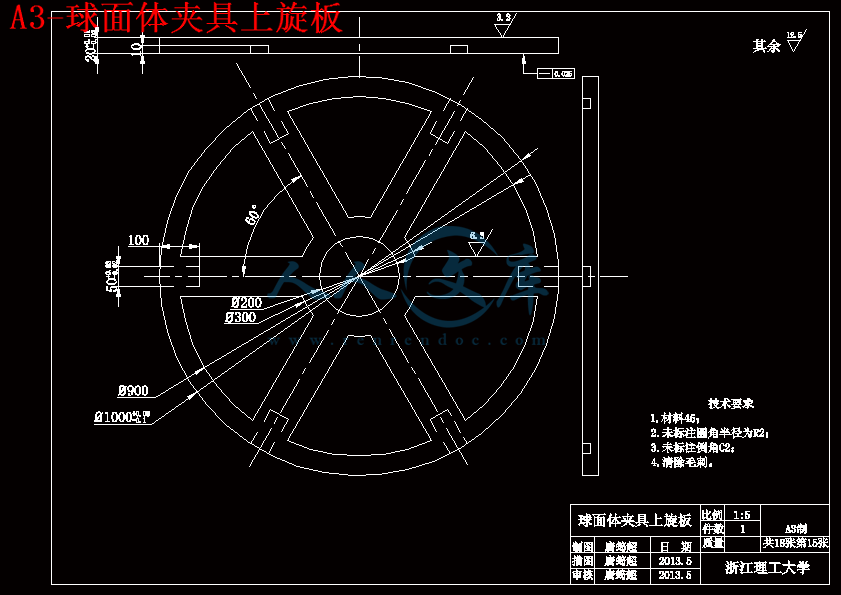
A3-球面体夹具上旋板.dwg---(点击预览)
A2-球面体夹具装配图.dwg---(点击预览)
A1-筒体夹具装配图.dwg---(点击预览)
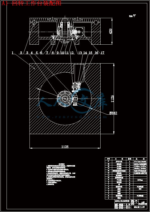
A1-回转工作台装配图.dwg---(点击预览)
pdf版本
外文翻译原文
压缩包内文档预览:
预览图 预览图 预览图 预览图 预览图
编号:445375    类型:共享资源    大小:8.46MB    格式:RAR    上传时间:2015-07-01 上传人:好资料QQ****51605 IP属地:江苏
45
积分
关 键 词:
火箭 燃料 fsw 焊接 组合 夹具 设计 全套 cad 图纸 毕业论文 答辩 通过
资源描述:

摘要

近年来,我国国用火箭燃料贮箱都是采用了搅拌摩擦焊(FSW)焊接。目前在火箭燃料贮箱的焊接过程中并没有具体统一的夹具使用,导致贮箱表面圆度与精度数值有起伏,甚至有些表面还有微型凹陷,所以设计一套火箭燃料贮箱在搅拌摩擦焊焊接过程中专用的组合夹具迫在眉睫。

火箭燃料贮箱主要由三部分组成,可以分为2个主要工件,分别是中间的薄壁筒体以及两端的半球面体。其中半球面体一般先由6块瓜瓣片形状的金属板焊接成半球面体状,再和一个端盖焊接成完整的贮箱球面盖,所以这里需要一套完整的焊接夹具。由于搅拌摩擦焊焊接机器的旋转局限性,焊接完成两个瓜瓣片之间的纵缝后,需要整个工件和夹具一起旋转60°之后才能继续焊接另外的纵缝,所以需要另外设计一台特定配置的回转工作台用来带动整个夹具和工件一起转动。设计薄壁筒体夹具时,由于用于筒体焊接的搅拌摩擦焊机器有绕中心轴旋转功能,所以不必再设计新的工作台。

设计过程:在FSW的工作原理和工件的结构基础上分析夹具需要的定位面和夹紧面;在Pro/E上绘制初步的三维模型,设计出大概的尺寸;对夹具整体的外形和尺寸进行优化,分析考虑其实用性并进行修改;通过球面体夹具的尺寸算出体积和重力;根据其他数据设计对应的回转工作台;受力分析和校核;在Pro/E上进行零件的装配;根据三维零件模型和装配模型在AutoCAD上绘制二维图;Pro/E上夹具、回转工作台、工件的配合演示。


关键字:火箭燃料贮箱;夹具;回转工作台;设计;筒体;球面体


Abstract

In recent years, friction stir welding (FSW welding) is used in China's rocket fuel tanks. At present, the use of chucking in the welding process of rocket fuel tank lack of standardization, resulting in the record of tank’s circular degree and accuracy up and down, even some surfaces emerge micro sunken. To design a suit of special combination fixture for rocket fuel tank in the friction stir welding process is extremely urgent.

Rocket fuel tank is mainly composed of three parts, can be divided into two main parts, which are thin-wall cylinder and both ends of the hemispherical work piece. Generally, the hemispherical work piece is welded by six scalloped segment metal plates at first, then weld with end cover. It requires a complete set of welding fixture. Due to the limitation of the FSW welding machine’s rotating, after welding the longitudinal seam between two scalloped segment plates, the work piece and fixture need to rotate 60 degrees to continue longitudinal seam welding. It needs designing a specific configuration rotary working-table to drive the fixture and work piece rotate together. When designing the thin-wall cylinder’s fixture, there is no need to design a new working-table because of the standard machine.

The design process: Analyze the locating surface and clamping surface of fixture’s need on the basis of FSW’s operational principle and work piece’s structure; Draw the initial 3D model in Pro/E, design outline dimensions; Optimize the whole size and shape of fixture, considering the practicability and modify; Figure out volume and gravity on the basis of the hemispherical work piece fixture’s size, design the corresponding rotary working-table on the basis of other date; Force analysis and check; Assemble parts in Pro/E; To draw 2D diagram in AutoCAD according to the 3D part model and assembly model; Show the assemble in Pro/E.


Keywords: rocket fuel tank; fixture; rotary working-table; design; cylinder; the hemispherical


目  录

摘  要

Abstract

第1章 绪论1

1.1 研究的目的及意义1

1.2 国内外研究现状3

1.2.1 薄壁筒体夹具研究现状3

1.2.2 球面体夹具研究现状4

1.3 主要研究内容6

1.3.1 筒体夹具分析与设计6

1.3.2 半球面体夹具分析与设计6

1.3.3 拟解决的主要问题7

第2章 球面体夹具设计7

2.1 机械加工工艺分析7

2.2 夹具的结构方案8

2.3 半球面体夹具装配图12

第3章 回转工作台设计13

3.1 工作台方案分析13

3.2 电机的选择14

3.3 动力参数计算15

3.4 齿轮传动设计16

3.5 涡轮蜗杆传动设计20

3.6 轴、键、轴承及联轴器的设计和选择24

3.7 轴的校核29

3.8 回转工作台装配图35

第4章 筒状体夹具设计36

4.1 机械加工工艺分析36

4.2 夹具的结构方案37

4.3 筒体夹具的装配图41

第5章 AutoCAD与Pro/E软件简介42

5.1软件简介42

5.2三维模型43

第6章 总结44

参考文献45

致  谢46

附录47


第1章 绪论

1.1 研究的目的及意义

自从1991年英国焊接研究所发明了搅拌摩擦焊技术以来,已经过去了21年,搅拌摩擦焊在这21年间为世界制造业做出了巨大的贡献,其中在航天航空,航海船泊,高速列车,交通运输这些高科技行业的表现尤其突出。2002年,在中国航空工业集团-北京航空制造工程研究所与英国焊接研究所共同签署关于搅拌摩擦焊专利技术许可、技术研发及市场开拓等领域的合作协议的基础上,中国第一家专业化的搅拌摩擦焊技术授权公司——中国搅拌摩擦焊中心即北京赛福斯特技术有限公司成立,标志着搅拌摩擦焊技术在中国市场的研发及工程应用工作的正式开启。到现在2012年我国已经成功开发了60余套搅拌摩擦焊设备,将搅拌摩擦焊技术应用于我国航空、航天、船舶、列车、汽车、电子、电力等工业领域中,创造了可观的社会经济效益,为铝、镁、铜、钛、钢等金属材料提供了完美的技术解决方法[1]。

内容简介:
Materials & Design,Vol. 18, Nos. 4r6, pp. 269273, 1997Q1998 Published by Elsevier Science LtdPrinted in Great Britain. All rights reserved0261-3069r98 $19.00q0.00()PII: S02613069 97 000629Friction stir welding for the transportationindustriesW. M. ThomasU, E. D. NicholasTWI, Abington Hall, Abington, Cambridge CB1 6AL, UKReceived 16 June 1997; accepted 17 June 1997()This paper will focus on the relatively new joining technologyfriction stir welding FSW . Like allfriction welding variants, the FSW process is carried out in the solid-phase. Generically solid-phasewelding is one of the oldest forms of metallurgical joining processes known to man. Friction stirwelding is a continuous hot shear autogenous process involving a non-consumable rotating probe ofharder material than the substrate itself. In addition, FSW produces solid-phase, low distortion, goodappearance welds at relatively low cost. Essentially, a portion of a specially shaped rotating tool isplunged between the abutting faces of the joint. Once entered into the weld, relative motion betweenthe rotating tool and the substrate generates frictional heat that creates a plasticised region around theimmersed portion of the tool. The contacting surface of the shouldered region of the tool and theworkpiece top contacting surface also generates frictional heat. The shouldered region providesadditional friction treatment to the weld region as well as preventing plasticised material beingexpelled. The tool is then translated with respect to the workpiece along the joint line, with theplasticised material coalescing behind the tool to form a solid-phase joint as the tool moves forward.Although the workpiece does heat up during FSW, the temperature does not reach the melting point.Friction stir welding can be used to join most aluminium alloys, and surface oxide presents no difficultyto the process. Trials undertaken up to the present time show that a number of light weight materialssuitable for the automotive, rail, marine, and aerospace transportation industries can be fabricated byFSW.Q 1998 Published by Elsevier Science Ltd. All rights reserved.Keywords: friction stir welding; transportation; solid phaseIntroductionRecently, a novel friction welding process for non-fer-rous materials has captured the attention of the fabri-cation industry. This relatively new process called Fric-.tion Stir Welding FSW is a solid-phase process givinggood quality butt and lap joints1 4. The FSW processhas proved to be ideal for creating high quality welds ina number of materials, including those which are ex-tremelydifficulttoweldbyconventionalfusionprocesses5.The basic principle of the process is illustrated inFigure 1. The process operates by generating frictionalheat between a rotating tool of harder material thanthe workpiece being welded, in such a manner as tothermally condition the abutting weld region in thesofter material. The tool is shaped with a larger diame-ter shoulder and a smaller diameter, specially profiledprobe. The probe first makes contact as it is plungedinto the joint region. This initial plunging friction con-tact heats a cylindrical column of metal around theprobe as well as a small region of material underneaththe probe. The depth of penetration is controlled bythe length of the probe below the shoulder of the tool.The contacting shoulder applies additional frictionalUCorrespondence to W. M. Thomas. Tel.: q44 01 223891162; fax:q44 01 223892588; e-mail: wmthomastwi.co.ukheat to the weld region and prevents highly plasticisedmaterial from being expelled during the welding opera-tion. Once the shoulder makes contact the adjacentthermally softened region takes up a frustum shapecorresponding to that of the overall tool geometry. Thethermally softened region appears much wider at thetop surface in contact with the shoulder, tapering downto the probe diameter. The combined frictional heatfrom the probe and the shoulder creates a plasticisedalmost hydrostatic condition around the immersedprobe and the contacting surface of the shoulderedregion of the workpiece top surface. Material flowsaround the tool and coalesces behind the tool as rela-tive traverse between substrate and the rotating tooltakes place. Friction stir welding can be regarded as aautogenous keyhole joining technique. The consoli-dated welds are solid-phase in nature and do not showfusion welding defects. No consumable filler material,shielding gas, or edge preparation is normally neces-sary. The distortion is significantly less than that causedby any fusion welding technique.Exploratory development work has encompassedaluminium materials from 1 to 75 mm thick.FSW welding trialsEarly exploratory development trials were carried outMaterials & Design Volume 18 Numbers 4/6 1997269Friction stir welding for the transportation industries: W. M. Thomas and E. D. NicholasFigure 1Friction stir welding techniqueFigure 2Transversemacrosectionof50mm thick6082T6aluminium alloy. Plate material welded from both sides, showingweld nugget profile and flow contourswith 6082 T6 aluminium alloy material in thicknessesranging from 1.6 to 12.7 mm. Recent trials have ex-tended the thickness range upwards to 75 mm in twopasses.Metallographic examinationA series of 50 and 75 mm thick welds in 6082 T6condition aluminium alloy, which demonstrate the pos-sibilities for the process for thick plate are shown inFigures 24. The macrosections from these welds arecharacterised by well defined weld nuggets and flowcontours, almost spherical in shape, these contours aredependant on the tool design and the welding parame-ters and process conditions used. For heat treatablematerials a well-defined heat affected zone surroundsthe weld nugget region and extends to the shoulderdiameter of the weld at the plate surface. The weldnugget itself is the region, where full dynamic re-crys-tallisation occurs that comprises of a fine equiaxedgrain structure. The measured grain size is in the orderof 24mm in diameter. Typically the parent metalchemistry is retained, without any segregation of alloy-ing elements. A hardness traverse taken from 50 mmthick test weld recorded the following values:vParent metal 100 HV2.5vWeld nugget 65 HV2.5vHAZ region 52 HV2.5FractographySamples of welded 50 mm thick 6082 T6 plate werenotched in the parent material, and the weld nuggetregion and then fractured by bending. The fracturesurfaces were examined using scanning electron mi-croscopy. Both the weld nugget and the parent materialfailed in a ductile manner by the microvoid coalescencemechanism as shown in Figure 3. However, there wasan absence of relatively large microvoids in the weldnugget sample and this may be a consequence of thebreak up of the primary constituent particles duringstir welding.Mechanical integrityFor plate thickness up to 50 mm thick, transverseMaterials & Design Volume 18 Numbers 4/6 1997270Friction stir welding for the transportation industries: W. M. Thomas and E. D. Nicholas .Figure 3Fractography comparison between weld nugget and parent metal in 50 mm thick 6082 T6 aluminium alloy plate. a Fracture in weld .nugget. Scanning microscopy of nick break bend, fracture face. b Fracture in parent metal. Scanning microscopy of nick break bend, fracturefaceFigure 4Three point bend and tensile test in 75 mm thick 6082 T6aluminium alloy FSW platesections were hammer bend tested to 1808. Whiletransverse sections taken from 75 mm thick plate werethree point bend tested as shown in Figure 4. A num-ber of tensile tests were carried out with failure typi-cally occurring in the HAZ region at 175 N mm2asshown in Figure 4. The localised reduction in specimenthickness during the tensile testing corresponds withregions of reduction in hardness.Process characteristicsExperimental research work is being carried our atTWI to evaluate a range of materials and developother FSW tools designed to improve the flow of plasti-cised material around the probe itself and to enablesubstantially thicker plates to be joined and enablerelatively high traverse rates to be achieved.Figure 5 illustrates the natural dynamic orbit inher-ently associated with every type of rotary machine. Thiseccentricity must to a greater or lesser extent be part ofthe friction stir welding process characteristics. Eccen-tricity allows hydromechanically incompressible plasti-cised material to flow more easily around the probe. Itfollows that a nominal bias off-centre or non-circularprobe will also allow plasticised material to pass aroundthe probe. Essentially it is the relationship between thegreater volume of the dynamic orbit of the probe andthe volume of the static displacement of the probe, thathelps provide a path for the flow of plasticised materialfrom the leading edge to the trailing edge of therotating tool.A number of tool geometries and tool attitude fordifferent materials have been reported in the litera-ture3,6,7. For tools positioned perpendicular to theworkpiece the leading edge of the rotation tool pro-vides a frictional preheat effect heat and subsequentthermal softening of the workpiece in front of theprobe. This preheat can be of advantage when dealingwith harder or difficult to weld materials. The greaterthe area of the shouldered region of the rotating toolmaking contact with the joint surface the greater thefrictional heat available. Increasing the diameter of theshouldered region, however, has practical limitationsand tends to produce side flash on the weld surface.Potential for the FSW process in thetransportation industryThe potential scope for FSW initially lies with joiningmaterials like aluminium, copper, copper alloys, lead,titanium, zinc etc. The applications range from thefollowing:vAirframes, fuel tanks, and thin alloy skins in theaerospaceMaterials & Design Volume 18 Numbers 4/6 1997271Friction stir welding for the transportation industries: W. M. Thomas and E. D. NicholasFigure 5Dynamic orbitplan view of rotating tool and probevSheet bodywork and engine support frames for theautomotive industryvRailway wagon and coachwork, and bulk carriertanks for the transportation industryvHulls, decks, and internal structures for high speedferries and LPG storage vessels for the shipbuildingindustryFigure 6FSW seam welding of lapped sheet with roller_track supportMaterials & Design Volume 18 Numbers 4/6 1997272Friction stir welding for the transportation industries: W. M. Thomas and E. D. NicholasThe FSW technique will move ahead with thinnersheet and foam filled sections being produced at com-paratively high traverse speeds. Developments that willenable the technique to be more flexible for thin sheetlap joining are being studied.Moing reactie support-anilFigure 6 shows a miniature caterpillar track that couldbe developed to provide local support for the rotatingtool, a moving anvil. Such a device would be able to fitinto similar joint configurations as those accessible bytraditional resistance welding techniques and tacklematerial thickness of about 1.5 mm or less. The movinganvil could be suitably interfaced with a robot for fullyautomatic seam and tack welding. The moving anvilapproach could also be considered as an alternative fora relatively large machine design. For example, insteadof a rotating head traversing along a fixed reactivesupport, the material could be transported continu-ously over carrier rollers to a fixed work station, fittedwith a moving anvil, much in the same way as adomestic sewing machine works. The moving anvilconcept may be worth considering for aerospace andautomotive applications.Concluding remarksThere is no doubt that the use of FSW will open upnew markets and new opportunities as the technologygets wider recognition as a welding process that canproduce superior welds, of improved reliability and ofincreased productivity. The FSW process i
温馨提示:
1: 本站所有资源如无特殊说明,都需要本地电脑安装OFFICE2007和PDF阅读器。图纸软件为CAD,CAXA,PROE,UG,SolidWorks等.压缩文件请下载最新的WinRAR软件解压。
2: 本站的文档不包含任何第三方提供的附件图纸等,如果需要附件,请联系上传者。文件的所有权益归上传用户所有。
3.本站RAR压缩包中若带图纸,网页内容里面会有图纸预览,若没有图纸预览就没有图纸。
4. 未经权益所有人同意不得将文件中的内容挪作商业或盈利用途。
5. 人人文库网仅提供信息存储空间,仅对用户上传内容的表现方式做保护处理,对用户上传分享的文档内容本身不做任何修改或编辑,并不能对任何下载内容负责。
6. 下载文件中如有侵权或不适当内容,请与我们联系,我们立即纠正。
7. 本站不保证下载资源的准确性、安全性和完整性, 同时也不承担用户因使用这些下载资源对自己和他人造成任何形式的伤害或损失。
提示  人人文库网所有资源均是用户自行上传分享,仅供网友学习交流,未经上传用户书面授权,请勿作他用。
关于本文
本文标题:火箭燃料贮箱FSW焊接用组合夹具设计【18张CAD图纸+毕业论文】【答辩通过】
链接地址:https://www.renrendoc.com/p-445375.html

官方联系方式

2:不支持迅雷下载,请使用浏览器下载   
3:不支持QQ浏览器下载,请用其他浏览器   
4:下载后的文档和图纸-无水印   
5:文档经过压缩,下载后原文更清晰   
关于我们 - 网站声明 - 网站地图 - 资源地图 - 友情链接 - 网站客服 - 联系我们

网站客服QQ:2881952447     

copyright@ 2020-2025  renrendoc.com 人人文库版权所有   联系电话:400-852-1180

备案号:蜀ICP备2022000484号-2       经营许可证: 川B2-20220663       公网安备川公网安备: 51019002004831号

本站为文档C2C交易模式,即用户上传的文档直接被用户下载,本站只是中间服务平台,本站所有文档下载所得的收益归上传人(含作者)所有。人人文库网仅提供信息存储空间,仅对用户上传内容的表现方式做保护处理,对上载内容本身不做任何修改或编辑。若文档所含内容侵犯了您的版权或隐私,请立即通知人人文库网,我们立即给予删除!