变速箱壳体组合机床夹具设计【12张CAD图纸+毕业答辩论文】
收藏
资源目录

压缩包内文档预览:(预览前20页/共27页)
编号:449916
类型:共享资源
大小:1.61MB
格式:RAR
上传时间:2015-07-06
上传人:好资料QQ****51605
认证信息
个人认证
孙**(实名认证)
江苏
IP属地:江苏
45
积分
- 关 键 词:
-
变速箱
壳体
组合
机床
夹具
设计
全套
cad
图纸
毕业
答辩
论文
- 资源描述:
-
变速箱壳体组合机床的夹具设计
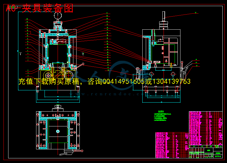
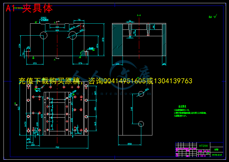
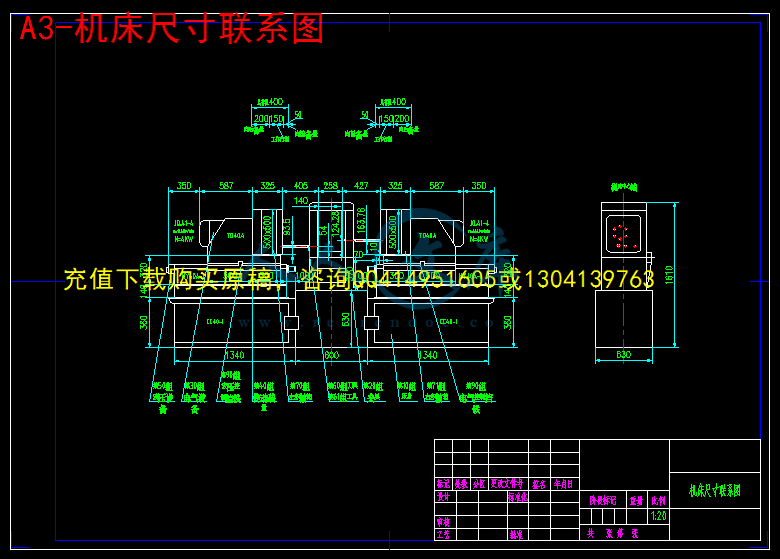
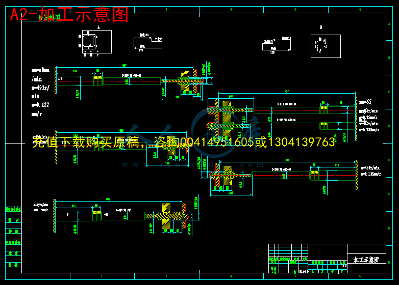
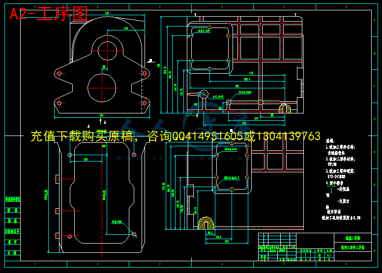
摘 要:变速箱壳体组合机床采用卧式双面加工方案。用于钻削被加工零件左侧面上的8个∅8.5的孔,1个∅11.9的孔,右侧6个∅8.5的孔,2个∅9.8的孔。主要包括总体设计和夹具设计两个部分。左侧主轴箱用来加工这9个孔,右侧主轴箱用来完成剩下的8个孔的加工,两主轴箱的中间是夹具部分。机床采用液压滑台实现刀具的进给,以保证进给速度的稳定可靠。工件选用“一面两孔”的定位方案,能够保证工件的位置精度要求,同时便于工件装夹,又有利于夹具的设计与制造。采用气压夹紧方式。为保证工件上被加工孔的位置精度,采用了导向装置。因工件批量较大,导向装置中的钻套容易磨损,所以采用了可换钻套。夹具体材料采用HT150,并在夹具体上开设排屑槽以防止切屑在定位元件工作表面上或其他装置中堆积而影响工件的正确定位和夹具的正常工作。
关键词:组合机床;总体设计;夹具
The fixture design of modular machine tool for transmission body based on 3D method
Abstract: The modular machine tool for transmission body uses the horizontal-type and two-side processing plan.It is used for drilling these holes in the work piece: eight holes with the diameter 8.5mm and depth 24mm, one hole with the diameter 11.9mm and depth 25mm on the left side,six diameter 8.5m holes and their bottom surfaces on the right surface, two diameter 9.8mm holes.The topic includes two parts, the general design and fixture design of the machine tool. The left spindle box is used for machining nine tappet holes, the right spindle box is used for machining eight holes, and a fixture is between two spindle boxes.To achieve stable and reliable feed, hydraulic pressure sliding tables are used in this machining tool.The work piece is located at the fixture through "a face two holes",which can ensure the position precision needs of the work piece and be beneficial to design the fixture.The combination machine is clamped by atmospheric pressure devices.To ensure position precision, the guiding devices are used. Replaceable guiding sleeves are chosen, because they are easy wearing in large quantities of production. The material of clamp body is HT150. Chip troughs which are in the clamp body are free of chip falling onto the working surface of positioning components or accumulating on other devices, and ensure the work piece correct positioning and the fixture normal working.
Key words: combination machine; design; fixture
目 录
1前 言1
1.1 本课题的意义1
1.2 国内发展概况1
1.3 课题由来及所需基本条件2
2组合机床总体设计3
2.1 总体方案论证3
2.1.1 加工内容及要求3
2.1.2 机床配置型式的选择3
2.1.3 定位基准的选择3
2.1.4 滑台型式的选择4
2.2 确定切削用量及选择刀具4
2.2.1 切削用量的选择4
2.2.2 计算切削力、切削扭矩及切削功率 5
2.2.3 刀具结构的选择5
2.3 总体设计—“三图一卡”6
2.3.1 被加工零件工序图6
2.3.2 加工示意图6
2.3.3 机床尺寸联系总图7
2.3.4 机床生产率计算卡9
3 组合机床夹具设计12
3.1 夹具设计的基本要求和步骤12
3.1.1 夹具设计的基本要求12
3.1.2 夹具设计的步骤12
3.2 定位方案的确定13
3.2.1 零件的工艺性分析13
3.2.2 定位方案论证13
3.2.3 误差分析13
3.2.4 校核加工精度15
3.3导向装置15
3.4 夹紧方案的确定16
3.4.1 夹紧装置的确定16
3.4.2 夹紧力的确定18
3.4.3 气缸的选择19
3.5 夹具体的设计20
3.6 夹具三维设计20
3.6.1 三维建模及三维软件介绍20
3.6.2 基于三维的夹具设计过程21
4 结论24
参 考 文 献25
致 谢26
附 件 清 单27
1 前言
1.1 本课题的意义
组合机床是由大量的通用部件和少量专用部件组成的工序集中的高效率专用机床。它能够对一种(或几种)零件进行多刀、多轴、多面、多工位加工。在组合机床上可以完成钻孔、扩孔、铰孔、镗孔、攻丝、车削、铣削、磨削及滚压等工序,生产效率高,加工精度稳定。因此,在现代化大生产中,要使零件加工具有高的生产效率,良好的加工精度、精度稳定性,好的经济性,采用组合机床加工是一个和好的选择。而如何设计一台好的组合机床就成为了关键,机床夹具是在金属切削加工中,用以准确地确定工件位置,并将其牢固地夹紧,以接受加工的工艺装备。它的主要作用是:可靠地保证工件的加工质量,提高加工效率,减轻劳动强度,充分发挥和扩大机床的工艺性能。因此,机床夹具在机械制造中占有重要的地位,这正是本课题需要解决的问题。

- 内容简介:
-
书书书文 章 编 号 : ! #$%&( $) $ #! #(收 稿 日 期 : $% #) #$)作 者 简 介 : 赵 红 星 ( !*) ) , 男 , 河 南 登 封 人 , 华 中 科 技 大 学 机 械 电 子 工 程 系 硕 士 研 究 生 , 主 要 从 事 计 算 机 辅 助 夹 具 设 计 研 究 ,( + # ,-./)0123445 4,-./6 73,。计 算 机 辅 助 夹 具 设 计 的 研 究 内 容 和 发 展 沿 革赵 红 星 , 熊 良 山( 华 中 科 技 大 学 机 械 科 学 与 工 程 学 院 , 武 汉 8 (9()摘 要 : 全 面 综 述 了 计 算 机 辅 助 夹 具 设 计 ( :;; 组 合 夹 具 ; 柔 性 夹 具 ; 夹 具 分 析 ; 夹 具 综 合中 图 分 类 号 : ?&(; ?A9*!68 8 8 8 8 文 献 标 识 码 : ;?1B CDEF.BG -HF =BIB/3J,BHD 3K :3,JEDBLM;.FBF ; ,3FE/-L K.2DELB; K/B2./B K.2DELB; K.2DELB -H-/XG.G; K.2DELB GXHD1BG.G8 引 言由 于 组 合 夹 具 的 元 件 具 有 可 重 用 性 , 能 够 适 应 多种 特 殊 加 工 情 况 的 需 要 , 因 此 , 组 合 夹 具 一 经 提 出 便 迅速 成 为 柔 性 夹 具 发 展 的 主 流 , 且 应 用 领 域 越 来 越 广 。但 是 由 于 组 合 夹 具 的 元 件 数 量 众 多 , 组 装 的 灵 活 性 大 ,采 用 传 统 的 试 错 法 组 装 对 工 人 要 求 较 高 , 且 费 时 费 力 。为 了 提 高 组 合 夹 具 组 装 的 效 率 , :;7?37/) 。 由 于 在 产 生 相 应 压 应 力和 位 移 方 面 的 能 力 , 有 限 元 方 法 已 经 应 用 在 许 多 变 形相 关 的 研 究 中 ( ?11.,A/1+) , 该 方 法 多 用 于 优 化 设 计 。( B) 基 于 规 则 或 者 基 于 特 征 的 分 析 。 基 于 特 征 的模 型 中 , 典 型 方 法 是 用 一 个 特 征 集 描 述 零 件 。 +1/6 对基 于 特 征 的 夹 具 设 计 进 行 了 深 入 研 究 。 C11 等 人 设 计出 第 一 个 基 于 规 则 的 完 全 的 夹 具 设 计 专 家 系 统 。( D) 力 学 分 析 方 法 。 广 泛 应 用 于 建 模 工 件 夹 具之 间 力 的 作 用 和 工 件 变 形 。 1A10 和 ?953 开 发 了 一 种在 工 件 夹 具 系 统 中 处 理 动 态 外 力 的 综 合 方 法 。 ?9/推 出 了 一 个 刚 度 矩 阵 公 式 用 于 顺 应 夹 具 的 准 确 高 效 建模 , 该 公 式 很 适 合 于 自 动 规 划 算 法 。#$#& 夹 具 综 合 方 法夹 具 综 合 主 要 考 虑 两 个 问 题 简 化 综 合 过 程 和削 减 计 算 ; 另 外 , 在 可 行 的 夹 具 构 形 空 间 中 的 搜 索 策 略也 很 重 要 。 #分 析 方 法 。 该 方 法 只 能 处 理 少 量 设 计 变量 。 E05+7 和 !5F-G106 提 出 了 一 种 二 维 的 “ 完 全 算 法 ” ,用 多 边 形 来 描 述 工 件 轮 廓 , 通 过 扩 展 工 件 边 将 定 位 元件 理 想 化 为 一 个 点 , 从 而 有 效 地 建 立 起 在 平 面 上 动 态约 束 工 件 的 全 部 可 行 夹 具 设 计 集 。 45/6 和 E,9 基 于 和 &+ !+ ?*:A1%, .+ /+ 67:79B 和 2+ 4+ ,7$;$C, D010 大 学 的 .+ 2+ ,+ E17FFC, 台 湾 国 立 大 学 的!+ ,+ ,5*0( 周 雍 强 ) , -G 8H9* 大 学 的 2+ ,9: 等人 ; 另 外 -+ 3+ 60, !+ 2+ E=$%, 1, /+ -+ 8:B*等 人 研 究 活 动 也 很 活 跃 M;NO。国 内 起 步 较 晚 , 但 研 究 面 广 , 且 有 后 来 居 上 态 势 。从 事 该 研 究 的 研 究 者 主 要 集 中 在 哈 尔 滨 工 业 大 学 ( 刘文 剑 、 金 天 国 等 ) 、 西 北 工 业 大 学 ( 杨 海 成 、 莫 蓉 、 唐 娜等 ) 、 南 京 航 空 航 天 大 学 ( 陈 蔚 芳 、 廖 文 和 、 黄 翔 等 ) P、北 京 理 工 大 学 ( 孙 厚 芳 、 段 晓 峰 等 ) 、 清 华 大 学 ( 融 亦鸣 、 唐 东 、 李 敏 波 等 ) 、 华 中 科 技 大 学 ( 熊 蔡 华 , 着 重 夹 具分 析 ; 李 培 根 、 蔡 力 刚 、 王 耕 耘 等 ) 、 河 北 工 业 大 学 ( 段 国林 、 林 建 平 等 ) 、 北 京 机 械 工 业 学 院 ( 朱 耀 祥 等 ) 、 北 京工 商 大 学 ( 刘 璇 、 沈 晓 红 ) ( 以 上 各 单 位 研 究 最 为 系统 ) ; 上 海 交 通 大 学 ( 林 忠 钦 、 来 新 民 , 着 重 焊 接 夹 具 ) 、东 华 大 学 ( 李 蓓 智 、 陈 冰 冰 等 , 有 夹 具 硬 件 系 统 设 计 国家 专 利 一 项 ) 、 河 海 大 学 ( 吴 玉 光 等 , 着 重 几 何 分 析 ) 、山 东 大 学 ( 徐 志 刚 等 , 着 重 体 系 结 构 ) 、 天 津 大 学 ( 王 凤岐 等 ) 、 四 川 大 学 ( 殷 国 富 ) 、 南 京 理 工 大 学 ( 张 友 良 ) 、北 京 科 技 大 学 ( 韩 蕴 秋 ) 等 。QR 发 展 趋 势 展 望预 计 计 算 机 辅 助 夹 具 设 计 的 发 展 趋 势 为 :( N) 在 制 造 系 统 中 与 其 他 ,.DDS ,.8S ,.L 和DK8、 ,-, 等 异 构 系 统 的 无 缝 集 成 ;( P) 多 智 能 体 等 先 进 .T 技 术 的 广 泛 深 入 应 用 ;,.4KU 的 广 泛 深 入 研 究 ;( V) 软 件 设 计 与 硬 件 检 测 结 合 起 来 , 实 现 物 理 上 的自 动 装 配 ;( W) 与 机 器 人 抓 取 方 面 研 究 的 结 合 。 V, M;X, Y, NP;NO 参 考 文 献 N 融 亦 鸣 , 朱 耀 祥 , 罗 振 璧 + 计 算 机 辅 助 夹 具 设 计 8 + 北 京 :机 械 工 业 出 版 社 , PZZP+ P 杨 海 成 , 廖 文 和 + 基 于 知 识 的 三 维 ,.K 技 术 及 应 用 8 +北 京 : 科 学 出 版 社 , PZZQ+ V 朱 耀 祥 , 融 亦 鸣 + 柔 性 夹 具 与 计 算 机 辅 助 夹 具 设 计 技 术 的进 展 2 + 制 造 技 术 与 机 床 , PZZZ( O) : Q O+ W 蔡 瑾 , 段 国 林 , 李 翠 玉 , 等 + 夹 具 设 计 技 术 发 展 综 述 2 + 河北 工 业 大 学 学 报 , PZZP( NZ) : VQ WZ+ Q 王 凤 岐 , 许 红 静 + 计 算 机 辅 助 夹 具 设 计 综 述 2 + 航 天 制 造技 术 , PZZV( NN) : VO WZ+ M + 8+ 01 =%$ 7$ 70*#7;*$: 1(G, =0= 7$ 001 19*$= 2 + T$1$7*$7:2*01$7: * D1*09*$ )=7195, , PZZN( VY) : POMX POYW+ X 2+ ,9:+ ,*#F01;7 H01 =%$;7 1(G 7$ 0011$= 2 + T$1$7*$7: 2*01$7: * .(7$9 87$07901$%E95$*:*%C, PZZN( NO) : XYZ XYV+ O !+ )*$%, + 37$+ ,*#F01;7 19*$%017A: H01 ;=%$ 2 + ,T)D P$ T$1$7*$7: ,*$1$9 *$ )9*$%017A:87$07901$%, .0%0= PZZV: PZ PP+ Y /+ &+ 371%1*(, .+ &0=7B+ ,*#F01;7 H01 =%$: 71(G 2 + T$+ 2+ D1*+ )=+ , NYYW( VP) : XVV XQV+ NZ .+ /$5: &0#71, 2+ !+ 3+ 405, E+ /+ &*G+ .$ 70*#7=%$ 7$ 7=#A:C * $11$9;1 #*0:71 H01 2 +,*#F01;. K=%$, PZZZ( VP) : QOV QYM+ NN 8957: !0 67$%, K7$7 8+ D:$=90+ _F#I$% H01:7C*0 $ 7 F*$;= *#7$ 2 + TLLL E17$=79*$= *$ )*A*;9= 7$ .0*#7*$, PZZN( NX) : VNP VPV+ NP 2+ + 3*0, .+ 2+ ,+ E17FFC+ ,*#F01;7 H01 =%$=C=# *1 9*#F15$=( #*0:71 H01= 2 + T$+ 2+ D1*+)=+ , PZZN( VY) : VXZV VXPQ+ NV U+ /0A17#7$7#, .+ /+ &0#71, &+ ,+ /*G+ . #0:;7%$7FF1*795 * H01 =%$ 2 + 2*01$7: * T$:%$ 87$079;01$%, PZZN( NP) : VN WP+ NW 4+ 81(C$, .+ /+ &0#71, /+ 3+ * 7$ $1$;$7A: $179( H01 =%$ =C=# 2 + ,*#F01;. K=%$, PZZV( VQ) : YWQ YQX+ NQ 2+ ,9:+ E.8T: 7$ $%17 H01 =%$ =C=# *1 F1=;#79 F71= 2 + T$1$7*$7: 2*01$7: * ,*#F01 T$%1787$07901$%, PZZW( NX) : WPN WVW+ NM -+ .#717:, 2+ 2+ )$9=, !#$% )*$%+ K(:*F#$ * 7 ;$ :#$ 7$7:C= *: *1 H01 =%$ $%1C (197*$7$ *F#=7*$ 2 + T$+ 2+ .(+ 87$0+ E95$*:+ , PZZQ( PQ) : WZY WNY+ NX 2+ .+ ,7#:*, /+ 2+ 30, 3+ !#+ /$=*1 F:79#$ *1 ;9( 7%$*= * #0:F: 70:= $ H01$% * 9*#F:7$ F71= 2 + 2*01$7: * 87$07901$% /9$9 7$ L$%$1$%, PZZQ( NPX) : MO XW+ NO + &*$%, K+ ,%:71B+ )7F (:*F#$ * 19*$%017A:7=#A:C H01= 0=$% G*1B=F79 =C$5= 7$ (=A:C 7$7:C;= 2 + .$7:= * 5 ,T)D, PZZV( QZ) : NV NM+( 编 辑 R 李 秀 敏 )W 专 题 述 评 组 合 机 床 与 自 动 化 加 工 技 术ntsInt J Adv Manuf Technol (2001) 17:4714762001 Springer-Verlag London LimitedComparative Analysis of Conventional and Non-ConventionalOptimisation Techniques for CNC Turning ProcessR. Saravanan1, P. Asokan2and M. Sachithanandam21Department of Mechanical Engineering, Shanmugha College of Engineering, Thanjavur, India; and2Department of ProductionEngineering and Management Studies, Regional Engineering College, Tirchirapalli, IndiaThis paper describes various optimisation procedures forsolving the CNC turning problem to find the optimum operatingparameters such as cutting speed and feedrate. Total pro-duction time is considered as the objective function, subject toconstraints such as cutting force, power, toolchip interfacetemperature and surface roughness of the product. Conven-tional optimisation techniques such as the Nelder Meadsimplex method and the boundary search procedure, andnon-conventional techniques such as genetic algorithms andsimulated annealing are employed in this work. An example isgiven to illustrate the working procedures for determining theoptimum operating parameters. Results are compared and theirperformances are analysed.Keywords: Boundary search procedure; Genetic algorithm;Nelder Mead simplex method; Optimisation; Simulatedannealing1. IntroductionOptimisation of operating parameters is an important step inmachining optimisation, particularly for operating CNCmachine tools. With the general use of sophisticated and high-cost CNC machines coupled with higher labour costs, optimumoperating parameters are desirable for producing the parteconomically. Although there are handbooks that provide rec-ommended cutting conditions, they do not consider the econ-omic aspect of machining and also are not suitable for CNCmachining. The operating parameters in this context are cuttingspeed, feedrate, depth of cut, etc., that do not violate any ofthe constraints that may apply to the process and satisfyobjective criteria such as minimum machining time or minimummachining cost or the combined objective function of machin-ing time and cost.Correspondence and offprint requests to: R. Saravanan, Departmentof Mechanical Engineering, Shanmugha College of Engineering, Than-javur 613402, Tamilnadu, India. E-mail: saradharaniKMachining optimisation problems have been investigated bymany researchers. Gilbert 18 presented a theoretical analysisof optimisation of the process by using two criteria: maximumproduction rate and minimum machining cost. Since the resultsobtained by using these two different criteria are always differ-ent, a maximum profit rate, which yields a compromise resulthas been used in subsequent investigations. These early studieswere, however, limited to single-pass operations without con-sideration of any constraints. Subsequent studies included vari-ous operating constraints in the optimisation models and severaltechniques have been tried for optimisation 17. In order toaccount for the stochastic nature of tool use, various probabilis-tic approaches have also been proposed. Since multipass oper-ation is often preferred to single-pass operation for economicreasons, efforts have been made to determine optimal machin-ing conditions for multipass operations 2,8,9.So far, machining optimisation problems have been investi-gated by many researchers using conventional techniques suchas geometric programming 3,4, convex programming 10,and the Nelder Mead simplex search method 1,2. Ruy Mes-quita et al. 7 have also used a conventional technique (directsearch method combination of Hook and Jeeves and randomsearch) for optimisation of multipass turning. A mathematicalmodel proposed by S. J. Chen was used in this work. It isobserved that the conventional methods are not robust because:1. The convergence to an optimal solution depends on thechosen initial solution.2. Most algorithms tend to become stuck on a suboptimal sol-ution.3. An algorithm efficient in solving one machining optimisationproblem may not be efficient in solving a different machin-ing optimisation problem.4. Computational difficulties in solving multivariable problems(more than four variables).5. Algorithms are not efficient in handling multiobjective func-tions.6. Algorithms cannot be used on a parallel machine.To overcome the above problems, non-conventional tech-niques are used in this work for solving the optimisation ofnts472 R. Saravanan et al.the turning process. In earlier work, a standard optimisationprocedure using a genetic algorithm 11 was developed tosolve different machining optimisation problems such as turn-ing, face milling and surface grinding 12. In this work,in addition to a GA, the simulated annealing technique hasbeen tried.In this work, the mathematical model proposed by Agapiou1,2 is adopted for finding the optimum operating parametersfor CNC turning operations. Total production time is consideredas the objective function, subject to constraints such as cuttingforce, power, toolchip interface temperature, and surfaceroughness of the product. Conventional optimisation techniquessuch as the Nelder Mead simplex method and the boundarysearch procedure, and non-conventional techniques such asgenetic algorithms and simulated annealing are used in thiswork. An example is given to illustrate how these proceduresare used to determine the optimum operating parameters.Results are compared and their performances are analysed.2. The Optimisation Problem 12.1 Objective FunctionThe total time required to machine a part is the sum of thetimes necessary for machining, tool changing, tool quick return,and workpiece handling:Tu= tm+ tcs(tm/T)+tR+ thThe cutting time per pass (tm) = PDL/1000 V f. Taylors toollife equation is:Vfa1doca2Ta3= KThis Eq. is valid over a region of speed and feed for whichthe tool life (T) is obtained.2.2 Operating Parameters2.2.1 FeedrateThe maximum allowable feed has a pronounced effect on boththe optimum spindle speed and production rate. Feed changeshave a more significant impact on tool life than depth of cutchanges. The system energy requirement reduces with feed,since the optimum speed becomes lower. Therefore, the largestpossible feed consistent with the allowable machine power andsurface finish is desirable, in order for a machine to be fullyused. It is often possible to obtain much higher metal removalrates without reducing tool life by increasing the feed anddecreasing the speed. In general, the maximum feed in aroughing operation is limited by the force that the cutting tool,machine tool, workpiece and fixture are able to withstand. Themaximum feed in a finish operation is limited by the surfacefinish requirement and can often be predicted to a certaindegree, based on the surface finish and tool nose radius.2.2.2 Cutting SpeedCutting speed has a greater effect on tool life than either depthof cut (or) feed. When compared with depth of cut and feed,the cutting speed has only a secondary effect on chip breaking,when it varies in the conventional speed range. There arecertain combinations of speed, feed, and depth of cut whichare preferred for easy chip removal which are mainly dependenton the type of tool and workpiece material. Charts providingthe feasible region for chip breaking as a function of feedversus depth of cut are sometimes available from the toolmanufacturers for a specific insert (or) tool, and can be incor-porated in the optimisation systems.2.3 Constraints1. Maximum and minimum permissible feed rates, cuttingspeed, and depth of cut:fmin# f # fmaxVmin# V # Vmaxdocmin# doc # docmax2. Power limitation:0.0373 V0.91f0.78doc0.75# Pmax3. Surface roughness limitations especially for finish pass:14 785 V- 1.52f1.004doc0.25# Ramax4. Temperature constraint:74.96 V0.4f0.2doc0.105#umax5. Cutting force constraint:844 V- 0.1013f0.725doc0.75# Fmax3. Conventional Optimisation Techniques3.1 Boundary Search Procedure (BSP)To start with, the depth of cut (doc) is fixed and the feedrate(f) is assumed to be at the maximum allowable limit. Thevalues of “doc” and “f” are substituted in power and tempera-ture constraint equations and the corresponding cutting speeds(Vpand Vt) are calculated. Further the obtained values “f” and“V” are accepted or modified according to constraint violationand objective function minimisation using the bounding phaseand interval halving method the flowchart of which is givenin Fig. 1.3.2 Nelder Mead Simplex Method (NMS) 13In this method, three points are used in the initial simplex. Ateach iteration, the worst point (Xh) in the simplex is found. Atfirst, the centroid (Xo) of all but the worst point is determined.Thereafter, the worst point in the simplex is reflected aboutthe centroid and the new point (Xr) is found. If the constraintsare not violated at this point the reflection is considered tohave taken the simplex to a good region in the search space.Thus, an expansion (Xe) along the direction from the centroidto the reflected point is performed. On the other hand, if theconstraints are violated at the reflected point, a contraction(Xcont) in the direction from the centroid is made. The procedurentsConventional and Non-Conventional Optimisation Techniques 473Fig. 1. Flowchart of “boundary search procedure”.Table 1. By boundary search procedure.Number doc Vf TU1 2.0 119.77 0.762 2.842 2.5 112.95 0.762 2.933 3.0 114.02 0.680 3.114 3.5 118.28 0.582 3.345 4.0 122.13 0.509 3.596 4.5 124.45 0.452 3.847 5.0 125.10 0.406 4.10is repeated until the termination criteria are met. The followingequations are used in the method:Xo= (Xl+ Xg)/2Xr= 2Xo- XhXe= (1 + g) Xo- g XhXcont= (1 + b) Xo- b XhTable 2. By Nelder Mead simplex method.Number doc Vf TU1 2.0 118.32 0.750 2.872 2.5 113.13 0.738 2.973 3.0 108.67 0.660 3.154 3.5 117.50 0.546 3.445 4.0 126.25 0.473 3.696 4.5 125.42 0.463 3.847 5.0 126.35 0.420 4.10Where, g = expansion coefficient (2.0); b = contraction coef-ficient (0.5).The flowchart is given in Fig. 2.4. Non-Conventional OptimisationTechniques4.1 Genetic Algorithms (GA) 1417GAs form a class of adaptive heuristics based on principlesderived from the dynamics of natural population genetics. Thesearching process simulates the natural evaluation of biologicalcreatures and turns out to be an intelligent exploitation of arandom search. A candidate solution (chromosomes) is rep-resented by an appropriate sequence of numbers. In manyapplications the chromosome is simply a binary string of 0and 1. The quality is the fitness function which evaluates achromosome with respect to the objective function of theoptimisation problem. A selected population of solution(chromosome) initially evolves by employing mechanismsmodelled after those currently believed to apply in genetics.Generally, the GA mechanism consists of three fundamentaloperations: reproduction, crossover and mutation. Reproductionis the random selection of copies of solutions from the popu-lation according to their fitness value, to create one or moreoffspring. Crossover defines how the selected chromosomes(parents) are recombined to create new structures (offspring)for possible inclusion in the population. Mutation is a randommodification of a randomly selected chromosome. Its functionis to guarantee the possibility of exploring the space of sol-utions for any initial population and to permit the escape froma zone of local minimum. Generally, the decision of thepossible inclusion of crossover/mutation offspring is governedby an appropriate filtering system. Both crossover and mutationoccur at every cycle, according to an assigned probability. Theaim of the three operations is to produce a sequence ofpopulations that, on average, tends to improve.4.1.1 The Optimisation Procedure Using GAStep 1. Choose a coding to represent problem parameters, aselection operator, a crossover operator and a mutation operator.Choose a population size n, crossover probability pc, andmutation probability pm. Initialise a random population ofstrings of size l. Choose a maximum allowable generationnumber tmax. Set t = 0.nts474 R. Saravanan et al.Fig. 2. Flowchart of “Nelder Mead simplex method”.Step 2. Evaluate each string in the population.Step 3.Ift . tmax(or) other termination criteria is satisfied,terminate.Step 4. Perform reproduction on the population.Step 5. Perform crossover on random pairs of strings.Step 6. Perform bitwise mutation.Step 7. Evaluate strings in the new population. Set t = t+1and go to step 3.End4.1.2 GA ParametersSample size = 20Crossover probability = 0.8Mutation probability = 0.05Number of generations = 1004.2 Simulated Annealing (SA) 16The simulated annealing procedure simulates the annealingprocess to achieve the minimum function value in a minimis-ation problem. The slow cooling phenomenon of the annealingprocess is simulated by controlling a temperature-like parameterintroduced using the concept of the Boltzmann probabilitydistribution. According to the Boltzmann probability distri-bution, a system at thermal equilibrium at a temperature T hasits energy distributed probabilistically according to P(E) =exponent of (- DE/kT), where k is the Boltzmann constant. Thisexpression suggests that a system at a high temperature hasan almost uniform probability of being at any energy state,but at a low temperature it has a small probability of beingat a high energy state. Therefore, by controlling the temperatureT and assuming that the search process follows the Boltzmannprobability distribution, the convergence of an algorithm canbe controlled.ntsConventional and Non-Conventional Optimisation Techniques 475Table 3. By genetic algorithm.Number doc Vf TU1 2.0 118.91 0.764 2.852 2.5 114.15 0.644 3.123 3.0 114.49 0.665 3.134 3.5 120.61 0.531 3.465 4.0 106.16 0.565 3.516 4.5 104.80 0.454 3.967 5.0 110.58 0.435 4.14Table 4. By simulated annealing.Number doc Vf TU1 2.0 120.39 0.753 2.852 2.5 112.57 0.761 2.933 3.0 116.68 0.648 3.154 3.5 118.21 0.582 3.345 4.0 122.05 0.507 3.596 4.5 125.41 0.448 3.857 5.0 126.28 0.400 4.12The above procedure can be used in the function minimis-ation of the total production time in the CNC turning optimis-ation problem. The algorithm begins with an initial point x1(V1, f1) and a high temperature T. A second point x2(V2, f2)is created at random in the vicinity of the initial point and thedifference in the function values (DE) at these two points iscalculated. If the second point has a smaller function value,the point is accepted; otherwise the point is accepted with aprobability exp (- DE/T). This completes one iteration of thesimulated annealing procedure. In the next generation, anotherpoint is created at random in the neighbourhood of the currentpoint and the Metropolis algorithm is used to accept or rejectthe point. In order to simulate the thermal equilibrium at everytemperature, a number of points are usually tested at a parti-cular temperature, before reducing the temperature. The algor-ithm is terminated when a sufficiently small temperature isobtained or a small enough change in function values is found.4.2.1 The Optimisation Procedure Using SAStep 1. Choose an initial point x1(V1, f1), a terminationcriteria e.Table 5. The total production time obtained from different techniques and percentage deviation of time with reference to BSP methods.NMS GA SABSPNumber doc TUTU% dev TU% dev TU% dev1 2.0 2.84 2.87 +1.0 2.85 +0.4 2.85 +0.42 2.5 2.93 2.97 +1.0 3.12 +1.0 2.93 03 3.0 3.11 3.15 +1.0 3.13 +1.0 3.15 +1.04 3.5 3.34 3.44 +3.0 3.46 +3.0 3.34 05 4.0 3.59 3.69 +3.0 3.51 +3.0 3.59 06 4.5 3.84 3.88 +1.0 3.96 +1.0 3.85 +0.37 5.0 4.10 4.23 +3.0 4.14 +3.0 4.12 +0.5Set T a sufficiently high value, number of iterations to beperformed at a particular temperature n, and set t = 0.Step 2. Calculate a neighbouring point x2. Usually, a randompoint in the neighbourhood is created.Step 3.IfDE = E(x2) - E(x1) , 0, set t = t +1;Else create a random number r in the range (0,1). Ifr # exp (- DE/T) set t = t+1;Else go to step 2.Step 4. If ux2- x1u ,eand T is small, terminate.Else if (t mod n) = 0 then lower T according to acooling schedule.Goto step 2;Else goto step 2.5. Data of the Problem 1L = 203 mm D = 152 mm Vmin= 30 m min- 1Vmax= 200 m min- 1fmin= 0.254 mm rev- 1fmax= 0.762 mm rev- 1Ramax(rough) = 50 mm Ramax(finish) = 20 mm Pmax= 5kWFmax= 900 N umax= 500 Cdocmin(r)= 2.0 mmdocmax(r)= 5.0 mm docmin(f)= 0.6 mm docmax(f)= 1.5 mma1 = 0.29 a2 = 0.35 a3 = 0.25K = 193.3 tcs= 0.5 min/edge tR= 0.13 min/passth= 1.5 min/piece Co= Rs3.50/min Ct= Rs17.50/edge6. Optimisation ResultsTables 1 to 4 show the operating parameters such as cuttingspeed, feed rate and total production time obtained usingconventional and non-conventional techniques.Table 5 shows the total production time obtained fromdifferent techniques and percentage deviation of time withreference to BSP method.7. ConclusionIn this work, optimisation of the CNC turning process issolved using conventional and non-conventional optimisationtechniques. An example is given to illustrate the workingprocedures of these techniques in solving the above problem.It is observed that a boundary search procedure is able to findthe exact answer, but it is not flexible enough to include morents476 R. Saravanan et al.variables and equations. The results obtained by simulatedannealing are comparable with the boundary search procedureand the flexibility of the method needs further investigation.The Nelder Mead simplex method deviates from the boundarysearch method by 1%3%, but with simple modificati
- 温馨提示:
1: 本站所有资源如无特殊说明,都需要本地电脑安装OFFICE2007和PDF阅读器。图纸软件为CAD,CAXA,PROE,UG,SolidWorks等.压缩文件请下载最新的WinRAR软件解压。
2: 本站的文档不包含任何第三方提供的附件图纸等,如果需要附件,请联系上传者。文件的所有权益归上传用户所有。
3.本站RAR压缩包中若带图纸,网页内容里面会有图纸预览,若没有图纸预览就没有图纸。
4. 未经权益所有人同意不得将文件中的内容挪作商业或盈利用途。
5. 人人文库网仅提供信息存储空间,仅对用户上传内容的表现方式做保护处理,对用户上传分享的文档内容本身不做任何修改或编辑,并不能对任何下载内容负责。
6. 下载文件中如有侵权或不适当内容,请与我们联系,我们立即纠正。
7. 本站不保证下载资源的准确性、安全性和完整性, 同时也不承担用户因使用这些下载资源对自己和他人造成任何形式的伤害或损失。

人人文库网所有资源均是用户自行上传分享,仅供网友学习交流,未经上传用户书面授权,请勿作他用。
 川公网安备: 51019002004831号