钻床主轴进给机构改造——变速机构设计【7张CAD图纸+毕业答辩论文】
收藏
资源目录

压缩包内文档预览:
编号:451606
类型:共享资源
大小:1.37MB
格式:RAR
上传时间:2015-07-07
上传人:好资料QQ****51605
认证信息
个人认证
孙**(实名认证)
江苏
IP属地:江苏
45
积分
- 关 键 词:
-
钻床
主轴
进给
机构
改造
变速
设计
全套
cad
图纸
毕业
答辩
论文
- 资源描述:
-
摘 要
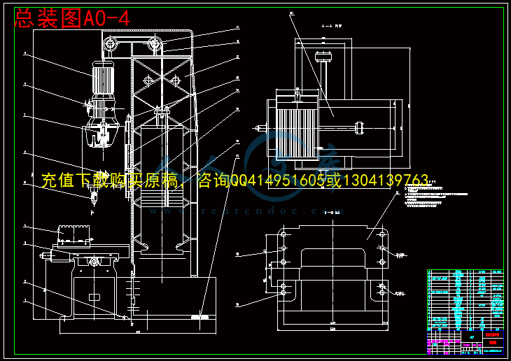
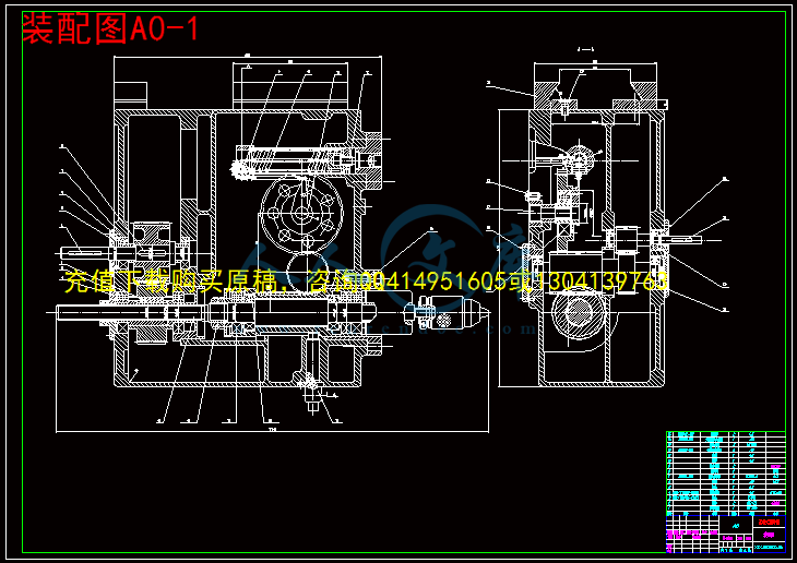
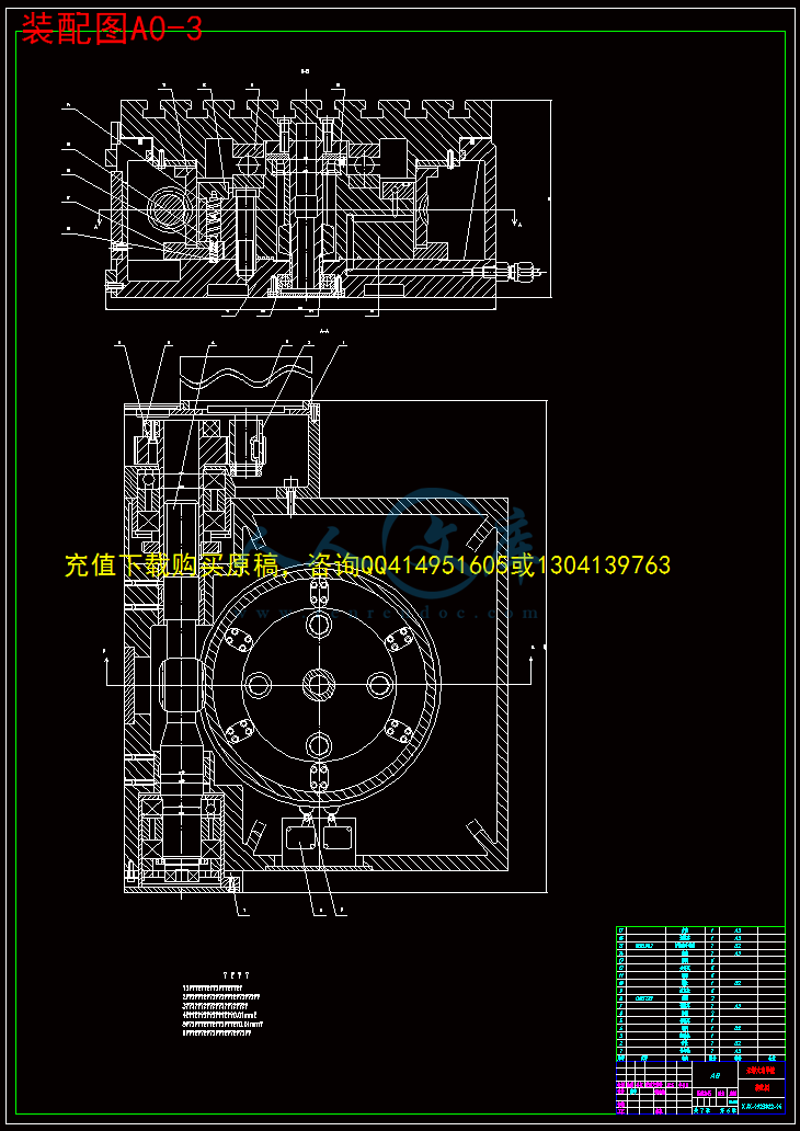
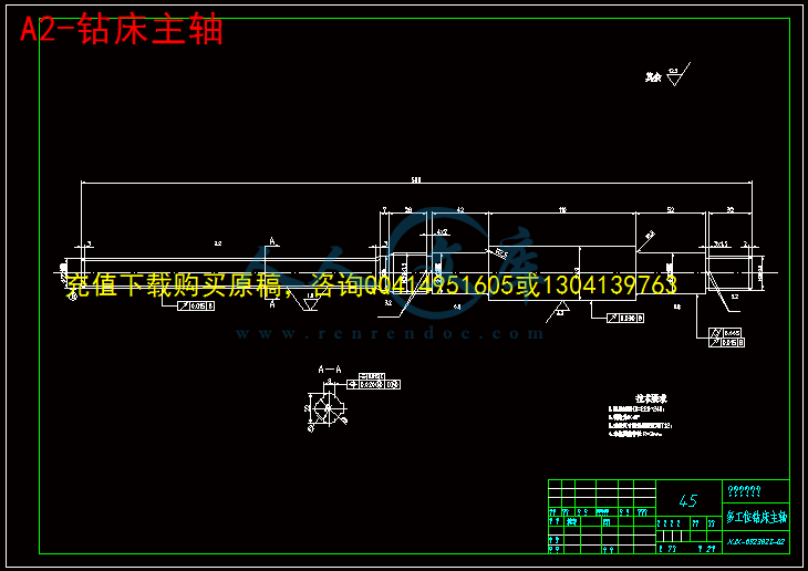
随着先进制造技术的发展和进步,数控加工已成为机加工过程中的一种主流技术。这一技术的运用提高了机加工过程中工作效率和加工精度。数控多工位钻床就是提高钻削加工精度和效率的一种很好的机加工工具。本文对数控多工位钻床进行了设计,采用了普通车床设计的步骤和方法,综合考虑数控机床的特点。从切削力入手确定主轴及电机,到整个机床的结构设计和机床的控制。最后到对机床初始化程序设计。本文完成数控多工位钻床的资料收集与国、内外现状的调查比较,提出较为可行的方案;完成机床的机械结构设计计算与电气控制系统设计,初步完成控制系统的软硬件设计。本设计是关于将普通钻床改造为多工位加工钻床的结构设计。普通钻床为单轴机床,且工件安装后需要进行反复调整,工件上有相互位置要求的各表面间的位置精度就会受到很多因素的影响,通过设计改造成快速主轴、移动工作台和具有一定回转精度的能实现多工位加工的钻床后,能大大地缩短加工时间,提高生产效率。因此本设计主要从钻床的主轴箱设计、移动工作台设计及工作台的回转设计几个方面,对普通钻床进行一定的结构改进,实现多工位加工,以符合现代机械加工的要求。
关键词:多工位钻床;生产效率;主轴箱
Abstract
With the manufacturing development, numerical control manufacturing has become one of the major advanced technologies. efficiency and accuracy has been improved in application of the technology. Numerical control auto-drilling machine is a kind of the new machine tools that can improve the machining accuracy and efficiency. The paner has designed for Numerical control auto-drilling machine, using design method of the ordinary lathe, and considering the characteristic of the numerical control machine tools synthetically. cutting force has been calculated, the structural and the control system has been designed. Finally, the software routine has been explored.This paner has finished completed a investigation of internal and external of current situation for numerical control multistage-drilling machine, and compared it, put forward a feasible scheme; completed the mechanical structural design an calculated and designed the electric control system, and finished the software and hardware of the control system tentatively.The design is about reconstructing the ordinary drill to carry out multiple position drill. The ordinary drill is a single drill. The machining accuracy of the work-piece will be affected by the mount. Because the exact position of work-piece will be affected by the adjustment. It will promote its productive efficiency, shorten its processing time through the design of the rapid spindle, moving and evolution worktable. Hereby, the keystone of this design paper is how to design the rapid spindle, moving and evolution worktable.
Key words: multiple drill; productive efficiency; multiple spindle heads
目录
摘 要III
AbstractIV
目录V
1 绪论1
1.1 钻床的工艺范围1
1.2 钻床的类型1
1.2.1 台式钻床1
1.2.2 立式钻床1
1.2.3 摇臂钻床2
1.3 钻削加工的特点2
1.3.1 多轴加工的特点3
1.3.1 多工位加工的特点3
1.4 论文研究的内容及意义3
1.5 本文所做的工作3
2 机械传动方案确定4
2.1 设计内容分析4
2.2机械传动方案的选择4
2.2.1 总体传动方案选择4
2.2.2 总体传动方案确定5
3 主轴传动部件设计7
3.1 切削力的计算7
3.1.1 机床工况要求7
3.1.2 切削力和切削扭矩的计算7
3.2 主轴齿轮传动方案确定9
3.2.1 设定齿轮传动方案9
3.2.2 主轴传动设计和计算10
4 工作台纵向进给机构的设计18
4.1 工作台纵向进给负载分析及计算18
4.1.1 摩擦阻力计算18
4.1.2 等效转动惯量计算18
4.1.3 丝杠摩擦阻力矩的计算19
4.1.4 等效负载转矩的计算19
4.1.5 起动惯性阻力矩的计算19
4.1.6 步进电机输出轴总的负载转矩的计算19
4.2 纵向进给步进电机选择19
4.3 纵向进给滚珠丝杠的选择与校核19
4.3.1 承载能力的校核19
4.3.2 压杆稳定性验算20
4.3.3 刚度验算20
4.4 滑动导轨的结构设计21
4.4.1 移动导轨的分析21
4.4.2 移动导轨的预选21
4.4.3 移动导轨的验算22
4.5 纵向进给轴承的选择25
5 横向进给运动机构的设计25
5.1 横向进给负载分析及计算25
5.1.1 摩擦阻力的计算25
5.1.2 等效转动惯量计算25
5.1.3 丝杠摩擦阻力矩的计算26
5.1.4 等效负载转矩的计算26
5.1.5 起动惯性阻力矩的计算27
5.1.6 步进电机输出轴总的负载转矩的计算27
5.2 横向进给步进电机选择27
5.3 横向进给滚珠丝杠的选择与校核27
5.3.1 承载能力的校核27
5.3.2 压杆稳定性验算27
5.3.3 刚度验算28
5.4 滑动导轨的结构设计28
5.4.1 移动导轨的分析28
5.4.2 移动导轨的预选29
5.4.3 移动导轨的验算29
5.5 横向进给机构轴承的选择31
6 回转工作台的结构设计31
6.1 蜗轮蜗杆的设计计算31
6.1.1 初选[d1/a]值31
6.1.2 中心距计算31
6.2 传动基本尺寸的确定32
6.3 传动机构的校核计算32
6.3.1 蜗轮按齿面接触疲劳强度验算32
6.3.2 轮齿弯曲疲劳强度验算34
6.3.3 蜗杆轴绕度验算34
6.3.4 温度计算35
6.3.5 润滑油粘度和润滑方法35
6.3.6 花键的选择35
结论与展望36
毕业设计小结37
致 谢38
参考文献39
1 绪论
随着时代的发展,作为现代科学技术发展的重要标志之一的金属切削机床得到了更多的研究和发展,而随着在机加工中广泛投入使用这种机床,更是促进了传统的机械加工行业的高速发展。由于多工位加工机床极大地提高了加工精度、生产率和自动化程度,受到了生产商的广泛欢迎。而多工位机床则因其一次装夹能进行多工位的加工。在某种程度上,更是大大的提高了机加工的加工效率,很适合工件的批量生产。


- 内容简介:
-
编号 无锡 太湖学院 毕业设计(论文) 相关资料 题目: 钻床主轴进给机构改造 变速机构设计 信机 系 机 械 工 程 及 自 动 化 专业 学 号: 0923822 学生姓名: 沈 宇 指导教师: 韩邦华 (职称 : 副教授 ) (职称: ) 2013年 5月 25日 nts nts 目 录 一、毕业设计(论文)开题报告 二、毕业设计(论文)外文资料翻译及原文 三、学生 “毕业论文(论文)计划、进度、检查及落实表 ” 四、实习鉴定表 nts nts无锡 太湖学院 毕业设计(论文) 开题报告 题目: 钻床主轴进给机构改造 变速机构设计 信机 系 机 械 工 程 及 自 动 化 专业 学 号: 0923822 学生姓名: 沈 宇 指导教师: 韩邦华 (职称: 副教授 ) (职称: ) 2012年 11月 25日 nts 课题来源 无锡某企业生产实际 科学依据 (包括课题的科学意义;国内外研究概况、水平和发展趋势;应用前景等) 本课题 为基于多工位加工的普通钻床结构设计 ,由于生产纲领为大批大量生产,故将涉及大批量加工的工艺规程设计、 专用机床 和专用夹具设计等, 尤其随着工业的发展, 快速进给及多工位加工 更是引人注目。 实现多工位 加工不但可以扩大加工范围,而且在提高精度的基础上还能大大地提高工效 , 完成该课题可对我们大学期间所学知识进行一次全面的专业训练,可以培养我们掌握如何运用过去所学知识去解决生产中实际问题的方法,增强从事本专业实际工作所必需的基本能力和开发研究能力,可以提高我们的专业素质,为今后走上工作岗位打下一个良好的基础。 nts研究内容 本课题的专题是 基于多工位加工的普通钻床改造设计 。 钻 床被广泛用于大、中批量零件如:汽车、拖拉 机 、摩托车等行业的汽缸体、变速箱壳体 、杠杆拨叉 等加工领域。 为了适应大 批量生产,专用多工位钻削 加工具有较大的优势,它按照 孔 的分布位置 ,通过 PLC 控制可 实 现 一次 装夹 , 多工位加工, 从而保证了 各孔间 的位置及尺寸精度。对于在大批量生产模式下的 金属切削加工 应保证快速并且稳定,必需设计出高效率的 专用加工设备 ,并要做到最合理,这样才能保证加工质量和提高生产率。 拟采取的研究方法、技术路线、实验方案及可行性分析 在毕业实习调研以及查阅有关资料的基础上,结合 钻削加工的特点 ,设计出基于多工位加工的快速主轴、移动工作台及回转工作台,实现在普通钻床一次装夹多工位加工的高效机床, 经反 复对各方案对比分析,采用以专用机床与专用夹具为主组成生产流水线,提高 机械加工效率以节省劳动时间。通过实验分析回转加工的特点,改进专用 机床 的结构设计,并 采用动作迅速并安全可靠的机构。 nts研究计划及预期成果 通过现场调研、模拟、建模、实验和机器调试, 根据加工对象的具体工艺要求来合理地 改进多工位加工钻床的结构 形式, 提高 机械加工效率以节省劳动时间,并 降低工人的劳动强度和 企业的 生产成本。 特色或创新之处 适用于本厂的某 加工 生产线的优化设计, 力求在不影响加工的前提下最 大限度的减少成本 , 并 降低工人的劳动强度和生产成本。 已具备的条件和尚需解决的问题 针对实际 机械加工 过程中存在的 工时定额 问题,综合所学的机械理论设计 、 方法 及工艺装备 , 提高机械零件加工的精度及工艺成本,进而提升学生开发和创新机械产品的能力 。 nts指导教师意见 指导教师签名: 年 月 日 教研室(学科组、研究所)意 见 教研室主任签名: 年 月 日 系意见 主管领导签名: 年 月 日 ntsThe Features and Development History and Application of Hydraulic and Pneumatic Transmutation 1.The advantages of hydraulic transmission 1) A hydraulic system can produce higher power than electrical equipment under the same volume . The hydraulic equipment system has smaller volume , light , high power consistency and compact configuration at a given power . The volume and weight of a hydraulic motor are about 12% of an electric motor . 2) Hydraulic equipment has a good working stability . It is because of light , less inertia , quick response : the hydraulic equipment can realize celerity start-up , brake and frequent change in motion direction . 3) The hydraulic transmission can reach a wide range of speed regulation (with the range of 1:2000), and the speed can also be regulated during the work processing . 4) The hydraulic transmission can easily realize automation and the pressure , flow rate and the flow direction can be regulated and controlled . If we combine it with electric , electron or pneumatic control systems , a more complex transmission system with remote control can be realized . 5) The hydraulic system can protect from over-load easily , which cannot be done by electricity or machine equipment . 6) Because of standardization , series , and all-purpose application ; the hydraulic system is easier in design , fabrication and application . 7) The hydraulic system is easier than machine equipment in doing line motion . 2.The shortages of hydraulic transmission 1) Leak . Oil leaks are inevitable because of the loss in fluid flow resistance . So more energy loss exists in a hydraulic transmission . 2) Working temperature . The working temperature has strong effect on the working property of a hydraulic system because of the viscosity-temperature character of hydraulic oil . It is suitable for working in a proper temperature . 3) Cost . The cost is high because of the needs in high precision fabricate for hydraulic elements . 4) It is difficult to find the reasons of fault . 3. The advantages of pneumatic transmission . 1) The air can be obtained and expelled from the atmosphere . It cannot bring pollution to the environment . 2) It is of low viscosity and lower pressure loss in pipes . The pressure air is convenient for convergence supply and remote transportation . 3) It is of low working pressure ( usually 0.3-0.8MP a ). Avowers material and fabricate precision is required for the pneumatic transmission elements . 4) The pneumatic transmission has a simple servicing .The air pipe is not easy to be jammed . 5) Safety . The pneumatic system can protect from over-load easily . nts4. The shortcomes of pneumatic transmission 1) It is because of air compressibility . The working stabilities for pneumatic transmission system are poorer than those of hydraulic transmission system . 2) Because of lower working pressure and small size in configuration , the push force of pneumatic transmission is usually very lower . 3) Lower transmission efficiency . To sum up , the strong-points of hydraulic and pneumatic transmission have taken the main advantages , and the shortages have been overcome and improved by technical renovation . The fundamental law underlying the whole science of hydraulics was discovered by Blasie Pascal ,a French physicist ,in the seventeenth century .But it was not until the end of the 18 century that man found ways to make the snugly fitting parts required in hydraulic systems and other modern equipment .Since then progress has been rapid . Hydraulic transmission has been experiencing the process as below . The 17th and 18th centuries were a productive period in the development of hydraulic theory . Torricelli studied fluid motion in the early 17th century .Late in that century ,Sir Isaac Newton conducted studies on viscosity and the resistance of submerged bodies in a moving fluid .The key achievements of the period occurred in the middle of the 18th century when Daniel Bullion developed the theory of transmission of energy in fluid streams and Blas Pascal ,at about the same time ,established the principle of hydrostatic pressure transmission . This principle was first used in the latter part of the 18th century .The first hydraulic pressure machine was manufactured by England in the late 18th century .The fundamentals of fluid theory were established by the above work and refinements were added by Navier who derived the mathematics of motion in liquids including equations for fluid flow with friction .This was early in the 19th century .It was followed by the work of Stokes ,who independently discovered the same equations and further extended the work of Navicert . Recently hydraulic and pneumatic pressure transmission technology has been developed with a large scale petrolic industry in the 19th century ,and the barbette displace was the first one successful using hydraulic equipment ,and then hydraulic machine tool .In World War I many new machines based on the principles of hydraulics had been used .The great automotive industy introduced hydraulic brakes in the early thirties and hydraulic transmissions in the late thirties .The tractor industry began using hydraulics in 1940 to increase the flexibility and utility of farm equipment .In World War II because of the demand transmission and control equipments in fast reaction ,precision action and high output powers boosted development in hydraulic theology .After the War ,the hydraulic development turned into civil industry ,such as machine tool ,engineering ,metallurgy ,plastic machine ,farm machine ,vehicle and watercraft .In more recent years ,the role of leadership in hydraulic power application has been taken over largely by some of the large earthmoving and construction equipment manufacturers .The total power involved is often greater than that required in even the largest aircraft systems . ntsWith the development of higher automation of hydraulic machines and increasing use of hydraulic and pneumatic elements ,the scaled elements and integrated hydraulic system with miniaturization is inevitable .Especially in recent years hydraulic and pneumatic transmission is combined closely with the sensor and micro-electricity technology .It has been emerging amounts of new valves such as hydraulic-electricity proportional valves ,digital valves ,hydraulic and electro-hydraulic servo cylinders and the integrative elements ,which will lead the hydraulic and pneumatic technology to the development of higher pressure ,higher speed ,larger power ,lower energy wastage and noise ,longevity and high integration .Computer aided design (CAD ) and test (CAT ) and practical control technology used in hydraulic and pneumatic system will be the trend .Nowadays the application of hydraulic transmission system has become one of the important indications of industry level for a country .In developed countries ,95%of engineering machine ,90%of numerical control center and more than 95%of automation assembly lines use the hydraulic transmission system . nts液压与气压传动的特点及发展应用概况 1. 液压传动有以下优点 1)在同等体积下,液压装置毕电气装置产生更高的动力。再同等功率下,液压装置体积小,重量轻,功率密度大,结构紧凑。液压马达的体积和重量只有同等功率电动机的 12%左右。 2)液压装置工作比较平稳。由于重量轻、惯性小、反应快,液压装置易于实现快速启动、制动和频繁的换向。 3)液压装置能在大范围内实现无级调速(调速范围可达 2000),它还可以在运行过程中进行调速。 4)液压传动易于自动化,它对液体压力、流量或流动方向易于进行调节或控制。当将液压控制和电气控制、 电子控制或气动控制结合起来使用时,整个传动装置能实现复杂的顺序动作,也能方便的实现远程控制。 5)液压装置易于实现过载保护,这是电气传动装置和机械传动装置无法办到的。 6)由于液压元件已经实现了标准化、系列化和通用化,液压系统的设计、制造和使用都比较方便。 7)用液压传动实现直线运动远比用机械传动简单。 2.液压传动的缺点 1)由于流体流动的阻力损失和泄露是不可避免的,所以液压传动在工作过程中常有较多的能量损失。 2)工作性能易受温度变化的影响,因此不宜在很高或很低的温度下工作。 3)为了减少泄漏,液压元件 的制造精度要求较高,因而价格较贵。 4)液压传动出现故障时不易找出原因。 3.气压传动的优点 1)空气可以从大气中取得,同时,用过的空气可直接排放到大气中去,处理方便,万一空气管路有泄漏,除引起部分功率损失外,不知产生不利于工作的严重影响,也不会污染环境。 2)空气粘度很小,在管道中的压力损失较小,因此压缩空气便于集中供应和远距离输送。 3)因压缩空气的工作压力较低(一般为 0.30.8Mpa),因此,对气动元件的材料和制造精度上的要求较低。 4)气动系统维护简单,管道不易堵塞。 5)使用安全,并且便于实现 过载保护。 4.气压传动的缺点 1)由于空气具有可压缩的特性,因此运动速度的平稳性不如液压传动。 2)因为工作压力较低和结构尺寸不宜过大,因而气压传动装置的总推力一般不可能很大。 3)传动效率低。 总的说来,液压与气压传动的优点是主要的,而它们的缺点通过技术进步和多年的不懈
- 温馨提示:
1: 本站所有资源如无特殊说明,都需要本地电脑安装OFFICE2007和PDF阅读器。图纸软件为CAD,CAXA,PROE,UG,SolidWorks等.压缩文件请下载最新的WinRAR软件解压。
2: 本站的文档不包含任何第三方提供的附件图纸等,如果需要附件,请联系上传者。文件的所有权益归上传用户所有。
3.本站RAR压缩包中若带图纸,网页内容里面会有图纸预览,若没有图纸预览就没有图纸。
4. 未经权益所有人同意不得将文件中的内容挪作商业或盈利用途。
5. 人人文库网仅提供信息存储空间,仅对用户上传内容的表现方式做保护处理,对用户上传分享的文档内容本身不做任何修改或编辑,并不能对任何下载内容负责。
6. 下载文件中如有侵权或不适当内容,请与我们联系,我们立即纠正。
7. 本站不保证下载资源的准确性、安全性和完整性, 同时也不承担用户因使用这些下载资源对自己和他人造成任何形式的伤害或损失。

人人文库网所有资源均是用户自行上传分享,仅供网友学习交流,未经上传用户书面授权,请勿作他用。
 川公网安备: 51019002004831号