说明书.doc

五自由度的曲轴搬运上线机械手的设计【优秀含8张CAD图纸+UG三维建模+工业机械手全套课程毕业设计】

收藏

资源目录
跳过导航链接。
五自由度的曲轴搬运上线机械手的设计【优秀含8张CAD图纸+UG三维建模+工业机械手全套课程毕业设计】.rar
说明书.doc---(点击预览)
目 录.doc---(点击预览)
摘要.doc---(点击预览)
开题报告.doc---(点击预览)
封面.doc---(点击预览)
实习报告.doc---(点击预览)
外文文献翻译.doc---(点击预览)
任务书.doc---(点击预览)
UGsanweijianmo
0.prt
01.prt
010.prt
011.prt
012.prt
013.prt
014.prt
015.prt
016.prt
017.prt
018.prt
02.prt
020.prt
021.prt
022.prt
023.prt
024.prt
025.prt
026.prt
027.prt
028.prt
029.prt
03.prt
030.prt
031.prt
032.prt
033.prt
034.prt
035.prt
036.prt
037.prt
038.prt
039.prt
04.prt
040.prt
041.prt
042.prt
043.prt
044.prt
045.prt
046.prt
047.prt
048.prt
049.prt
05.prt
050.prt
051.prt
052.prt
053.prt
054.prt
055.prt
056.prt
057.prt
058.prt
059.prt
06.prt
060.prt
061.prt
07.prt
09.prt
1.prt
A3活塞零件图.dwg
后盖.dwg
回转缸体.dwg
手腕.dwg
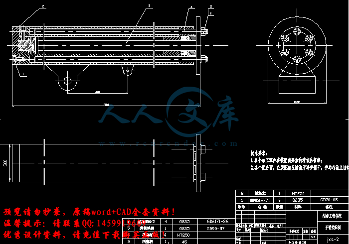
手臂机构图.fdwg.dwg
机械手总装图.dwg
活塞杆零件图.dwg
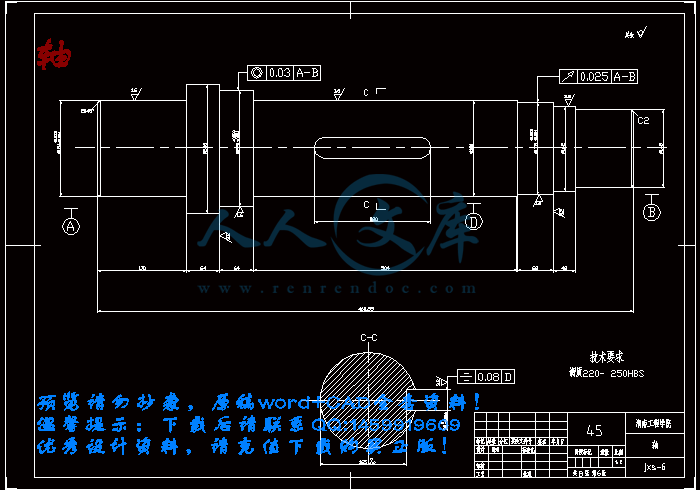
轴.dwg
压缩包内文档预览:(预览前20页/共52页)
预览图 预览图 预览图 预览图 预览图 预览图 预览图 预览图 预览图 预览图 预览图 预览图 预览图 预览图 预览图 预览图 预览图 预览图 预览图 预览图
编号:455878    类型:共享资源    大小:3.83MB    格式:RAR    上传时间:2015-07-11 上传人:QQ14****9609 IP属地:陕西
50
积分
关 键 词:
五自由度 曲轴搬运 上线机械手 机械设计 毕业设计 五自由度的曲轴搬运上线机械手的设计 工业机械手全套课程毕业设计
资源描述:

曲轴搬运上线机械手设计

多关节式工业机械手的设计

五自由度的曲轴搬运上线机械手的设计【优秀含8张CAD图纸+工业机械手全套课程毕业设计】

【带任务书+开题报告+实习报告+外文翻译】【57页@正文26100字】【详情如下】【需要咨询购买全套设计请加QQ1459919609】                                    

A3活塞零件图.dwg

UG图

后盖.dwg

回转缸体.dwg

手腕.dwg

手臂机构图.fdwg.dwg

机械手总装图.dwg

轴.dwg

(A3)活塞杆零件图.fdwg.dwg

任务书.doc

外文文献翻译.doc

实习报告.doc

封面.doc

开题报告.doc

摘要.doc

目 录.doc

说明书.doc

目 录

摘要………………………………………………………………………………Ⅰ

Abstract……………………………………………………………………………Ⅱ

第1章 引言…………………………………………………………………………1

      1.1 工业机械手的发展史…………………………………………………1

      1.2工业机械手的用途………………………………………………2

      1.3 工业机械手的发展趋势………………………………………………3

      1.4 机械手的组成…………………………………………………………4

      1.5 应有机械手的意义……………………………………………………………6

第2章 总体设计方案及系统组成………………………………………………………7

      2.1液压机械手的组成及各部分关系概述………………………………7

      2.2 液压力机械手的设计分析……………………………………………7

         2.2.1设计要求…………………………………………………………7

         2.2.2 总体设计任务分析………………………………………………8

         2.2.3 总体方案拟定……………………………………………………8

         2.2.4 自动搬运机械手的设计方案论证………………………………9

第3章 机身设计……………………………………………………………………12

      3.1机身设计要点…………………………………………………………12

      3.2驱动力计算……………………………………………………………12

第4 章 手臂设计…………………………………………………………………14

      4.1 手臂设计要点…………………………………………………………14

         4.1.1应使手臂刚度大、重量轻………………………………………14

         4.1.2应使手臂运动速度 、惯性小…………………………………15

         4.1.3手臂动作应灵活………………………………………………16

4.1.4应使手臂传动准确、导向性好…………………………………16

         4.1.5 位置精度要求高………………………………………………16

      4.2手臂机构的选择与设计………………………………………………17

         4.2.1手臂直线运动机构……………………………………………17

              4.2.1.1直线运动机构…………………………………………17

              4.2.1.2导向装置………………………………………………17

              4.2.1.3手臂驱动力计算………………………………………19

              4.2.1.4手臂伸缩油伸缩油缸的设计计算……………………19

         4.2.2手臂回转运动机构……………………………………………19

              4.2.2.1只含回转缸一种缸体的机身机构……………………19

              4.2.2.2回转缸置于升降之下的机身结构……………………19

               4.2.2.3臂部回转运动驱动力矩的计算……………………19

          4.2.3手臂俯仰运动机构……………………………………………20

               4.2.3.1驱动力矩的计算……………………………………20

               4.2.3.2俯仰摆动缸驱动力计算……………………………21

第 5章 手腕设计………………………………………………………………22

      5.1手腕回转结构…………………………………………………………22

      5.2 手腕驱动力矩的计算…………………………………………………22

第 6 章 手部的设计计算 …………………………………………………………24

      6.1手指夹紧缸驱动力计算………………………………………………24

第 7章 主要液压元件的设计计算 ………………………………………………26

      7.1 液压缸的计算…………………………………………………………26

      7.2 油泵的选择论证………………………………………………………26

         7.2.1 油泵的工作压力计算…………………………………………27

         7.2.2 油泵流量计算…………………………………………………27

         7.2.3 油泵电机功率计算……………………………………………27

第 8章 液压缸的设计计算………………………………………………… 29                        

     8.1  液压缸内径的设计计算……………………………………………29

        8.1.1 液压缸主要尺寸的计算…………………………………………29

        8.1.2 液压缸筒壁厚的设计计算………………………………………31

     8.2 液压缸主要零件的结构材料及技术要求……………………………32

     8.3 液压缸活塞缸的校核…………………………………………………33

        8.3.1 活塞缸的强度校核………………………………………………33

        8.3.2 活塞缸的弯曲稳定性校核………………………………………34

第 9章 液压系统的设计…………………………………………………………36

      9.1 液压系统设计…………………………………………………………36

      9.2 拟定液压系统原理图…………………………………………………36

         9.2.1 基本回路的选择………………………………………………36

         9.2.2液压阀的选择…………………………………………………37

      9.3机械手液压系统图及特点……………………………………………38

      9.4 液压系统电磁铁动作表………………………………………………39

      9.5 液压系统的特点………………………………………………………41

第 10章 控制系统的设计…………………………………………………………42

      10.1 PLC的工作原理………………………………………………………42

      10.2控制面板设计………………………………………………………42

      10.3硬件选择……………………………………………………………43

      10.3公用程序编写………………………………………………………42

      10.4手动程序和自动程序………………………………………………43

     10.5自动控制程序的输出电路……………………………………………44

小结…………………………………………………………………………………47

参考文献……………………………………………………………………………48

致谢…………………………………………………………………………………49

附录 …………………………………………………………………………………50

摘要

本文将设计一台五自由度的曲轴搬运上线机械手,目的是为了提高曲轴加工过程中的劳动生产率,实现机械加工的自动化。根据机械手的工作要求和结构特点,进行了机械手的总体设计,确定了机械手的外形尺寸和工作空间,拟定了机械手各关节的总体传动方案,采用可编程控制器( PLC) 对其液压驱动装置进行顺序控制,实现了系统的自动化。该设计提高了加工的自动化程度,全部机械设计采用了等强度、可靠性设计方法,初步达到了高效低成本生产加工的目标。

关键词:机械手;曲轴; 顺序控制

ABSTRACT

In this paper, the design of a crankshaft of the five degrees of freedom manipulator handling on-line in order to improve the process of the crankshaft labor productivity, to achieve the automation of machining. According to the work manipulator and structural characteristics of the requirements for the design of the mechanical hand, determine the size of the robot and work space, the development of a manipulator of the overall transmission of the joint program, the use of programmable logic controller (PLC) of its hydraulic-driven sequential control devices to achieve automation of the system. The design increased the degree of automation for processing all the mechanical design, such as intensity of use, reliability design method, the initial reach of a highly efficient production and processing of low-cost objectives.

Keywords: Manipulator; Crankshaft; sequence control

第1章  引 言

机械手(mechanical hand)也被称为自动手(auto hand)。工业机械手(简称机械手)是近代自动控制领域中出现的一项新技术,并已渐成为现代机械制造系统中的一个重要组成部分。这种新技术发展很快,逐渐形成一门新兴的学科——机械手工程。

机械手之所以迅速发展还因为它的积极作用日益为人们所认识:其一、它能部分的代替人工操作;其二、它能按照生产工艺的要求,遵循一定的程序、时间和位置来完成工作的传送和装卸;起三、它能操作必要的机具进行焊接和装配。从而大大地改善工人的劳动条件,显著提高劳动生产率,加快实现工业生产机械化和自动化的步伐。因而,受到各先进工业国家的重视,投入大量的人力物力加以研究和应用

工业机械手是在自动线上搬运物料的一种自动化装置。其工作对象是将物料从生产线上转运到下道工序或存放位置。 主要完成以下几个动作:下降一旋转一抓取并夹持物料一旋转一上升一松开并放置物料。

1.1 工业机械手的发展史

早在三国时代,诸葛亮发明的木牛流马即是古代中国人的智能结晶。随着近代的工业革命,机器产业的不断发展成为近代工业的主要支柱。由于科学幻想所系的“永动机”、太空探险以及梦想解决人的机能所无法达致境界的求新意念,推动科学家想研究创造出种种能够代替人的机械。上世纪六、七十年代的自动化机器、无人操纵的飞行器等等,即是此产业发展链条上的一个大胆的尝试与突破。

机械手首先是从美国开始研制的。1958年美国联合控制公司研制出第一台机械手。它的结构是:机体上安装一回转长臂,端部装有电磁铁的工件抓放机构,控制系统是示教型的。

参 考 文 献

[1] 天津大学工业机械手编写组.工业机械手设计基础.天津:天津科学技术出版社,1980.8.

[2] 梁利华.液压传动与电液伺服系统.哈尔滨:哈尔滨工程大学出版社,2005.

[3] 李慧勇,张竺英.水下机械手运动学逆解的一种优化解法[J].机床与液压,2003.

[4] 杜志俊.工业机器人的应用及发展趋势.机械工业出版社,2002.

[5] 张效祖.工业机器人的现状与发展趋势.世界制造技术与装备市场,2004.

[6] 朱浩翔.工业机器人及其应用.装备机械,2003.

[7] 杨化书,曲新峰.工业机器人技术的应用及发展黄河水利职业技术学院.学报,2004.

[8] 刘庆潭.材料力学.北京:机械工业出版社,2003.2.

[9] 孔庆华,刘传绍.极限配合与测量技术基础.上海:同济大学出版社,2002.2.

[10] 濮良贵,纪名刚.机械设计.北京:高等教育出版社,2001.6.

[11] 方昌林.液压、气压传动与控制.北京:机械工业出版社,2000.

[12] 何存兴.液压传动与气压传动.武汉:华中科技大学出版社,2000.

[13] 章宏甲,黄谊,王积伟.液压与气压传动.北京:机械工业出版社,2000.

[14] 张铁,谢存禧.机器人学.广州:华南理工大学出版社,2001.4.

[15] 张福学.机器人技术及其应用.北京:电子工业出版社,1999.

[16] 朱世强,王宣银.机器人技术及其应用.杭州:浙江大学出版社,2006.

[17] 王知行,刘延荣.机械原理.北京:高等教育出版社,2000.

[18] 钟约先.机械系统计算机控制.北京:清华大学出版社,2001.4.

[19] 宗光华 等.机器人的创意设计与实践.北京:北京航空航天大学出版社,2004.2.

[20] 大连组合机床研究所.组合机床设计.北京:机械工业出版社,1978.2.


内容简介:
湖南工程学院 毕业设计(论文)任务书 设计(论文)题目: 曲轴搬运上线机械手设计 姓名 学院 机械工程 专业 机械设计 班级 机设 0784 学号 200713090420 指导老师 谭立新 职称 教授 教研室主任 一、 基本任务及要求: 任务 1.总体方案设计 (平面、三维、爆炸图) 要求 1.图纸折 合 A0不少于 3.0 张 2.主要技术参数确定 2.说明书论文少于 1.5万字 3.搬运线机械手设计 3.独立完成 4. 主要零部件设计 5. 控制系统设计 6. 应用相关合适软件分析研究 二、 进度安排及完成时间: 第 1 周:课题熟悉 资料查阅 第 10 周: 平面、三维、爆炸图 第 2 周:开题报告 文献综述 第 11 周: 控制系统 系统设计 第 3 周:拟定总体方案 第 12 周: 分析研究 第 4 周:总装图草案、初定主要结构 第 13 周: 分析研究及 部分程序 第 5 周:机动 第 14 周: 说明书(论 文)撰写 第 6 周:毕业实习 及实习报告 第 15 周: 审核 第 7 周: 平面、三维、爆炸图 第 16 周: 答辩、成绩评定 第 8 周: 平面、三维、爆炸图 第 9 周: 平面、三维、爆炸图 nts COMBINATION OF ROBOT CONTROL AND ASSEMBLY PLANNING FOR A PRECISION MANIPULATOOR Abstract This paper researches how to realize the automatic assembly operation on a two-finger precision manipulator. A multi-layer assembly support system is proposed. At the task-planning layer, based on the computer-aided design (CAD) model, the assembly sequence is first generated, and the information necessary for skill decomposition is also derived. Then, the assembly sequence is decomposed into robot skills at the skill-decomposition layer. These generated skills are managed and executed at the robot control layer. Experimental results show the feasibility and efficiency of the proposed system. Keywords Manipulator Assembly planning Skill decomposition Automated assembly 1 Introduction Owing to the micro-electro-mechanical systems (MEMS) techniques, many products are becoming very small and complex, such as microphones, micro-optical components, and microfluidic biomedical devices, which creates increasing needs for technologies and systems for the automated precision assembly of miniature parts. Many efforts aiming at semi-automated or automated assembly have been focused on microassembly technologies. However, microassembly techniques of high flexibility, efficiency, and reliability still open to further research. Thispaper researches how to realize the automatic assembly operation on a two-finger micromanipulator. A multi-layer assembly support system is proposed. Automatic assembly is a complex problem which may involve many different issues, such as task planning, assembly sequences generation, execution, and control, etc. It can be simply divided into two phases; the assembly planning and the robot control. At the assembly-planning phase, the information necessary for assembly operations, such as the assembly sequence, is generated. At the robot control phase, the robot is driven based on the information generated at the assembly-planning phase, and the assembly operations are conducted. Skill primitives can work as the interface of assembly planning to robot control. Several robot systems based on skill primitives have been reported. The basic idea behind these systems is the robot programming. Robot movements are specified as skill primitives, based on which the assembly task is manually coded into programs. With the programs, the robot is controlled to fulfill assembly tasks automatically. nts A skill-based micromanipulation system has been developed in the authors lab, and it can realize many micromanipulation operations. In the system, the assembly task is manually discomposed into skill sequences and compiled into a file. After importing the file into the system, the system can automatically execute the assembly task. This paper attempts to explore a user-friendly, and at the same time easy, sequence-generation method, to relieve the burden of manually programming the skill sequence. It is an effective method to determine the assembly sequence from geometric computer-aided design (CAD) models. Many approaches have been proposed. This paper applies a simple approach to generate the assembly sequence. It is not involved with the low-level data structure of the CAD model, and can be realized with the application programming interface (API) functions that many commercial CAD software packages provide. In the proposed approach, a relations graph among different components is first constructed by analyzing the assembly model, and then, possible sequences are searched, based onthe graph. According to certain criterion, the optimal sequence is finally obtained. To decompose the assembly sequence into robot skill sequences, some works have been reported. In Nnaji et al.s work, the assembly task commands are expanded to more detailed commands, which can be seen as robot skills, according to a predefined format. The decomposition approach of Mosemann and Wahl is based on the analysis of hyperarcs of AND/OR graphs representing the automatically generated assembly plans. This paper proposes a method to guide the skill decomposition. The assembly processes of parts are grouped into different phases, and parts are at different states. Specific workflows push forward parts from one state to another state. Each workflow is associated with a skill generator. According to the different start state and target state of the workflow, the skill generator creates a series of skills that can promote the part to its target state. The hierarchy of the system proposed here ,the assembly information on how to assemble a product is transferred to the robot through multiple layers. The top layer is for the assembly-task planning. The information needed for the task planning and skill generation are extracted from the CAD model and are saved in the database. Based on the CAD model, the assembly task sequences are generated. At the skill-decomposition layer, tasks are decomposed into skill sequences. The generated skills are managed and executed at the robot control layer. 2 Task planning Skills are not used directly at the assembly-planning phase. Instead, the concept of a task is nts used. A task can fulfill a series of assembly operations, for example, from locating a part, through moving the part, to fixing it with another part. In other words, one task includes many functions that may be fulfilled by several different skills. A task is defined as: T =( Base Part; Assembly Part; Operation) Base_Part and Assembly_Part are two parts that are assembled together. Base_Part is fixed on the worktable, while Assembly_Part is handled by robots end-effector and assembled onto the Base_Part. Operation describes how the Assembly_Part is assembled with the Base_Part; Operation Insertion_T, screw_T, align_T,. The structure of microparts is usually uncomplicated, and they can be modeled by the constructive solid geometry (CSG) method. Currently, many commercial CAD software packages can support 3D CSG modeling. The assembly model is represented as an object that consists of two parts with certain assembly relations that define how the parts are to be assembled. In the CAD model, the relations are defined by geometric constraints. The geometric information cannot be used directly to guide the assembly operationwe have to derive the information necessary for assembly operations from the CAD model. Through searching the assembly tree and geometric relations (mates relations) defined in the assemblys CAD model, we can generate a relation graph among parts, for example, In the graph, the nodes represent the parts. If nodes are connected, it means that there are assembly relations among these connected nodes (parts). 2.1 Mating direction In CSG, the relations of two parts, geometric constraints, are finally represented as relations between planes and lines, such as collinear, coplanar, tangential, perpendicular, etc. For example, a shaft is assembled in a hole. The assembly relations between the two parts may consist of such two constraints as collinear between the centerline of shaft Lc_shaft and the centerline of hole Lc_hole and coplanar between the plane P_Shaft and the plane P_Hole. The mating direction is a key issue for an assembly operation. This paper applies the following approach to compute the possible mating direction based on the geometric constraints (the shaft-in-hole operation of Fig. 3 is taken as an example): 1. For a part in the relation graph, calculate its remaining degrees of freedom,also called degrees of separation, of each geometric constraint. For the coplanar constraint, the remaining degrees of freedom are zRotyxR ,1 . For the collinear constraint, the remaining degrees of freedom are zRotzR ,2 . 1R and 2R can also be represented as 1,0,0,0,1,11 R and 1,0,0,1,0,02 R . Here, 1 means that there is a degree of nts separation between the two parts. 1,0,0,00,021 , RR, and so, the degree of freedom around the z axis will be ignored in the following steps. In the case that there is a loop in the relation graph, such as parts Part 5, Part 6, and Part 7 in Fig. 2, the loop has to be broken before the mating direction is calculated. Under the assumption that all parts in the CAD model are fully constrained and not over-constrained, the following simple approach is adopted. For the part t in the loop, calculate the number of 1s in iniiti RRRN . .21 ; where ikR is the remaining degrees of freedom of constraint k by part i. For example, in Fig. 2, given that the number of 1s in7,5 partpartUand 7,6 partpartUis larger than 6,5 partpartUand 5,6 partpartU, respectively, then it can be regarded that the position of Part 7 is determined by constraints with both Part 5 and Part 6, while Part 5 and Part 6 can be fully constrained by constraints between Part 5 and Part 6.We can unite Part 5 and Part 6 as one node in the relation graph, also called a composite node, as shown in Fig. 2b. The composite node will be regarded as a single part, but it is obvious that the composite node implies an assembly sequence. 2. Calculate mating directions for all nodes in the relation graph. Again, beginning at the state that the shaft and the hole are assembled, separate the part in one degree of separation by a certain distance (larger than the maximum tolerance), and then check if interference occurs. Separation in both x axis and y axis of R1 causes the interference between the shaft and the hole. Separation in the +z direction raises no interference. Then, select the +z direction as the mating direction, which is represented as a vector M measured in the coordinate system of the assembly. It should be noted that, in some cases, there may be several possible mating directions for a part. The condition for assembly operation in the mating direction to be ended should be given. When contact occurs between parts in the mating direction at the assembled state, which can be checked simply with geometric constraints, the end condition is measured by force sensory information, whereas position information is used as an end condition. 3. Calculate the grasping position. In this paper, parts are handled and manipulated with two separate probes, which will be discussed in the Sect. 4, and planes or edges are considered for grasping. In the case that there are several mating directions, the grasping planes are selected as G1G2.Gi, where Gi is possible grasping plane/edge set for the ith mating direction when the part is at its free state. For example, in Fig. 4, the pair planes P1/P1, P2/P2, and P3/P3 can serve as possible grasping planes, and then the grasping planes are 1P 1 / P2P 2 / P,1P 1 / P3P 3 / P,1P 1 / P3P 3 / P,2P 2 / P,1P 1 / P3_2_1_ d i rm a t i n gd i rm a t i n gd i rm a t i n g GGG The approaching direction of the end-effector is selected as the normal vector of the nts grasping planes. It is obvious that not all points on the grasping plane can be grasped. The following method is used to determine the grasping area. The end-effector, which is modeled as a cuboid, is first added in the CAD model, with the constraint of coplanar or tangential with the grasping plane. Beginning at the edge that is far away from the Base_Part in the mating direction, move the end-effector in the mating direction along the grasping plane until the end-effector is fully in contact with the part, the grasping plane is fully in contact with the end-effector, or a collision occurs. Record the edge and the distance, both of which are measured in the parts coordinate system. 4. Separate gradually the two parts along the mating direction, while checking interference in the other degrees of separation, until no interference occurs in all of the other degrees of separation. There is obviously a separation distance that assures interference not to occur in every degree of separation. It is called the safe length in that direction. This length is used for the collision-free path calculation, which will be discussed in the following section. 2.2 Assembly sequence Some criteria can be used to search the optimal assembly sequence, such as the mechanical stability of subassemblies, the degree of parallel execution, types of fixtures, etc. But for microassembly, we should pay more attention to one of its most important features, the limited workspace, when selecting the assembly sequence. Microassembly operations are usually conducted and monitored under microscopy, and the workspace for microassembly is very small. The assembly sequence brings much influence on the assembly efficiency. For example, a simple assembly with three parts. In sequence a, part A is first fixed onto part B. In the case that part C cannot be mounted in the workspace at the same time with component AB because of the small workspace, in order to assemble part C with AB, component AB has to be unmounted from the workspace. Then, component C is transported and fixed into the workspace. After that, component AB is transported back into the workspace again. In sequence b, there is no need to unmount any part. Sequence a is obviously inefficient and may cause much uncertainty. In other words, the greater the number of times of unmounting components required by an assembly sequence, the more inefficient the assembly sequence. In this paper, due to the small -workspace feature of microassembly, the number of times necessary for the mounting of parts is selected as the search criteria to find the assembly sequence that has a few a number of times for the mounting of parts as possible. This paper proposes the following approach to search the assembly sequence. The relation graph of the assembly is used to search the optimal assembly sequence. Heuristic approaches are adopted in order to reduce the search times: nts 1. Check nodes connected with more than two nodes. If the mating directions of its connected nodes are different, mark them as inactive nodes, whereas mark the same mating directions as active mating direction. 2. Select a node that is not an inactive node. Mark the current node as the base node (part). The first base part is fixed on the workspace with the mating direction upside (this is done in the CAD model). Compare the size (e.g., weight or volume) of the base part with its connected parts, which can be done easily by reading the bill of materials (BOM) of the assembly. If the base part is much smaller, then mark it as an inactive node. 3. Select a node connected with the base node as an assembly node (part). Check the mating direction if the base node needs to be unmounted from the workspace. If needed, update a variable, say mount+. Reposition the component (note that there may be not only the base part in the workspace; some other parts may have been assembled with the base part) in the workspace so that the mating direction is kept upside. 4. In the CAD model, move the assembly part to the base part in the possible mating direction, while checking if interference (collision) occurs. If interference occurs, mark the base node as an inactive node and go to step 2, whereas select the Operation type according to parts geometric features. In this step, an Obstacle Box is also computed. The box, which is modeled as a cuboid, includes all parts in the workspace. It is used to calculate the collision-free path to move the assembly part, which will be introduced in the following section. The Obstacle Box is described by a position vector and its width, height, and length. 5. Record the assembly sequence with the Operation type, the mating direction, and the grasping position. 6. If all nodes have been searched, then mark the first base node as an inactive node and go to step 2. If not, select a node connected with the assembly node. Mark it as an assembly node, and the assembly node is updated as a base node. Check if there is one of the mating directions of the assembly node that is same as the mating direction of the former assembly node. If there is, use the former mating direction in the following steps. Go to step 3. After searching the entire graph, we may have several assembly sequences. Comparing the values of mount, the more efficient one can be selected. If not even one sequence is returned, then users may have to select one manually. If there are N nodes in the relation graph of Fig. 2b, all of which are not classed as inactive node, and each node may have M mating directions, then it needs MN computations to find all assembly sequences. But because, usually, one part only has one mating direction, and there are some inactive nodes, the computation should be less than MN. It should be noted that, in the above computation, several coordinate systems are involved, such as the coordinates of the assembly sequence, the coordinates of the base part, and the nts coordinates of the assembly. The relations among the coordinates are represented by a 44 transformation matrix, which is calculated based on the assembly CAD model when creating the relations graph. These matrixes are stored with all of the related parts in the database. They are also used in skill decomposition. 3 Skill decomposition and execution 3.1 Definition of skill primitive Skill primitives are the interface between the assembly planning and robot control. There have been some definitions on skill primitives. The basic difference among these definitions is the skill s complexity and functions that one skill can fulfill. From the point of view of assembly planning, it is obviously better that one skill can fulfill more functions. However, the control of a skill with many functions may become complicated. In the paper, two separate probes, rather than a single probe or parallel jaw gripper, are used to manipulate the part. Even for the grasp operation, the control process is not easy. In addition, for exam
温馨提示:
1: 本站所有资源如无特殊说明,都需要本地电脑安装OFFICE2007和PDF阅读器。图纸软件为CAD,CAXA,PROE,UG,SolidWorks等.压缩文件请下载最新的WinRAR软件解压。
2: 本站的文档不包含任何第三方提供的附件图纸等,如果需要附件,请联系上传者。文件的所有权益归上传用户所有。
3.本站RAR压缩包中若带图纸,网页内容里面会有图纸预览,若没有图纸预览就没有图纸。
4. 未经权益所有人同意不得将文件中的内容挪作商业或盈利用途。
5. 人人文库网仅提供信息存储空间,仅对用户上传内容的表现方式做保护处理,对用户上传分享的文档内容本身不做任何修改或编辑,并不能对任何下载内容负责。
6. 下载文件中如有侵权或不适当内容,请与我们联系,我们立即纠正。
7. 本站不保证下载资源的准确性、安全性和完整性, 同时也不承担用户因使用这些下载资源对自己和他人造成任何形式的伤害或损失。
提示  人人文库网所有资源均是用户自行上传分享,仅供网友学习交流,未经上传用户书面授权,请勿作他用。
关于本文
本文标题:五自由度的曲轴搬运上线机械手的设计【优秀含8张CAD图纸+UG三维建模+工业机械手全套课程毕业设计】
链接地址:https://www.renrendoc.com/p-455878.html

官方联系方式

2:不支持迅雷下载,请使用浏览器下载   
3:不支持QQ浏览器下载,请用其他浏览器   
4:下载后的文档和图纸-无水印   
5:文档经过压缩,下载后原文更清晰   
关于我们 - 网站声明 - 网站地图 - 资源地图 - 友情链接 - 网站客服 - 联系我们

网站客服QQ:2881952447     

copyright@ 2020-2025  renrendoc.com 人人文库版权所有   联系电话:400-852-1180

备案号:蜀ICP备2022000484号-2       经营许可证: 川B2-20220663       公网安备川公网安备: 51019002004831号

本站为文档C2C交易模式,即用户上传的文档直接被用户下载,本站只是中间服务平台,本站所有文档下载所得的收益归上传人(含作者)所有。人人文库网仅提供信息存储空间,仅对用户上传内容的表现方式做保护处理,对上载内容本身不做任何修改或编辑。若文档所含内容侵犯了您的版权或隐私,请立即通知人人文库网,我们立即给予删除!