设计说明书.doc

升降平台的液压系统设计【优秀含6张CAD图纸+液压全套课程毕业设计】

收藏

压缩包内文档预览:(预览前20页/共22页)
预览图 预览图 预览图 预览图 预览图 预览图 预览图 预览图 预览图 预览图 预览图 预览图 预览图 预览图 预览图 预览图 预览图 预览图 预览图 预览图
编号:457974    类型:共享资源    大小:359.57KB    格式:RAR    上传时间:2015-07-18 上传人:QQ14****9609 IP属地:陕西
50
积分
关 键 词:
升降平台 液压系统 毕业设计 升降平台的液压系统设计 液压全套课程毕业设计
资源描述:

升降平台的液压系统设计【优秀含6张CAD图纸+液压全套课程毕业设计】

【带任务书+开题报告+中期检查表+文献综述+外文翻译】【22页@正文7900字】【详情如下】【需要咨询购买全套设计请加QQ1459919609】

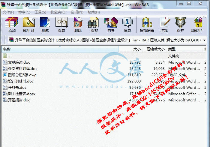
任务书.doc

图纸6张.dwg

外文资料翻译.doc

开题报告.doc

文献综述.doc

期中检查表.docx

设计说明书.doc

任务书

毕业设计(论文)题目升降平台的液压系统设计

毕业设计(论文)主要内容和要求:

本次毕业设计对象是液压升降平台的液压系统,这套装置主要用于举升重物。其动作主要是由两个双作用液压缸推动“X”型架,带动上板来实现的。该液压升降平台主要由两个部分组成:机械部分和液压部分,其中机械部分主要由上板架、下板架、内连杆和外连杆四部分组成。

设计参数:

举升高度为1米,举升重量为1吨。

要求:

利用所学的理论知识,学会如何解决实际问题,设计出规范化、标准化的图纸。

毕业设计(论文)主要参考资料:

《机械设计》、《液压传动》、《机械制图》、《材料力学》、《机械设计手册》、《互换性与测量技术基础》

毕业设计(论文)应完成的主要工作:

液压缸装配图一张(0号图纸);

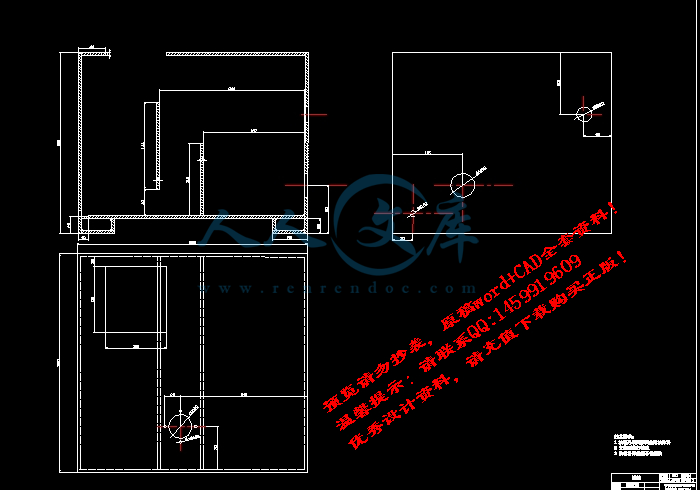
油箱图一张(0号图纸);

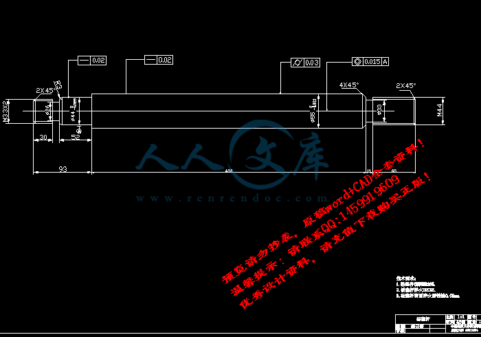
液压缸活塞杆图一张(1号图纸);

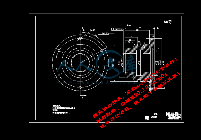
液压缸缸盖图一张(2号图纸);

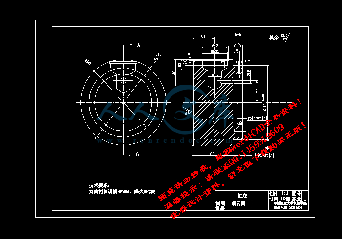
液压缸缸底图一张(3号图纸);

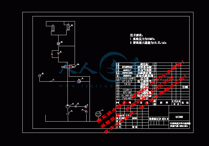
液压系统图(3号图纸);

设计说明书一份(正文部分不少于6000字)

毕业设计(论文)进度安排:

序号毕业设计(论文)各阶段内容时间安排备注

确定毕业设计题目,查阅并收集整理相关资料2014年12月

确定研究方法,分析处理数据,撰写论文大纲2015年1月

构思论文内容,设计开题报告,完成论文初稿的撰写2015年3月

论文修改润色,完成论文终稿,送交指导老师评审,进行答辩2015年4月

摘  要

本次毕业设计对象是液压升降平台,这套装置主要用于举升重物。它的举升高度为1米,举升重量为1吨,其动作主要是由两个双作用液压缸推动“X”型架,带动上板来实现的。该液压升降平台主要由两个部分组成:机械部分和液压部分,其中机械部分主要由上板架、下板架、内连杆和外连杆四部分组成。机械部分的设计、材料和结构,并进行测试和检查验收的分析,是否满足强度、刚度的要求,分析和验证结果表明,机械结构的设计可以满足要求。在对液压控制系统的设计过程中,先进行了总体方案设计。当选择不同的液压控制回路的时候,在对各个回路进行了对比后调速回路我选择了进油口节流调速回路;卸荷回路我选择了带有二位二通电磁换向阀的卸荷回路;保压回路我选择的是用液控单向阀的保压回路。确定了各种基本回路后,又确定了液压系统的传动形式,由于开式系统所具有的系统简单和散热条件好等优点,所以把传动系统确定为开式系统。在拟定液压系统原理图后,对液压元件及辅件进行了设计、选择,并对其进行校核。经过计算后液压缸选定为45毫米的液压缸,液压泵选定为齿轮泵,根据系统工作的最大功率我选择的电动机为Y112M-4行三相异步电动机。在确定泵后,又对其他的元件及辅件进行了合理的选择,最后确定各种元件后,进一步完成了我的设计题目。

关键词: 液压; 升降平台; 上板架; 下板架; 内连杆; 外连杆

Abstract

I graduated from the current design is done mainly hydraulic lifts, mainly divided into two parts: mechanical and hydraulic parts. Mechanical parts which I think the main needs to be considered is the subject of several major part of the intensity: on board planes, under the board planes, within and outside link connecting rod. In this part of my four were on board from top to bottom-line Analysis of the internal and external linkage, I had the strength check. After my analysis and after checking I think I can satisfy the design requirements. Then I entered the various parts of the hydraulic choice. In the choice of the hydraulic control circuit all the time, in the loop on a comparison of the governor after I selected the import speed loop circuit; unloading loop I chose the valve of the unloading circuit; packing circuit I have chosen The use of one-way valve controlling the packing circuit. In determining the needs of the various circuit I, I'm sure I wear the hydraulic system of fixed form, according to open-system and the system simple cooling system features good condition, I set my drive system for open - System. On the other hydraulic components accessories choice, I had to them after the calculation of the hydraulic cylinders after I voted 45 mm of hydraulic cylinders, according to the transmission gear pump stability, I take my pump as a gear Pump, according to my system the maximum power of the work I elected to the motor Y112M-4 to three-phase asynchronous motor. I set the pump, I also based on this I need the yuan other accessories for a reasonable Choose, finally, I identified a variety of components, further complete the design of the topics I.

Keywords:Mechanical;  Hydraulic;  Panels from top to bottom;  Inside and outside link

目  录

1  绪  论1

2  确定液压系统方案1

   2.1确定基本回路1

       2.1.1卸荷回路1

       2.1.2 调速回路的确定4

       2.1.3保压回路的确定5

   2.2液压传动系统的形式确定7

   2.3 液压系统原理图7

3  设计、选择液压元件、辅件8

   3.1确定液压缸系数8

       3.1.1 初选系统压力8

   3.2 液压辅助元件的计算及选择9

   3.3油箱的设计10

       3.3.1油箱的设计要点10

       3.3.2油箱容积计算10

   3.4  其它元、辅件的选择11

       3.4.1.吸油滤油器11

       3.4.2选择滤油器的基本要求11

       3.4.3溢流阀的选择11

       3.4.4压力表开关、单向节流阀选择11

       3.4.5 液控单向阀的选择11

   3.5阀块的设计12

4  效率的计算13

   4.1计算沿程压力损失13

   4.2效率计算15

   4.3 系统发热与温升计算15

   4.4 液压系统的一般使用和维护16

5  结论17

致谢18

参考文献19

1  绪  论

在运动过程中液压传动可以实现调速方便和无级调速。由于液压传动的出现,因而使机器结构得以简化,零件的数目也随之减少。由于油液充满了液压系统,对各液压元件有冷却和润滑的作用,使之不容易被磨损,又因为容易实现过载保护,所以寿命长。液压传动易于实现系列化,标准化,组件的制造和设计并易于推广。

液压升降平台是一种经济实用,安全可靠,升降平稳,操作简单,并广泛应用于医药,仓库,生产线及造纸行业的机械,主要用于有高度差的生产流水线来货物运送;物料上线、下线;通过调节工件高度进行工件装配;从高的地方给料机运送料;大型设备进行装配时部件的举升;大型机床下料和上料;仓储装卸的地方以及用叉车进行快速装卸货物和搬运车辆配套等。因此,设计与研究液压升降平台以及其液压系统具有重要意义。

我国气动、密封和液压工业虽取得了较大的进步,但相对于主机的发展需求,以及与世界先进水平之间的比较,还存在不小的不足和差距,主要在可靠性、性能和产品品种等方面反映。

2  确定液压系统方案

液压系统的设计的确是液压系统方案相当重要的一个环节。其目的是选择不同的回路,并把各种回路组成一个整体的系统,方便以后原理的确定。

在理论课上,我们知道由一些简单的基本回路可以通过结合构成复杂的液压系统,也可以说任何复杂的回路都是由一个个简单的回路组成。而组成基本回路的又是液压元件。所以组成液压系统,需要依据液压系统的性能特点和动作要求选择适宜的液压元件。

这次毕业设计升降平台的液压系统要求为:要求升降机由原始高度0.6米,举升高度为1米,其需举升的重量为1吨。完成的毕业设计必须能够达到以上要求,并可以完成举升的动作,同时需要考虑经济上以及系统效率的一些条件和问题。

参考文献

[1]  宋锦春,苏东海. 液压与气压传动.北京:科学出版,2006

[2]  李壮云,葛宜远. 液压元件与系统.北京:机械工业出版社,2004

[3]  雷天觉.新编液压工程手册.北京:北京理工大学出版社,1999

[4]  成大先.机械设计手册.北京:化学工业出版社,2004

[5]  岳继光.液压技术的发展趋势.工程设计,1998,1:55-57

[6]  吴根茂.液压控制的发展趋势.工程设计,1997,3:23-25

[7]  乔俊飞,孙雅明,柴天佑.液压系统中压力的自适应能力.电工技术学报,2000,3:11-14

[8]  杨尔庄.二十一液压技术的新突破.中国机电报,2000

[9]  杨尔庄.液压技术的发展动向及展望.第三届全国流体传动及控制学术大会会议文集,2004

[10]  王旭.国内液压产品的现状.对外经济贸易大学学报,2000,4:15-17

[11]  黄文豪.液压控制问题及展望.液压气动与密封,2002,6:5-7

[12]  李晨.我国液压传动的现状及发展.山西建筑,2003,12:9-12

[13]  张红.液压技术的展望.合肥联合大学学报,2000,4:15-17

[14]  鄂中凯.机械设计课程设计.沈阳:东北大学出版社,1992

[15]  机械设计手册联合编写组.机械设计手册.北京:化学工业出版社,1987

[16] Wasser,R.James.  Dry Seal Technology for Rotating Equipment Lubrication Engineering,1993,6(34):2587-2592

[17]letsion. Future, Mechanical.Seal.Development.LubricationEngineering,

1990,3(11):1235-1242

内容简介:
中国地质大学长城学院 毕业 设计 ( 论文 )任务书 学生姓名 胡云霄 学号 05211604 班 级 机制六班 指导教师 杨义勇 职称 教授 单 位 中国地质大学(北京) 毕业 设计 ( 论文 ) 题目 升降平台的液压系统设计 毕业 设计 ( 论文 ) 主要内容和要求: 本次毕业设计对象是液压升降平台的 液压系统 ,这套装置主要用于举升重物。 其动作主要是由两个双作用液压缸推动“ X”型架,带动上板来实现的。该液压升降平台主要由两个部分组成:机械部分和液压部分,其中机械部分主要由上板架、下板架、内连杆和外连杆四部分组成。 设计 参数: 举升高度为 1 米,举升重量为 1 吨 。 要求: 利用所学的理论知识,学会如何解决实际问题,设计出规范化、标准化的图纸。 毕业 设计(论文) 主要参考资料: 机械设计、液压传动、机械制图、材料力学、机械设计手册、互换性与测量技术基础 nts 毕业 设计(论文) 应完成的主要工作: 液压缸 装配图一张( 0 号图纸); 油箱图一张( 0 号图纸); 液压缸活塞杆图一 张( 1 号 图纸 ); 液压缸缸盖图一张 ( 2 号图纸); 液压缸缸底图一张( 3 号图纸); 液压系统图 ( 3 号图纸); 设计说明书一份(正文部分不少于 6000 字) 毕业 设计(论文) 进度安排: 序号 毕业 设计(论文) 各阶段内容 时间安排 备注 确定毕业设计题目,查阅并收集整理 相关资料 2014 年 12 月 确定研究方法,分析处理数据,撰写 论文大纲 2015 年 1 月 构思论文内容,设计开题报告,完成 论文初稿的撰写 2015 年 3 月 论文修改润色,完成论文终稿,送交 指导老师评审,进行答辩 2015 年 4 月 课题信息: 课题性质: 设计 论文 课题来源: 教学 科研 生产 其它 发出任务书日期: 指导教师签名: 年 月 日 nts 教研室意见: 教研室主任签名: 年 月 日 学生签名: nts 中国地质大学长城学院 本科毕业设计外文资料翻译 系 别: 工程技术系 专 业: 机械设计制造及其自动化 姓 名: 学 号: 2015年 2 月 15 日 nts CAD 技术在液压系统机械中的应用 产品发展的主要目标是在一个短的时间的设计过程中,获得低价格的产品和最终产品的最佳表现。根据这些目标,产品设计必须使用一些先进的 CAD - CAM, CAE 软件模块和互联网的在线三维部分目录(或多或少标准目录)。通 过使用不同的 CAD - CAM, CAE 软件的一些模块得到的好处是可以用低价格(这是没有必要所有的软件,只有一些特定的模块,这些软件(具体到工程领域)获得最好表现的模块。三维互联网上的在线目录提供的优势是很容易找到有关机械元件的有用信息(如价格,技术特点,三维模型等),对于相关产品的研发起到很大的推动作用,例如,液压系统,旋转楼梯等。 关键词: CAD/CAM 技术,转台,液压系统,齿轮传动。 现在,业内的高度竞争促使产生新的,更好,更便宜的产品。汽车制造商已经处理了客户日益增长的需求。他们必须不断提高产 品的构思方法,以现代化的组织结构,以创造一个流畅的链接,而没有研究,设计,制备,制造,商业化和工作产品的生命之间的限制。 要成为一个更加具有国际竞争力公司,他须有产品的多样性与不断变化,该公司必须现代化,提高生产系统的灵活性。 该公司发现,一种产品的交互设计是最有效的工具,用于分析评价结束。因此,互联网数据基础和的 CAD - CAM - CAE 软件的使用也带来视觉的几何数据基础和工业设计。工艺和产品开发使用计算机和网络环境可以获得大量成本和时间的节约。 在市场上有许多的 CAD - CAM, CAE 软件为工程 设计人员提供设计一个三维虚拟空间的很多具体的工具。 二,运用多种 CAD - CAM 的 CAE 技术软件包 这些类型的软件都代表一个非常有用的工具在产品开发设计过程中的作用。人们通过使用它可以创建一个三维虚拟产品,从模拟的角度分解成许多点,以改善其特性(非技术性的或技术性的)。 这些软件更好的应用于航空,汽车,机械等行业。今天单一的 CAD - CAM, CAE 软件在工程领域的表现有些不能涵盖整个工业的高场演出。这些软件的另一个主要缺点是一个完整版本的价格非常高。通常的价格是起价几千欧元。 对于大多数的 CAD - CAM, CAE 软件有三个优势: 1 - 软件的是结构化模块,即使在同一地区(例如:在 CATIA 机械设计中:部分设计 ;优势钣金设计,模具设计,管道设计和曲面设计等) ; 2 我们可以只买一些具体的一揽子关于电脑辅助设计,计算机辅助制造,计算机辅助工程的部分 ; 3 - 所有这些软件均容许以节省许多公共文件格式 例如( date:二维的 drawings,三维固体一步的 dxf , IGES 等)。这些类型的文件可以打开几乎所有在某些特定条件下的CAD - CAM, CAE 软件 对于一个复杂的产品(例如 :在汽车行业),其中需要许多复杂曲面造型。单一的 CAD - CAM, CAE 软件是不够的。在这种情况下,解决方法是使用不同的 CAD - CAM, CAE 软件中一些表现突出的具体模块。 3。在产品开发中利用网络设施。 如今互联网的发展提供了通过电子邮件传播最新的浪潮,文件传输,远程登录访问,交易应用,等等,等等。 互联网的最流行的部分原是万维网,原因是在那里任何人都可以访问同一个按钮单击超文本网页。互联网的普及,推出了众多的社会和伦理问题。最近,互联网已经被批评为未经nts审查的信息,但其教育价值一直被 人们所公认的称赞。 在工程领域的互联网被用来传播信息和公司的广告。今天,所有的大公司都在互联网上提供了许多他们产品的信息。在机械工程领域的大多数公司也提供有关产品(许多有技术特点的免费文件,免费二维图纸和三维模型免费目录),价格,演算技术软件(例如:轴承斯凯孚等)。 在互联网上存在着许多拥有专用产品开发水平的网站。从图 6(螺丝,轴承,滑轮小学部分标准目录开始,皮带,齿轮等)和完成复杂的产品(如工业机器人 - 图 7)互联网是一个在设计过程中所有的同类产品的有用工具。 互联网的缺点是不断增加的信 息的多样性和传播途径。最大的问题是如何找到这个虚拟空间有用信息。 3.1 在互联网上查找有用的三维目录 今天互联网上的信息的结构分为网页。几乎所有的公司都在世界上的网页,以提供更多有关其产品的信息。 有三种方式搜索: 1 - 寻找到一些具体的工程领域的公司。如果公司的名称,通常被称www.( company) .com!(例如: SKF 有 )。如果不是,一个简单的方法是使用搜索网站如谷歌( 搜索网站)和关键字的公司名称 ; 2 - 找一些具有相似产品的公司他 们会有相关公司的连接,还能使用关键字搜索网站谷歌和类似产品公司技术言语形容的产品。例如找到轴承公司可以使用:如“轴承”关键字,“球轴承”等 ; 3 - 寻找某些特定产品(标准或不)为特定的工程领域,建议使用专用的门户网站。门户网站是其中包含的 信 息 , 并 为 特 定 领 域 网 站 的 链 接 。 (例如/suppliers/bearings.html)。 对在工程领域的互联网公司在介绍他们的产品目录结构。有两种类型的网站目录。 一个是在著名的格式 PDF( 便携式文档格式)。为了找到这是推荐使用的搜索类型目录,经过特定的关键字,首字母缩写“ PDF 格式”。它的优点是使用的 PDF 目录,所有有关的产品所需的资料,为单文件,它可以打印提交。 另一种是交互式的在线目录有一些类似的优势: 1 - 查找所有的产品(包括 PDF 格式的信息), 2 - 在线演算软件, 3,产品可直接到 CAD - CAM 的实施 - CAE 软件。为了找到这种类型的目录,建议用“三维目录关键词在网上与关键字相结合的技术”。例如在网上找到一个齿轮目录三维它可用于搜索下一个字符串使用:“齿轮三维目录上线” 3.2 使用三维零件目录 在图 9 给出了一个三维齿轮目录搜索结果的屏幕捕获。用红色箭头标记为可能的三维互联网地址目录。在红色矩形标志着交互式目录地址图 10 介绍。在图 10 给出了它提供免费的3D 和 2D 技术产品目录门户。由于它是提出了一个例子目录威尔在齿轮设计中使用的数字 5所列。选择在这个目录有一个威尔 指定所有必要的参数: 1.直径 ; 2.齿数 ; 3.Material; 4.齿形 风格 ; 5 质量等级 6.压力角度 ; 7.孔尺寸 ; 8.齿宽 ; 9.齿间距 ; 10.轮毂直径。 ( N/A=无轮毂)。 在图 11 的技 术特点中提出了选择齿轮的所有特征在此目录(可通过 https: / /sdp - ) ;价格;进入相关的 CAD - CAM - CAE 系统可直接执行的文件格式。 它的三维模型被选中了 step 格式(用于固体组件的格式)。建成后的 CAD 软件实现几个小的修改,是基于坚实的威尔与齿轮按设计要求。它建了一个关键的键槽和一个圆形孔(基于方便建模的原因)。对于减速器,只有部分相关与箱体和主轴设计。在图 14 A 的标记目录(齿轮,螺丝,轴承,键与) b 图是在 CATIA V5 的设计的基本要素。 nts本文中标准建模和分级建模概念 被确定为 RMTs 建模方法的主要特点。 RMTs 的模块化结构使这种建模方法很有益处,因为这些模型包含了所有可重构的重要特征 17: 1模块化:(子)组件建模模块化 2可集成:该模块可以通过其连接端口与其他模块集成 3定制:详细程度包括了模型模块都可为单个组件进行定制 4可重构性:模型可以很容易地从一个配置转换到另一个 5诊断性:可方便地进行模块的模型验证 本文介绍的方法可以将建模任务分为两个步骤:( 1)开发组件模型;( 2)装配配置模型。虽然第一步仍然需要大量的建模知识,第二步更系统,甚至将来要实现自 动化。此外,两个步骤各有侧重:第一步的重点是组件内动态,而第二个步骤重点是组件之间的动态。 相对于伺服轴建模现有的方法,各个不同的 RMTs 配置都是一个潜在的新建模问题,本文提出的方法允许配置模式更快的发展。配置可以使用库中的模型模块快速组装,假若如此,使用在给定配置的所有组件在模库中都有对应的模块。因此,一个完善的模型库对这一方法的有效性是必不可少的。 对机床的机械部件三维多体建模方法推动了机械领域的模块化。因此,机床滑动模型可用于任何配置,例如在一个滑台移动有更多约束的环境下而不需要特别的滑台模型。以多体的方法,开发通用组件模型可以没有组件接口的先验知识。然而三维多体方法的一个缺点是通用模型可能比某一实际配置的需求更复杂。例如,在给定的配置中一个组件可能只是被限制在一个平面运动中,在这种情况下,三维模型就过复杂了。该模型应该简化,否则模型中不必要的复杂性降低了模型的计算效率。拟议的模块化建模方法将从集成模型降阶算法中受益。这将是今后工作的重点。 由于铣削加工切削用量及切削得力很大,同时又是多刃断续切削,加工时很容易产生振动,因此设计铣床夹具时应注意:夹紧力的大小必须调整合适,夹紧力设置过小,工件可能在加工过程 中移动而破坏夹具定位,不仅严重影响质量,还可能造成事故;夹紧力过大,不但会使工件和夹具本身产生变形,其加工质量也不高;夹具的安装要准确可靠,即安装及加工时要正确使用定向键、对刀装置;夹具要有足够的刚度和稳定性,设计结构要合理。车床夹具一般都是在悬臂状态下工作,为保证加工过程的稳定性;夹具结构应力求简单紧凑,轻便且安全,悬伸长度尽量小,使重心设计靠近主轴前支承。为保证安全 , 夹具体应制成圆形,加具体上的各元件不允许伸出夹具体直径之外;夹具的结构还应便于工件的安装、测量和切屑的顺利排出和清理。 目前,该机构被认 为是刚性,这并不总是很接近。为了能够研究结构动力学的影响,柔性的机构模式也应开发并添加到模库内。 最后,值得注意的是商业可用软件包如 ADAMS,、 DADS、 EASY5、 Dymola 等也可用于RMTs 建模的目的。 然而,采取统一强大的键合图提供的功能 基础方法,并简化未来的模式使其更易于实施,那么键合图就被选为建模语言。 结论 通过使用不同的 CAD - CAM - CAE 技术性能为基础的软件系统,不同的模块,优化工艺设计,可从技术角度来选择,无需额外费用。无需为了一个单一的 CAD - CAM, CAE 系统模块买一些没有更好模块的软件花费更高的费用。 通过使用在线互动目录的设计过程会更加简单。通过对相关的所有技术和非技术的数据元素使用,设计人员可以很容易做出产品成本推估(从各个要素的角度的)。 利用的 CAD - CAM, CAE 软件和互联网设施的产品开发的主要优势是耗费时间很短,可以致力于设计过程。这种方法提高约 70-80。 nts参考: 1康斯坦丁伊斯帕斯,米龙,克里斯蒂娜莫霍拉,多雷尔安尼亚,研究有关的机械系统的综合概念,第一届国际计算机及解决方案在制造工程会议科姆( 04),布拉索夫 , 2004 2吉奥内亚第一部分,安尼亚第四部分 - “计算机的管理使用计算机辅助设计的虚拟原型”,关于制造系统 ICMaS 国际会议论文集,作者 爱氪迪曼 罗曼, 2002 年的布加勒斯特 Application of CAD technology in the construction machinery nts The main goals to the product development are to obtain a short time of design process, a low price and best performances of the final product. According to these goals, the product design must use some modules of advanced CAD-CAM-CAE software and the internet on-line 3D catalogs for some parts (more or less standard). The advantage obtained by using some modules from different CAD-CAM-CAE software is to use the most performant parts of these software (specific to the engineering fields) at a low price (it isnt necessary all the software, only some specific modules). The internet 3D on-line catalogs offer the advantage to find very easy useful information about mechanical elements (prices, technical characteristics, 3D models, etc,). Key words: CAD-CAM swivel table sighter tower machine 1.INTRODUCTION Now, in the industry exists a high competition to produce new, better and cheaper products. The manufactures have to deal with the increasing demands of the customers. They have to improve continuously the conception methods of the products, to modernize the organization structure in order to create a fluent link, without limits, between studies, design, preparation, manufacturing, commercialization and working life of the products. To become more competitive into a world with diversity of products, with continuous changes, the companies must modernize and increase the flexibility of the production systems. The companies find out that the interactive design of a product is the most efficiently tool for analysis end evaluation. So the use of internet data base and CAD-CAM-CAE software creates visual data base and industrial geometry design. Process and product development using computers and internet environment allow a substantially costs and time economy. On the market there is a lot of CAD-CAM-CAE software which offer specific tools for engineering design into a tri dimensional virtual space. 2.USING MULTIPLE CAD-CAM-CAE SOFTWARE PACKAGES These kinds of software are representing a very useful tool in products development design process. By using them it can be created a 3D virtual product, simulate from many point of view 1, in order to improve its characteristics (technical or non technical). Some of these softwares have better performances for some engineering fields as aeronautics, automotives, mechanical etc. Today single CAD-CAM-CAE software cannot cover the entire industrial field for high performances. Another major disadvantage of that softwares is very high prices for a full version. Usual the prices are starting from several thousands of EUR. There are 3 advantages for the most CAD-CAM-CAE softwares: 1 - the softwares are structured in modules, even in the same area (for example: in CATIA in mechanical design are: part design; sheet metal design, mold design, wierframe and surfaces design etc); 2 - it can be bought only some specific package regarding computer aided design, computer aided manufacturing or computer aided engineering; 3 - all these software allow to save date in some commune file format (for example: dxf for 2D drawings, step for 3D solids; iges for nts3D surfaces etc). These types of files can be opened by almost all CAD-CAM-CAE software in some specific condition For a complex product (ex. in automotive industry) which need complex surfaces for modeling a single CAD-CAM-CAE software isnt sufficient. In this case the solution is to use some high performant specific modules from different CAD-CAM-CAE software. 3. USING INTERNET FACILITIES IN PRODUCT DEVELOPMENT. The growth of the Internet today offers the newest wave of communication through electronic mail, file transfer, telnet access, transaction applications, and much, much more. The most popular part of the Internet is the World Wide Web, where anyone can access hypertext pages with the click of a button. The popularity of the Internet has launched many social and ethical issues. Recently, the Internet has been criticized for its uncensored information, but has been praised for its educational value. In engineering field the internet is used for information dissemination and company advertising. Today all the big company offers many information about their products directly on the internet. In the mechanical engineering fields the most companies offer free catalogs about products (free documentation about technical characteristics, free 2D drawings and 3D models), prices, calculus technical software (ex: bearings SKF) etc. On the internet exists dedicated sites for all level of product development. Starting from standard catalogs for elementary parts fig.6 (screws, bearings, pulleys, belts, gears etc) and finished with complex products (like industrial robots fig.7) the internet is a useful tool in design process for all kind of products. The disadvantage of the internet is the increasing diversity of information and the way of dissemination. The big problem is how to find utile information in this virtual space on internet. 3.1 Finding useful 3D catalogs on internet Today on internet the information is structured into web pages. Almost all the companies in the world have web pages in order to offer more information about their products. There are 3 ways to search: 1 - to find a company into some specific engineering fields. If the name of company is known usually the site is www。( names) .com (ex: SKF has ). If is not, an easy way is to use a searching site as google ( ) and as keywords the company name; 2 - to find some companies witch have similar products it is recommended to use searching site as google and keywords technical words witch describe the product. For example to find bearing companies it can be use: keywords like “bearings”; “ball bearings” etc.; 3 - to find some specific products (standard or not) for a specific engineering field it is recommended to use dedicated portals. A portal is a site which contains information and links to specific sites for a domain. (ex. /suppliers/bearings.html). On internet in the engineering fields the companies presents their products structured in catalogs. There are two types of catalogs on web. One is in well-known format PDF (portable document format). To find catalog of this type it is recommended for searching to use, after specific keywords, the acronym “PDF”. The advantage ntsusing a pdf catalogs is that all the needed information about a product is presented into single file, which can be printed. Figure 3 shows the schematic representation of a generic rigid body with N connection ports, which is one of the main model modules in the library. The ports correspond to points of interest on the rigid body, where the physical interactions with the environment occur. Bonds (lines with half arrows) are used to indicate that a port is a power port, i.e. the body can exchange energy with its environment through those ports, whereas active bonds (lines with full arrows) indicate signal ports, i.e. only information is transferred through these ports. The model library also contains three-dimensional joint models that can be used to describe the relative motions between the component models. These joint models are also developed in a modular way with ports, where they can be connected to other model modules. The library offers two ways to express the constraints: (1) stiff springs and dampers can be used to implement more realistic constraints or to approximate ideal constraints;(2) Lagrange multipliers can be introduced to express the constraints ideally. For a discussion of joint models the reader is also referred to 16.Once the model library is populated with some basic modular rigid body and joint models, the modeling procedure can be carried out as follows: The RMT components are broken down into subcomponents and each subcomponent is associated with a model in the library. If none of the model modules in the library can describe the subcomponent adequately, a new model has to be developed for that subcomponent and added to the library. Then, the models are assembled by following the topology of the components and using the necessary joint models. Once a component model is obtained, it can be stored in the library for reuse. Finally, the component models are assembled by following the topology of a given configuration to obtain the model of that configuration. The process is illustrated in Figure 4 as a flowchart and demonstrated in the following section through examples. The other is interactive on-line catalogs which have some advantages like: 1- to find all information for a product (including in pdf format), 2- on-line calculus software, 3 -the product can be directly implemented into CAD-CAM-CAE software. To find such types of catalogs it is recommended to use keywords as “3D catalogs on-line” in combination with technical keyword. For example to find a gears catalog 3D on line it can be use for searching the next string: “gears 3D catalogs on-line” 3.2 Using 3D component catalogs In figure 9 is presented a screen capture for the results of 3D gears catalog search. With red arrow is marked possible internet address for 3D catalogs. In red rectangle is marked the address for interactive catalog presented in figure 10. In figure 10 is presented a portal for technical products which offers free 3D and 2D catalogs. As example it is presented a catalog wheal used in design of gear presented in figure 5. For selecting a wheal in this catalog it has to specify all the necessary parameter: 1.Diametral Pitch; 2.No. Of Teeth; 3.Material; 4.Hub Style; 5.Quality Class; 6.Pressure Angle Degree; 7.Bore Size; 8.Face Width; 9.Pitch Dia; In figure 11 is presented all the characteristics available in this catalog (https:/sdp- ) for selected wheal as technical characteristics; prices; available file formats for direct implementation into CAD-CA
温馨提示:
1: 本站所有资源如无特殊说明,都需要本地电脑安装OFFICE2007和PDF阅读器。图纸软件为CAD,CAXA,PROE,UG,SolidWorks等.压缩文件请下载最新的WinRAR软件解压。
2: 本站的文档不包含任何第三方提供的附件图纸等,如果需要附件,请联系上传者。文件的所有权益归上传用户所有。
3.本站RAR压缩包中若带图纸,网页内容里面会有图纸预览,若没有图纸预览就没有图纸。
4. 未经权益所有人同意不得将文件中的内容挪作商业或盈利用途。
5. 人人文库网仅提供信息存储空间,仅对用户上传内容的表现方式做保护处理,对用户上传分享的文档内容本身不做任何修改或编辑,并不能对任何下载内容负责。
6. 下载文件中如有侵权或不适当内容,请与我们联系,我们立即纠正。
7. 本站不保证下载资源的准确性、安全性和完整性, 同时也不承担用户因使用这些下载资源对自己和他人造成任何形式的伤害或损失。
提示  人人文库网所有资源均是用户自行上传分享,仅供网友学习交流,未经上传用户书面授权,请勿作他用。
关于本文
本文标题:升降平台的液压系统设计【优秀含6张CAD图纸+液压全套课程毕业设计】
链接地址:https://www.renrendoc.com/p-457974.html

官方联系方式

2:不支持迅雷下载,请使用浏览器下载   
3:不支持QQ浏览器下载,请用其他浏览器   
4:下载后的文档和图纸-无水印   
5:文档经过压缩,下载后原文更清晰   
关于我们 - 网站声明 - 网站地图 - 资源地图 - 友情链接 - 网站客服 - 联系我们

网站客服QQ:2881952447     

copyright@ 2020-2025  renrendoc.com 人人文库版权所有   联系电话:400-852-1180

备案号:蜀ICP备2022000484号-2       经营许可证: 川B2-20220663       公网安备川公网安备: 51019002004831号

本站为文档C2C交易模式,即用户上传的文档直接被用户下载,本站只是中间服务平台,本站所有文档下载所得的收益归上传人(含作者)所有。人人文库网仅提供信息存储空间,仅对用户上传内容的表现方式做保护处理,对上载内容本身不做任何修改或编辑。若文档所含内容侵犯了您的版权或隐私,请立即通知人人文库网,我们立即给予删除!