鉴定意见.doc

超声波电机的设计【7张CAD图纸+毕业论文】【答辩优秀】

收藏

压缩包内文档预览:
预览图 预览图 预览图
编号:471730    类型:共享资源    大小:4.44MB    格式:RAR    上传时间:2015-08-13 上传人:好资料QQ****51605 IP属地:江苏
45
积分
关 键 词:
超声波 电机 机电 设计 全套 cad 图纸 毕业论文 答辩 优秀 优良
资源描述:

目录

第1章 绪论3

1.1 超声波电机的定义与发展历史3

1.2 超声波电机的基本工作原理5

1.3 超声波电机的分类6

1.4 超声波电机的特点和应用6

1.5 超声波电机技术的展望7

第2章超声波电机的运动机理8

2.1 椭圆运动的分析8

2.2 驻波的产生及行波的合成10

第3章 超声波电机的理论计算与设计13

3.1 定子谐振频率的计算13

3.2 压电陶瓷换能器的设计和制作16

3.2.1 压电陶瓷的设计16

3.2.2 压电陶瓷材料的选用17

3.2.3 压电陶瓷的接线方式17

3.3 定子的设计及制作19

3.3.1 定子尺寸与行波超声波电机输出特性的关系19

3.3.2 定子的内外径尺寸的选择21

3.3.3 定子的振动模态的选择21

3.3.4 定子的齿形齿数设计21

3.3.5 定子的结构设计22

3.3.7定子材料的选择23

3.4 转子的设计及制作24

3.4.1 超声波电机转子的柔性要求24

3.4.2 定转子径向弯曲配合25

3.4. 摩擦层的设计26

3.5 定转子设计的总结26

第4章 超声波电机的驱动控制技术27

第5章 超声波电机整体结构设计30

第6章 全文总结32

参考文献33

致谢34

附录 英文翻译译文35


超声波电机的设计

摘要:超声波电机是一种利用压电陶瓷的逆压电效应工作的新概念、新原理电机。与传统电磁型电机截然不同,其驱动力矩并非由电磁感应产生,它利用压电陶瓷的压电效应使定子产生超声波振动,通过定子和转子间的摩擦力来驱动转子。由于超声波电机特殊的工作原理,它具有很多传统电磁电机无法比拟的优越性能,如结构紧凑、低速大转矩、响应速度快、不受磁场影响、断电自锁、可直接驱动负载等。正是由于超声波电机具有许多的优点和广阔的应用前景,成为当前世界范围内的一门新兴前沿课题。

本文主要以超声波电机为研究对象,设计超声波电机的实验样机。研究的主要内容可概括如下:系统地总结国内外超声波电机的发展历史和重要意义,介绍了超声波电机的工作原理、分类、特点及其应用前景。在对超声波电机相关理论研究的基础上,从超声波电机定子设计着手,详细介绍了超声波电机的设计过程。

关键词:超声波电机  压电陶瓷    


Design of Traveling Wave Ultrasonic Motor

Abstract:Ultrasonic motor is a use of the inverse piezoelectric effect of piezoelectric ceramic work of new concepts, new principles of motors. Very different from the traditional electromagnetic motor, the driving torque is not generated by the electromagnetic induction, which uses the piezoelectric effect to generate ultrasonic vibration of stator, through the friction between the stator and rotor to drive the rotor. Since the working principle of ultrasonic motors special, it has a lot of traditional electromagnetic motors can not match the superior performance, such as compact structure, low speed high torque, fast response, free from magnetic influence, power locking, can directly drive the load and so on. It is because of ultrasonic motor has many advantages and potential applications, become the world's a new frontier subject.

     In this paper, a rotary traveling wave type ultrasonic motor for the study, designed the experimental prototype ultrasonic motor. The main content can be summarized as follows: The system sums up the history of the development of ultrasonic motor home and abroad and the importance of introducing the principle of ultrasonic motors, classification, characteristics and application prospects. In the theory of ultrasonic motors based on ultrasonic stator design from the start, ultrasonic motor described in detail the design and production process.

Key words:  Ultrasonic Motor   Piezoelectric ceramics  


第1章 绪论

本章主要介绍超声波电机定义与发展历史、基本工作原理、分类、特点及其应用及对超声波电机技术的应用展望。

1.1 超声波电机的定义与发展历史

超声波电机(Ultrasonic Motor,简称USM)是一种新型的直接驱动型微电机,其原理完全不同于传统的电机,没有绕组与磁路,不以电磁作用传递能量,因而有很多不同于传统电机的特性。超声波电机一种利用超声波振动能作为驱动源的新原理电机,是电机制造、机械振动学、摩擦学、功能材料、电子技术和自动控制等学科综合交叉发展的产物,是利用压电材料的逆压电效应,把电信号加到压电陶瓷-金属构成的定子上,使定子表面的质点产生一定轨迹的机械振动,驱动转子运动的新型电机。由于定子的振动频率多数处在超声频范围,所以被称为超声波电动机。超声波电机具有能量密度大、响应快、结构紧凑、低转速、大力矩、不受电磁干扰、断电自锁等优点。 在微型机械、机器人、精密仪器、家用电器、航空航天、汽车等方面有着广泛的应用前景。

USM是20世纪80年代随着科学技术的发展才备受重视并得到应用的一种新型直接驱动电机,其发展史却可追溯到20世纪40年代。20世纪40年代,人们就知道了超声波电机的这个驱动原理,然而由于当时压电陶瓷材料以及超声波电机理论技术的滞后,超声波电机只能是“空中楼阁”,没有得以实现。一直到80年代初,具有高转换效率的压电材料出现以后,再加上电力电子控制技术的发展,才逐步研制出各种各样的超声波电机。

超声波电机的发展历史过程总结如下:

利用弹性振动获得动力的尝试是从钟表开始的。1961年,英国的Bulova Watch Ltd钟表   公司首次提出了用弹性体振动能量作为驱动力                                  的理论,并研制成音叉驱动的手表,在国际上引起了轰动。

1973年, IBM公司的H.V.Barth博士首先研制成功原理性超声波电机,如图1.1所示。该电机由一个转子和两个驱动振子构成,两个振子由PZT提供振动,其前部压置在转子上,保持摩擦接触。当振子(1)激振时转子顺时针方向回转,当振子(2)激振时,转子逆时针方向回转。与此同时,原苏联的V.V.Lavrinenco等人也研制出几乎与Barth具有相同原理的几种超声波电机,并给出了超声波电机结构简单、成本低、低速大转矩、单位质量功率大、运动精确、能量转换效率高等一些基本特性。1978年,前苏联的Vasiliev等成功地构造了一种能够驱动较大负载的超声波电机,
内容简介:
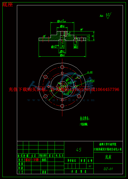
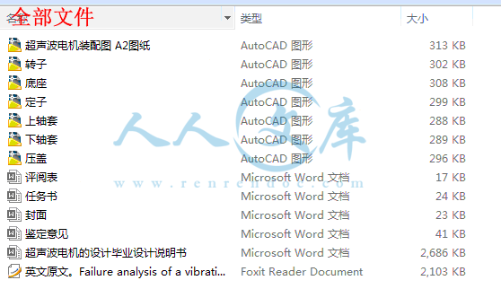
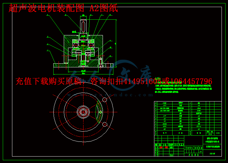
湘潭大学兴湘学院 毕业论文(设计)任务书 论文(设计)题目: 超声波电机的设计 学号: 2010963101 姓名: 罗悠 专业: 机械设计制造及其自动化 指导教师: 周里群 系主任: 刘伯希 一、主要内容及基本要求 超声波电机是国内外日益受到重视的一种新型驱动 电机,通过查找相关文献,熟悉其工作原理和运行机理,结合本科所学机械各学科方面的知识,完成超声波电机结构部分的设计。 主要研究内容包括以下几个方面 : 1 超声波电机的运行机理。 2 定子谐振频率的计算。 3 压电陶瓷换能器的设计和制作。 4 定子的设计及制作。 5 转子的设计及制作。 6 编写设计说明书:设计说明书按设计程序编写。 基本要求:学习查阅文献,具备综合归纳资料的能力;综合运用本科阶段所学知 识,分析与解决超声波电机结构设计过程中所遇问题;并利用 AutoCAD 软件绘制了其装配图和各个零件图;通过翻译 3000 字的外文资料获取国外在该行业的最新发展动态。 二、重点研究的问题 理解超声波电机的工作原理和运行机理,弄清其结构特点,定子谐振频率的计算,定子的设计及制作,转子的设计及制作;理解超声波压电陶瓷和压电振子的特性,弄清超声波电机的 振动特性及动力响应特性;理解超声波电机的驱动和控制及超声波电机的分析与设计。设计一台超声波电机。 nts三、进度安排 序号 各阶段完成的内容 完成时间 1 选题 第 1 周 2 查阅与收集资料 第 25 周 3 超声波电机结构的设计 第 69 周 4 完成所要求图纸 第 1011 周 5 完成设计说明书 第 1213 周 6 进行最后的修改 第 14 周 7 答辩 第 15 周 四、应收集的资料及主要参考文献 1 刘晋春 , 特种加工,第五版 M.机械工业出版社 .2008 2 史敬灼,超声波电机运动控制理论与技术 .北京 :科学出版社 .2011.10 3 胡敏强,金龙,顾菊平,超声波电机原理与设计 . 北京 : 科学出版社 .2005 4 姜楠,方光荣,刘俊标,束娜 . 国内外超声波电动机驱动技术的最新进展 . 微特电机 . 2005.9 5 赵淳生,对发展我国超声电机技术的若干建议 .微电机 .2006 6 胡敏强,超声电动机的研究及其应用 J.微特电机 .2000 7 淮良贵,纪名刚,机械设计 ,第六版 M.北京 :高等教育出版社 ,1996 8 郑凯,杨义勇,胡仁喜 .Solid Edge 应用教程 M.清华大学出版社, 2008.4 9 芦亚萍,孟繁琴,袁云龙 .超声波电机研究现状 .微电机 .2005 10 杨明,阙沛文 . 超声电机变频驱动源的设计与分析 . 压电 与声光。 11 顾绳谷 ,电机及拖动基础,第四版 M. 机械工业出版社 .2007.10 12罗宗泽,罗圣国 .机械设计课程设计手册 M.高等教育出版社, 2006.5 nts 湘潭大学兴湘学院 毕业设计说明书 题 目: 超声波电机的设计 专 业: 机械设计制造及其自动 学 号: 2010963101 姓 名: 罗悠 指导教师: 周里群 完成日期: 20140520 ntsKeywords:Failure analysisFretting wear simulatorVibrating shaftHigh temperature and high pressure waterFracture surfacemine the failure initiation and failure mode. It was found that the failure had initiated at aof thesenuclear fuel rods, which have the following dimensions; 9.5 mm outer diameter, 0.6 mm wall thickness and about a 4 mlength. Because of the FIV phenomenon by a primary coolant, these slender fuel rods could easily vibrate, thus they aresupported by several spacer grid structures as shown in Fig. 1. Each cell of a spacer grid structure consists of two springsand four dimples. Therefore, a nuclear fuel rod is supported by a certain amount of spring force, which depends on the springshape and its stiffness. Under a high temperature in an operating NPP condition, however, the contact force between the fuel1350-6307/$ - see front matter C211 2008 Elsevier Ltd. All rights reserved.* Corresponding author. Tel.: +82 42 68 8761; fax: +82 42 863 0565.E-mail address: leeyhkaeri.re.kr (Y.-H. Lee).Engineering Failure Analysis 16 (2009) 12381244Contents lists available at ScienceDirectEngineering Failure Analysisdoi:10.1016/j.engfailanal.2008.08.013temperature (C24320 C176C), pressurized water (C2415 MPa) and radioactive environment. This condition inevitably results inmaterial degradations such as a corrosion, fatigue, irradiation embrittlement, creep, etc. during their operation. Anothersevere condition for degrading structural materials is known as a flow-induced vibration (FIV) of relatively slender structuresdue to the rapid flow velocity of primary and secondary coolants, which results in fretting damages between these slenderstructures and their supporting structures. These kinds of fretting damages have been experienced in the major componentsof NPPs such as the nuclear fuel rods, steam generator (SG) tubes and control rods 1. Among these components, in ourlaboratory, the fretting wear phenomenon of nuclear fuel rods has been investigated in order to examine and develop a fret-ting wear mechanism and a defect-free fuel assembly (FA), respectively. Generally, a FA consists of 16C216 or 17C2171. IntroductionThe failure phenomena of mechanicalfrequently in various industries. Onecontact region between the vibrating shaft and the fuel rod holder jig and a fatigue crackwas propagated although it was difficult to prove it conclusively due to the heavily oxi-dized fracture surface. Near the failure locations, however, the thread hole was subjectedto a repeated loading due to the fact that the specimen holder jig had a circular motionfor simulating a vibration motion. This suggests that the vibrating shaft failure resultedfrom corrosion fatigue phenomenon because the fretting test had been performed at hightemperature (C24320 C176C) and pressurized distilled water (C2415 MPa) conditions. In this paper,the reasons for this failure and the fracture mechanisms are revealed and discussed byusing the OM and SEM results of the failure surface and the stress analysis of the contactregions between the vibrating shaft and the specimen holder jig. Finally, the above resultswere applied to a design change of the vibrating shaft.C211 2008 Elsevier Ltd. All rights reserved.structures by material degradations in extreme environments have been reportedexamples, is in nuclear power plants (NPPs). Generally, NPPs operate in a highFailure analysis of a vibrating shaft in a fretting wear simulatorYoung-Ho Lee*, Jae-Yong Kim, Hyung-Kyu KimKorea Atomic Energy Research Institute, 150 Dukjin-dong, Yuseong-gu, Daejeon 305-353, Republic of Koreaarticle infoArticle history:Received 11 July 2008Accepted 1 August 2008Available online 15 August 2008abstractRecently, a fretting wear simulator was developed in order to evaluate the fretting wearbehavior of nuclear components in high temperature and high pressure (HTHP) water con-ditions. After 500 h tests, however, two vibrating shafts among four were fractured, whichwere connected to a specimen holder jig by using a bolt. The fracture surface was examinedusing both an optical microscope (OM) and a scanning electron microscope (SEM) to deter-journal homepage: /locate/engfailanalntsY.-H. Lee et al./Engineering Failure Analysis 16 (2009) 12381244 1239rod and spring/dimple is gradually decreased due to a spring relaxation. In addition, the spring stiffness is also graduallyincreased because of an irradiation embrittlement of a spacer grid spring/dimple. Even though a certain amount of springforce is exerted on the fuel rod at its initial operation, a relatively small slip amplitude on the contact surface is unavoidableunder a severe FIV condition. Consequently, the contact force is gradually decreased and finally, a gap is opened up. ThisFig. 1. The schematic view of a nuclear fuel assembly that consists of 16C216 or 17C217 fuel rods and several spacer grid assembly.means that the fretting wear mode could be changed from a sliding wear to an impacting wear with increasing operatingtime. Another important point is that the vibration characteristics of a nuclear fuel rod also changed due to a contactcondition change of a fuel rod. Therefore, it is quite difficult to examine the fretting wear mechanism of a nuclear fuelrod in NPP operating conditions.A vertical type of a fretting wear tester (FRETONUS, FRTtting Tester Of NUclear Systems) for a HTHP water condition wasdeveloped in order to evaluate the fretting wear behavior of nuclear components 2. After 500 h tests, however, two vibrat-ing shafts among four were fractured, which were connected to a specimen holder jig by using a bolt as shown in Fig. 2.ItisFig. 2. Schematic views of the assembling method between the vibrating shaft and rod specimen holder jig and the fractured vibrating shaft after 500 htests at high temperature and pressurized water condition.ntsessential to evaluate the reason for their failure and to improve the vibrating shaft design to confirm the reliability of thefretting wear tester for a long experiment. In this study, the reasons for the failure and the fracture mechanisms are revealedand discussed by using the OM and SEM results of the fracture surface, measurement of the micro-vickers hardness and thestress analysis of the vibrating shaft. Finally, the above results were applied to a design change of the vibrating shaft.2. Fracture surface analysis2.1. OM observationThe vibrating shaft is made of a conventional high-carbon martensitic stainless steel (SUS 440C) and this material iswidely used as tools or blades for use in relatively corrosive atmospheres 3. The chemical composition and mechanicalproperties are listed in Table. 1. Fig. 3 shows the OM result of the fracture surface for the vibrating shaft. Due to the HTHPwater condition, the fracture surface was heavily oxidized and it was difficult to obtain metallographic proof by using theOM observation. However, it is expected that the failure was initiated at a contact region between the vibrating shaft andthe fuel rod holder jig because these two parts was assembled by using a bolt as shown in Fig. 2. During the fretting weartests, four vibrating shafts were reciprocated in their axial direction with a range of 200 lm, a frequency of 30 C176Hz and asinusoidal motion by two electro-magnetic actuators that were arrayed at an angle of 90o. To generate a circular motionof the fuel rod specimen which is regarded as a conservative simulation of an actual fuel rod vibration in operating NPPs,the phase difference of the sinusoidal waveform for the shake signals of two actuators is set to 90oas shown in Fig. 4. Whenthe fuel rod specimen is vibrated with a circular motion, the contact region of the vibrating shafts with the fuel rod holder jigis expected to experience fatigue loads. Generally, striation traces that are distinct proof for a fatigue failure could be foundeasily on a fracture surface, if the structural materials are fractured under the fatigue loading conditions. However, the oxi-dized fracture surface of the vibrating shaft was examined by using SEM without any cleanings because the striation tracescould be expected to remove by the oxide removal process (i.e. acid cleaning).2.2. Hardness variationBefore the SEM observation, it is necessary to examine the mechanical property changes of the vibrating shaft, because itwas exposed to the HTHP water condition during 500 h tests. So, a micro-vickers hardness of the fractured vibrating shaft1240 Y.-H. Lee et al./Engineering Failure Analysis 16 (2009) 12381244was measured and its result is shown in Fig. 5. It is apparent that the micro-vickers hardness value increased accordingto the exposed temperature for the vibrating shaft. This result corresponds well with the tempering temperature effectTable 1Chemical compositions and mechanical properties (room temperature) of a conventional high-carbon martensitic stainless steel (SUS 440C) 4CMnSiP S CrMoFeChemical compositions (wt%)1.0 1.0 1.0 0.04 0.03 17 0.75 Bal.Yield strength Tensile strength Elongation Elastic modulus Density Poissons ratioMechanical properties1280 MPa 1750 MPa 4% 200 GPa 7.8 g/cm30.3Fig. 3. OM result of the fracture surface for the vibrating shaft: arrows indicate the expected crack initiation region.ntsY.-H. Lee et al./Engineering Failure Analysis 16 (2009) 12381244 1241Fig. 4. Actuating mechanism of the fuel rod by using two electro-magnetic actuators in FRETONUS: note that the fuel rod motions are changeable byadjusting vibration amplitudes and phase difference between two actuators.on the mechanical properties of SUS 440C 4. In this study, the higher carbon martensitic stainless steel is likely to retain alarge amount of untransformed austenite. It is thought that a delayed transformation may occur as temperature fluctuationsin several fretting wear tests because the 500 h tests at about 320 C176C did not have a negligible effect on the stress relieving ofthe vibrating shaft material. In addition, it is possible that some loss in ductility may result from a hydrogen embrittlementthat is an important concern in martensitic stainless steels in a heat-treating atmosphere containing hydrogen in the form ofdistilled water.2.3. SEM resultsFig. 6 shows the morphology of the fracture surface by using SEM. It is apparent that the fracture surface was almost cov-ered with oxides and it is difficult to detect evidence of a fatigue failure such as striation traces. From a careful inspection ofthe results, however, weak striation traces appeared near a lateral outer surface. Also, a crack propagation trace was found atthe contact region between the vibrating shaft and the fuel rod holder jig even though its characteristic could not be defineddue to the severe oxidation in the HTHP water condition. One of the interesting results is that an impacting wear scarappeared in the fracture surface of the vibrating shaft. This result means that the impacting wear between the two fracturedsurfaces is generated after a fracture because the fractured vibrating shaft is continuously reciprocated by an electro-mag-netic actuator regardless of the shaft failure. So, it is expected that the fatigue striation traces had disappeared and were cov-ered by the impacting wear motion and by the wear debris with a severe oxidation, respectively. Consequently, the vibratingshaft failure is expected to be initiated by a contact fatigue at the contact region and then the contact force exerted by a boltFig. 5. Measurement result of the micro-vickers hardness according to the exposed temperature for the vibrating shaft.nts1242 Y.-H. Lee et al./Engineering Failure Analysis 16 (2009) 12381244screw will be decreased gradually. At this time, the initial crack propagation is gradually retarded and the contact conditionbetween the vibrating shaft and the fuel rod holder jig will be changed as shown in Fig. 7. So, it is necessary to examine thenew crack initiation region by using a stress analysis, which could verify the maximum stress region of the vibrating shaftduring a circular motion.3. Stress analysisIn order to analyze the stress distribution that the vibrating shaft experienced during the initiation of the new crack, theFE model with 10 mm in diameter and 233.5 mm in length was created by using the commercial 3D modeler, SolidEdge V.19as shown in Fig. 8. The displacement of the constrained cylinder at the left side is 0.2 mm and the connected region with theelectro-magnetic actuator at the right side is fixed. The 4 node linear tetrahedron elements were used for the vibrating shaft.Fig. 6. SEM micrograph of the fractured vibrating shaft surface.ntsFig. 7. Variation of contact condition between the vibrating shaft and the fuel rod holder jig after the retardation of initial crack propagation.Fig. 8. FE model of the vibrating shaft generated by using a commercial 3D modeler.Y.-H. Lee et al./Engineering Failure Analysis 16 (2009) 12381244 1243The FE model consisted of about 10,100 nodes and 47,200 elements. The used elastic modulus, yield strength, density andPoissons ratio of the commercial SUS 440C are listed in Table. 1. The commercial code, ABAQUS Standard ver. 6.63 5, wasused to post-process the model in order to calculate the Von-Mises stress of the vibrating shaft. The Von-Mises stress dis-Fig. 9. Model of Von-Mises stress distribution in the vibrating shaft.ntstribution in the vibrating shaft showed that the high stress concentrations were present at the edge of the thread hole andthe lateral outer surfaces as shown in Fig. 9. In particular, the lateral face experienced stresses in the magnitude of approx-imately 640 MPa. This value is about half of the yield stress of the vibrating shaft. It is considered that these high stress con-centrations are affected by the conservative boundary condition of the FE analysis. Consequently, the positions of the stressconcentration are in good accord with the crack generation traces revealed in the SEM observation. Based on this result, thedesign of the vibrating shaft was modified to reduce the stress concentration between the contact surfaces and the threadhole size of it was decreased to increase the fatigue life cycle.4. SummaryThe reason for the failure of the vibrating shaft in the fretting wear simulator was investigated by using a measurement ofthe micro-vickers hardness, OM & SEM observations and a finite element analysis. Due to the heavily oxidized fracture sur-face and the impacting wear between the two fracture surfaces after a failure, it is difficult to obtain the metallographic
温馨提示:
1: 本站所有资源如无特殊说明,都需要本地电脑安装OFFICE2007和PDF阅读器。图纸软件为CAD,CAXA,PROE,UG,SolidWorks等.压缩文件请下载最新的WinRAR软件解压。
2: 本站的文档不包含任何第三方提供的附件图纸等,如果需要附件,请联系上传者。文件的所有权益归上传用户所有。
3.本站RAR压缩包中若带图纸,网页内容里面会有图纸预览,若没有图纸预览就没有图纸。
4. 未经权益所有人同意不得将文件中的内容挪作商业或盈利用途。
5. 人人文库网仅提供信息存储空间,仅对用户上传内容的表现方式做保护处理,对用户上传分享的文档内容本身不做任何修改或编辑,并不能对任何下载内容负责。
6. 下载文件中如有侵权或不适当内容,请与我们联系,我们立即纠正。
7. 本站不保证下载资源的准确性、安全性和完整性, 同时也不承担用户因使用这些下载资源对自己和他人造成任何形式的伤害或损失。
提示  人人文库网所有资源均是用户自行上传分享,仅供网友学习交流,未经上传用户书面授权,请勿作他用。
关于本文
本文标题:超声波电机的设计【7张CAD图纸+毕业论文】【答辩优秀】
链接地址:https://www.renrendoc.com/p-471730.html

官方联系方式

2:不支持迅雷下载,请使用浏览器下载   
3:不支持QQ浏览器下载,请用其他浏览器   
4:下载后的文档和图纸-无水印   
5:文档经过压缩,下载后原文更清晰   
关于我们 - 网站声明 - 网站地图 - 资源地图 - 友情链接 - 网站客服 - 联系我们

网站客服QQ:2881952447     

copyright@ 2020-2025  renrendoc.com 人人文库版权所有   联系电话:400-852-1180

备案号:蜀ICP备2022000484号-2       经营许可证: 川B2-20220663       公网安备川公网安备: 51019002004831号

本站为文档C2C交易模式,即用户上传的文档直接被用户下载,本站只是中间服务平台,本站所有文档下载所得的收益归上传人(含作者)所有。人人文库网仅提供信息存储空间,仅对用户上传内容的表现方式做保护处理,对上载内容本身不做任何修改或编辑。若文档所含内容侵犯了您的版权或隐私,请立即通知人人文库网,我们立即给予删除!