说明书-铁丝缠绕包装机的设计——机架及总装的设计.doc

铁丝缠绕包装机的设计——机架及总装的设计【三维PROE】【毕业论文】【答辩优秀】

收藏

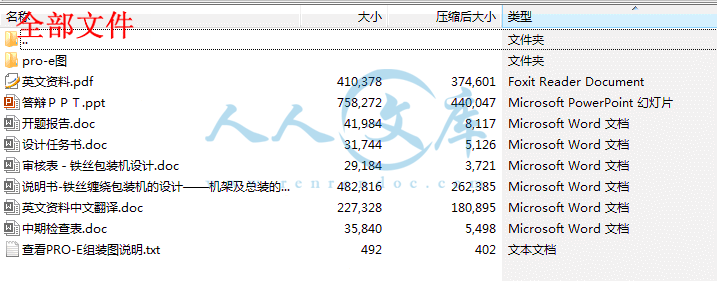
资源目录
跳过导航链接。
铁丝缠绕包装机的设计——机架及总装的设计【三维PROE】【毕业论文】【答辩优秀】.rar
说明书-铁丝缠绕包装机的设计——机架及总装的设计.doc---(点击预览)
设计任务书.doc---(点击预览)
英文资料中文翻译.doc---(点击预览)
英文资料.pdf---(点击预览)
答辩PPT.ppt---(点击预览)
查看PRO-E组装图说明.txt---(点击预览)
开题报告.doc---(点击预览)
审核表-铁丝包装机设计.doc---(点击预览)
中期检查表.doc---(点击预览)
pro-e图
00000.asm.1
00000.asm.2
00000.asm.3
00000.asm.4
00000.asm.5
00000.asm.6
00000cejia.prt.1
00000cejia.prt.2
00000cejia.prt.3
11111.asm.15
11111.asm.17
11111.asm.18
11111.asm.19
11111.asm.20
11111.asm.21
11111.asm.22
11111.asm.23
11111.asm.25
11111.asm.26
11111.asm.27
11111.asm.28
12ld02.prt.1
12ld03.prt.1
12ld04.prt.1
12ld05.prt.1
12ld05.prt.2
12ld06.prt.1
12ld06.prt.2
12lm02.prt.1
16ld.prt.1
16ld01.prt.1
16ld03.prt.1
16ld04.prt.1
16lm.prt.1
16lm01.prt.1
asm0001.asm.1
asm0002.asm.1
asm0003.asm.1
asm0004.asm.1
cejia.prt.1
cejia01.prt.1
cejia02.prt.1
cejia03.prt.1
cejia04.prt.1
cejia05.prt.1
cejia05.prt.2
cejia06.prt.1
cejia06.prt.2
cejiahuagan.prt.1
cejiahuagan01.prt.1
cejiahuagan02.prt.1
cejiahuagan02.prt.2
cejiahuagan02.prt.3
cejiahuagan03.prt.1
cejiahuagan03.prt.2
cejiahuagan03.prt.3
cejiashang.asm.1
cejiashang001.asm.1
ceshangjia.asm.1
changzhoucheng.prt.1
dai.prt.1
dai.prt.2
dai.prt.3
dai.prt.4
dai.prt.5
dailun.prt.1
dailun.prt.2
dailun.prt.3
dailundangquan.prt.1
dianji.asm.1
dianji.prt.1
dianji2.prt.1
dianji2.prt.2
dizuo01.prt.1
dizuo01.prt.2
dizuo01.prt.3
dizuo01.prt.4
dizuo01.prt.5
dizuo01.prt.6
dizuo01.prt.7
dizuo01.prt.8
dizuo01.prt.9
duanzhou.prt.1
duanzhou.prt.2
guangzhou.prt.1
guding.asm.1
gun.prt.1
jiajin3.prt.1
jiajin3.prt.2
jiajin3.prt.3
lian.prt.1
lian1.prt.1
liandai1.prt.1
liandai1.prt.2
liandai2.prt.1
lianlun.prt.1
lianzhouqi.prt.1
lm.prt.1
lm.prt.2
lm01.prt.1
lm01.prt.2
lm01.prt.3
lm02.prt.1
luoding.sec.1
mocalun2.prt.1
mocalun6.prt.1
pan3.prt.1
pan3.prt.2
pan3.prt.3
prt0001.prt.1
prt0002.prt.1
prt0004.prt.2
prt0006.prt.1
shangguding01.prt.1
shangguding01.prt.2
shangguding01.prt.3
shangguding02.prt.1
shangjia.prt.1
shangjia01.prt.1
shangjia02.prt.1
shangjia03.prt.1
shangjia04.prt.1
shangjia05.prt.1
shangshengjia01.prt.1
shangshengjia02.prt.1
shangshengjia02.prt.2
shangshengjia02.prt.3
shangsigang.prt.1
shoul.prt.2
sigan.prt.1
sigang.asm.1
sigang.asm.2
sigang.asm.3
sigang.asm.4
sigangyong.prt.1
sigangyong.prt.2
sigangyong.prt.3
tiesipan.prt.1
tiesipan.prt.2
tiesipan.prt.3
zhejia.prt.1
zhou6.prt.1
zhou7.prt.1
zhouchengduangai.prt.1
zhui.prt.1
zhui1.prt.1
zhui1.prt.2
zhui1.prt.3
zhui2.prt.1
zhui2.prt.2
zhujia01.prt.1
zhujia02.prt.1
zhujia03.prt.1
zhujia03.prt.2
zhujia04.prt.1
zhujia04.prt.2
zhujia04.prt.3
zhujia04.prt.4
zhujia04.prt.5
zhujia04.prt.6
zhujia04.prt.7
zhujia04.prt.8
zhujia04.prt.9
zhujiaoshanghuaban.prt.1
zhujiaoshanghuaban01.prt.1
zhujiaoshanghuaban02.prt.1
zhujiaoshanghuaban03.prt.1
复件 dianji.asm.1
压缩包内文档预览:(预览前20页/共26页)
预览图 预览图 预览图 预览图 预览图 预览图 预览图 预览图 预览图 预览图 预览图 预览图 预览图 预览图 预览图 预览图 预览图 预览图 预览图 预览图
编号:473027    类型:共享资源    大小:24.67MB    格式:RAR    上传时间:2015-08-17 上传人:好资料QQ****51605 IP属地:江苏
50
积分
关 键 词:
铁丝 缠绕 装机 设计 机架 总装 三维 proe 毕业论文 答辩 优秀 优良
资源描述:

摘  要

  本设计内容主要包括机架的设计,大转盘动力及结构设计,带动铁丝盘转动的摩擦轮动力源和机构的设计.除此之外另外还包括对电机的选择,轴,轴承,齿轮,带,链和螺钉等的设计选择和绘图。并运用pro-e,完成对各个零件的绘制,并完成组装图,最后完成对铁丝缠绕包装机的设计,并运用PRO-E绘图中的动力源使其运动 ,完成模拟缠绕包装过程。设计出成本较低,可靠性强,使用寿命长,节省劳动力,节省时间的自动铁丝缠绕包装机。本文设计了铁丝包装机的机架部分,包括对整个铁丝包装机机架上的所有零件的设计,校核和绘图。


关键词:铁丝缠绕包装机,铁丝缠绕,机架,机架设计,包装机

The design of packaging machine about the iron wire circle

------The design of framework and General Assembly


Abstract

The design content mainly includes the rack the design, the big turntable power and the structural design, the impetus iron wire plate rotates friction gear power supply and organization design. In addition other also includes to the electrical machinery choice, the axis, the bearing, the gear, the belt, the chain and the bolt and so on the design choice and the cartography. And utilizes pro-e, completes to each components plan, and completes the assembly chart, finally completes to the iron wire twines the packaging machine the design, and causes its movement using the PRO-E in power supply, completes the simulation winding packing process. Designs the cost to be low, Reliable, the service life is long, saves the labor force, saves the time the automatic iron wire winding packaging machine. This article has designed the iron wire packaging machine rack section, including to on entire iron wire packaging machine rack all components design, examination and cartography.


Key words:Iron Wire Winding Packaging Machine,Iron Wire Winding,

Rack,Rack Design,Packaging Machine


目  录


1 绪论1

2 设计要求3

3 包装机总装及机架的设计方案4

3.1包装机机架的设计4

3.2包装机中带动铁丝盘转动的设计5

3.3 包装机上对包装带缠绕铁丝盘的设计5

3.4 总图的设计如图6

4 对机架主要零件的设计6

4.1对正板上各机构的设计6

4.1.1 主板材料选择6

4.1.2 主板厚选择7

4.1.3 板大小尺寸的设计7

4.1.4 对放置电动机板的设计8

4.1.5 对主架上固定机构的设计10

4.2 对底座及其结构的设计12

4.2.1板材料的选择12

4.2.2对板厚的设计12

4.2.3 对板大小的设计12

4.2.4 对底座丝杠夹紧机构箱体的设计14

4.3 对侧架上架的设计15

4.3.1 对侧架上架材料的选择15

4.3.2 对机构厚度的设计15

4.3.3 对侧架和上架的尺寸设计15

4.4 对上架受力情况校核15

5 对附属结构的设计16

5.1 滑板滑块机构16

5.1.1 对滑板滑块材料的选择,16

5.1.2 对滑板滑块板厚的设计16

5.1.3对滑板滑块尺寸大小的设计16

5.2 对螺钉的设计16

5.3 对上架上固定手柄的设计18

6 结束语18

致谢19

参考文献20


1 绪论

机械设计(machine design),是根据使用要求对机械的工作原理、结构、运动方式、力和能量的传递方式、各个零件的材料和形状尺寸、润滑方法等进行构思、分析和计算并将其转化为具体的描述以作为制造依据的工作过程。

   铁丝的缠绕包装问题是现社会的一个难题.一是包装的方法老旧.二是包装浪费时间.还有就是包装的手工劳动占很大的部分.造成劳动力的浪费.所以现存的铁丝包装机不能快速,高科技,节省劳动力的对铁丝进行自动化包装.因此就要求我们对铁丝包装机进行设计.  

   设计争取采用新的机器缠绕包装后,能完成铁丝的自动包装.并且能达到节省劳动力.节省时间.进而利用高新科技达到节省成本.完成铁丝的缠绕包装.这样使包装机的使用寿命也能大大加强.铁丝的缠绕包装的可靠性也会大大加强.达到社会上要求的标准.提高社会生产力.

   目前在我国,受经济条件和技术水平的限制,手工和半自动铁丝缠绕包装仍是我国中最常用的铁丝包装方式。由于投资成本较低,我国劳动力丰富.且操作简单.所以在中小型企业获得了广泛应用。

   随着铁丝包装技术的不断发展,传统的铁丝包装技术难以满足现今铁丝缠绕包装需求。国外普遍利用自动铁丝包装技术来替代老旧的铁丝包装技术,这种自动铁丝缠绕包装技术在工业发达国家已开始推广使用。在国内铁丝缠绕包装行业中,近年来开始尝试采用自动铁丝包装机代替传统的手工包装的方法,目前还没有推广。

自动铁丝缠绕包装机在完成铁丝包装技术的同时也能节能环保,同时使用时间长久.但是鉴于它的设备体积大、功率因数低、费用较高等原因,在中小型铁丝缠绕工厂上多不用。把传统的铁丝包装机改成更加节能,占地小.功率高.铁丝包装质量优良.价格合理包装机器是铁丝包装机发展的一个重要项目。因此用CAD设计出铁丝缠绕包装机,也就显得尤其需要。

内容简介:
河南科技学院本科毕业论文(设计)中期 进展情况 检查表 学生姓名 王行军 班级 机制 053 指导教师 刘贯军 论文(设计)题目 铁丝缠绕包装机的设计 机架及总装设计 目前已完成任务 ( 1) 制定毕业设计计划。 ( 2) 查找相关文献。 ( 3) 书写开题报告。 ( 4) 完成中英文翻译 。 是否符合任务书要求进度: 符合 尚需完成的任务 ( 1)继续对设计内容进行组织和整理。 ( 2)熟练 pro-e 的操作。 ( 3) 对设计说明书的编写。 ( 4)完成零件图工程图的绘制。 能否按期完成论文(设计): 能 存在问题和解决办法 存 在 问 题 ( 1)对设计过程不太清晰,需要继续多思考,多查资料 ,并请教导师。 ( 2) 和其他同组学生的沟通不够充分,这样会延误毕业设计的进度。 拟 采 取 的 办 法 ( 1)多查资料,询问导师遇到的问题。 ( 2)另外加强沟通,多做讨论,分析设计中所遇到的所有的问题,共同解决。 指导教师签 字 日期 年 月 日 教学院长( 系 主任) 意 见 签字: 年 月 日 nts河南科技学院本科生毕业论文(设计)课题审核表 院(系)名称 机电学院 专业名称 机械 设计 制造及自动化 0053 指导教师姓名 刘贯军 课题名称 铁丝包装机设计 机架及总装设计( 1) 课题来源 自 拟课题 立题理由 和所具备 的条件 铁丝包装机是电镀锌厂用以包装镀锌铁丝的专用机器。新乡县大块乡是生产镀锌铁丝的基地,拥有近百个大小生产厂家,但是,由于市场上铁丝包装机价格较高(均在 7 万元以上),致使这些铁丝生产厂家望而却步。为了 满足铁丝生产厂家对铁丝包装机的需求,设计一种实用、廉价的铁丝包装机成当务之急。现在,已经完成对铁丝包装机的市场需求调查,设计条件已经具备。 教研室 审批意见 教研室主任签字: 年 月 日 毕业论文(设 计)工作领导 小组审批意见 组长签字: 年 月 日 注:本表存院(系)备查 。 nts 河南科技学院本科生毕业论文(设计)开题报告 题目名称 铁丝缠绕包装机的设计 机架及总装的设计 学生姓名 王行军 专业 机制 053 学号 20050334323 指导教师姓名 刘贯军 所学专业 材料加工 职称 教授 完成期限 2008 年 12 月 22 日 至 2009 年 6 月 5 日 一、选题的目的意义 铁丝的缠绕包装是现社会的一个难题 .一是包装的方法老旧 .二是包装浪费时间 .还有就是包装的手动占很大的部分 .造成劳动力的浪费 .所以现存的铁丝包装机不能快速高科技 节省劳动力的对铁丝进行自动化包装 .因此我们就此对铁丝包装机进行设计 . 设计争取采用新的机器缠绕包装后能完成铁丝的自动包装 .并且能达到节省劳动力 .节省时间 .同而利用高新科技达到节省成本 .完成铁丝的缠绕包装 .这样使包装机的使用寿命也能大大加强 .铁丝的缠绕包装的可靠性也会大大加强 .达到社会上要求的标准 .提高社会生产力 . 并让自己熟练掌握 PRO-E.学会绘制一些稍微复杂的零件并完成组装 . 二、国内外研究现状 目前在我国,受经济条件和技术水平的限制,手动和半自动进行铁丝缠绕包装仍是我国中最常用的铁丝包装方 式。由于投资成本较低,我国劳动力丰富 .且操作简单 .所以在中小型企业获得了广泛应用。 随着铁丝包装技术的不断发展,传统的铁丝包装技术难以满足现今铁丝缠绕包装要求。国外普遍利用自动铁丝包装机等来替代老旧的铁丝包装技术,这种自动铁丝缠绕包装在工业发达国家已开始推广使用。在国内铁丝缠绕包装行业中,近年来开始尝试采用自动机械铁丝包装机代替传统的手工铁丝包装的方法,目前还没有推广。 自动铁丝缠绕包装机在完成铁丝包装技术的同时也能节能环保,同时使用时间长久 .但是鉴于它的设备体积大、功率因数低、费用较高等原因,在中小型铁 丝缠绕工厂上多不用。把传统的铁丝包装机改成更加节能,占地小 .功率高 .铁丝包装质量优良 .价格合理包装机器是铁丝包装机发展的一个重要项目。 nts 三、主要研究内容 ( 1)了解铁丝缠绕包装机的主要用途,国内外研究及使用状况(包括现在国内市场上此类产品的性能特点及不足); ( 2)对电机的设计选择 . ( 3)对传送带的设计选择 . ( 4)对齿轮的设计选择 . ( 5)对轴承附件的设计选择 . ( 6)选择机架所用材料 . ( 7)对机架的受力件进行受力分析 .并有必要计算后放可设计制图 . ( 8) 与另外两位同学一起研究制订整机设 计方案,重点对铁丝缠绕包装机机架进行设计。结合铁丝包装机其他部分设计完成铁丝包装机的组装 .并制出其运动模型。 四、毕业论文(设计)的研究方法或技术路线 ( 1)对铁丝包装机的带宽 .大转环的直径 .带大转环摩擦轮的直径厚度 .及下面带动铁丝滚轮的直径等进行设定 . ( 2)根据上步假设的数据 .计算出摩擦轮的转速等所需数据 .选择齿轮 .皮带 .电机等(需要选调速电机就选择调速电机) . ( 3)然后选择摩擦轮轴承等铁丝缠绕包装机辅助结构 . ( 4)选择设计的材料 .对设计的机构(轴承 .轴等)受力校验 .是否满足要求 .并考虑组装的可行性 . ( 5)熟练掌握 PRO-E 绘图软件 .并用所学绘制机架及完成总装 . ( 6)书写设计说明书 .完成答辩 . nts 五、 主要参考文献与资料 1 钱炜 ,王明军等 .三维曲线识别技术研究 .机械设计与制造( J), 2009.1 月刊 .2009 2 楼锡银 .基于可拆卸性的机械产品设计方法研究 .机械设计 (J), 2009.1 月刊 .2009 3 路甬祥 .工程设计的发展趋势和未来 . 机械工程学报 (J), 1997.01 月 4 张 嘉易 ,王成思等 . 复杂产品设计结构模型的节点属性层次研究 .东北大学学报 (J), 2009.01月 5 成大先 . 机械设计手册( 2.3.4 卷) .第四版 .化学工业出版社 (M), 2005 年第二次印刷 6 王淑仁 . 机械原理工程设计 .科学出版社 (M), 2006 7 符炜 . 机械创新设计构思方法 .湖南科技出版社 (M), 2005 8 邵忍平 .机械系统动力学 .机械工业出版社 (M), 2005 9 唐俊 .龙坤 Pro ENGINEER wildfire3.0(中文版 )基础教程 .清华大学 出版社 (M), 2007 10 东方人华 Pro ENGINEER 野火版入门与提高 .清华大学 出版社 (M), 2005 11 许尚贤 机械零部件的现代设计方法 .北京高等教育出版社 (M), 1994 12 李建功 机械设计 .机械工业出版社 .第 4 版 (M), 2008 13 龙坤 ,唐俊 Pro ENGINEER 野火 3.0 范例练习 .清华大学出版社 (M),2006.03 月 14 梁尚明 现代机械优化设计方法 .化学工业出版社 (M),2005.02 月 15 韩玉龙 Pro ENGINEER wild3.0 零件设计与专业教程 .清华大学出版社 (M),2007.02 月 16 周四新 ,和青芳 Pro ENGINEER wildfire3.0 基础设计 .电子工业出版社 (M),2007.01 月 六、 指导教师审批意见 nts1.运行pro-e软件.导入组装图“11111”路径(基本文件夹得pro-e图)。2.打开”11111”图,分别去掉显示的面,线。3.然后单击“菜单栏”的“工具”选项打开,会跳出一个对话框,在对话框下面选项里填入“note”,单击查找,会跳出一个新的对话框,在对话框的下面“2 选择选项里”找到“model-note-display 允许用户显示所有已显示的模型注释,并且不改变注释的显示状态”单击它。在“3 设置值”里把yes改为no,单击“添加/更改”,关闭此对话框,在原对话框单击“应用”,关闭对话框。4.图形就会显示,且无妨碍观察视图。nts 河南科技学院 2009级本科生毕业论文答辩 nts 铁丝缠绕包装机设计 机架及总装的设计 所在院系:机电学院 所在专业:机械设计制造及其自动化 学生姓名:王行军 指导教师:刘贯军 (教授) 完成时间: 2009年 5月 20日 nts 摘 要 本设计内容主要包括机架的设计,大转盘动力及结构设计,带动铁丝盘转动的摩擦轮动力源和机构的设计 .除此之外另外还包括对电机的选择,轴,轴承,齿轮,带,链和螺钉等的设计选择和绘图。并运用 pro-e,完成对各个零件的绘制,并完成组装图,最后完成对铁丝缠绕包装机的设计,并运用 PRO-E绘图中的动力源使其运动 ,完成模拟缠绕包装过程。设计出成本较低,可靠性强,使用寿命长,节省劳动力,节省时间的自动铁丝缠绕包装机。本文设计了铁丝包装机的机架部分,包括对整个铁丝包装机机架上的所有零件的设计,校核和绘图。 nts 目 录 一 绪论 二 设计要求 三 包装机总装及机架的设计方案 四 对机架主要零件的设计 五 结论 六 谢 辞 nts 一 绪论 机械设计( machine design),是根据使用要求对机械的工作原理、结构、运动方式、力和能量的传递方式、各个零件的材料和形状尺寸、润滑方法等进行构思、分析和计算并将其转化为具体的描述以作为制造依据的工作过程。 铁丝的缠绕包装问题是现社会的一个难题 .一是包装的方法老旧 .二是包装浪费时间 .还有就是包装的手工劳动占很大的部分 .造成劳动力的浪费 .所以现存的铁丝包装机不能快速,高科技,节省劳动力的对铁丝进行自动化包装 .因此就要求我们对铁丝包装机进行设计 . 设计争取采用新的机器缠绕包装后,能完成铁丝的自动包装 .并且能达到节省劳动力 .节省时间 .进而利用高新科技达到节省成本 .完成铁丝的缠绕包装 .这样使包装机的使用寿命也能大大加强 .铁丝的缠绕包装的可靠性也会大大加强 .达到社会上要求的标准 .提高社会生产力 . nts二 铁丝缠绕包装机要求 钢丝缠绕包装机主要是用于钢丝、焊丝等线材的缠绕包装,使被包装物达到相对密封,从而起到良好的保护和装饰作用。 优点 : 包装速度快, 包装范围广泛, 操作简便 nts1 电动机 2 联轴器 3、 4 锥齿轮 5 同步带轮 6 机架 7 摩擦轮 三 具体设计 铁丝包装机缠绕盘传动方案示意图 nts铁丝盘转动方案示意图 nts四 机架的设计 设计假设条件(缠绕盘大小,带宽等)确定机架整体结构 对主板的设计 对底板的设计 对侧上架的设计 对其他零件设设计选择 nts总体设计图 总体设计图 机架设计图 机架有主板,侧上架,底板 等构成。 nts主板的设计图 主板的大小 主板上的小结构 nts主板上附属结构 滑板滑块控制上下 nts主板上控制高度的结构 卡盘的设计 nts底座设计 底座直视图 nts对侧架设计 侧架 侧架上滑块 nts对上架的设计 上架的图形 上架固定手柄 nts 总结 铁丝缠绕包装技术以前主要以手工和半自动包装为主,随着技术的更新,铁丝自动包装技术慢慢取代以前的包装方法。此次设计较以往的铁丝包装机结构有所改进,随着科学的不断发展,生产效率的不断提高,产品质量要求更加严格,铁丝包装机在未来会被广泛应用。因此改进后的新的机器缠绕包装后能完成铁丝的自动包装 .并具有包装速度快,包装范围广泛,操作简便等特点。并且能达到提高工作效率,节省工作时间,减少产品包装成本,提高产品档次。且更大的提高生产效率、更进一步的节省劳动力,创造更大的经济效益,服务于生产。 致谢 本文的全部工作是在尊敬的指导老师的悉心的指导下完成的。我的指导老师刘贯军博士给了我很大的支持和帮助,在此我向刘老师表示衷心的感谢!在写作期间,刘老师不厌其烦的给我们修改论文,指出不足让我们修改。在他身上真正表现出了一名教师耐心,认真负责的工作作风和一名学者一丝不够的治学态度均让我受益匪浅。至此截稿之际,谨向我敬爱的指导老师致以深深的谢意和崇高的敬意。 nts全部设计任务及问题都能得到有效解决,在设计中通过遇到问题 思考问题 解决问题,巩固了所学知识,在独立的完成设计的这段时间里,自己可以自主的查资料,找文献。有目的,有针对性的去解决问题,这对以后的学习和工作都是大大有利的,也让自己积累了大量经验,为毕业以后的工作打好基础。 设计感言: ntsntsystallineMaterials, 130025,15paper. The surface morphologies of the coatings were studied by SEM1. Introductionresistance, solderability, electrical conductivity or decorativeappearance. This can be accomplished by coating the partswith a metal that has the desired properties necessary for theelectroless nickel plating and zinc immersion 2. It can benoted that in many previous reports on the electrolessplating on magnesium alloys 36, the nickel ions werethe plating bath.Surface & Coatings Technology 200Magnesium is becoming increasingly significant as alightweight metal structural material (with a density of 1.74g/cm3) in many industriesaircraft construction, spacetechnology, optics, and automobile manufacturing, forexample. However, magnesium is intrinsically highlyreactive and its alloys usually have relatively poor corrosionresistance, which restricts the application of magnesiumalloys in practical environments. So, it is often desirable toalter the surface properties of a magnesium or magnesiumalloy workpiece in order to improve its corrosion and wearspecific application 1.Since magnesium is one of the most electrochemicallyactive metals, any coatings on magnesium alloys should beas uniform, adhered and pore-free as possible. One of themost cost effective and simple techniques for introducing ametallic coating to a substrate is the plating techniques,including electroless plating and electroplating. Further-more, magnesium is classified as a difficult substrate to platemetal due to its high reactivity. As for electroplating on themagnesium alloy, there are currently two processes used forplating on magnesium and magnesium alloys: directand FESEM. The nc Ni coating had an average grain size of about 40 nm and an evident 200 preferred texture revealed by XRD. Thehardness of the nc Ni coating was about 580 VHN, which was far higher than that (about 100 VHN) of the AZ91D magnesium alloysubstrate. The electrochemical measurements showed that the nc Ni coating on the magnesium alloy had the lowest corrosion current densityand most positive corrosion potential among the studied coatings on the magnesium alloy. Furthermore, the nc Ni coating on the AZ91Dmagnesium alloy exhibited very high corrosion resistance in the rapid corrosion test illustrated in the paper. The reasons for an increase in thecorrosion resistance of the nc Ni coating on the magnesium alloy should be attributable to its fine grain structure and the low porosity in thecoating.D 2005 Elsevier B.V. All rights reserved.Keywords: Nanocrystalline nickel; Magnesium alloy; Electroplating; Electroless nickel; Corrosionmagnesium alloy with different thickness were also presented in theAbstractNanocrystalline (nc) Ni coating was direct-current electrodeposited on the AZ91D magnesium alloy substrate aimed to improve itscorrosion resistance using a direct electroless plating of nickel as the protective layer. As comparison, two electroless Ni coatings on theHigh corrosion-resistance nanocrmagnesiumChangdong Gu, Jianshe Lian*, JinguoKey Lab of Automobile Materials, Ministry of Education, College ofChangchunReceived 22 March 2005; acceptedAvailable online0257-8972/$ - see front matter D 2005 Elsevier B.V. All rights reserved.doi:10.1016/j.surfcoat.2005.07.001* Corresponding author. Fax: +86 431 5095876.E-mail address: lianjs (J. Lian).Ni coating on AZ91DalloyHe, Zhonghao Jiang, Qing JiangScience and Engineering, Jilin University, Nanling Campus,Chinain revised form 4 July 2005August 2005(2006) 5413 5418/locate/surfcoatprovided by basic nickel carbonate inDifferent from the methods mentioned above, direct electro-less nickel plating on the AZ91D magnesium alloy wasntsquickly as possible between any two steps of thetreatments. The direct electroless nickel plating with thehardness tester with Vickers indenter, at a load of 100 gand duration of 15 s.Electrochemical measurements were performed on anElectrochemical Analyzer (CHI800, Shanghai, China),which was controlled by a computer and supported bysoftware. Linear Sweep Voltammetry experiments werecarried out in a 3 wt.% NaCl aqueous solution using aclassic three-electrode cell with a platinum plate (Pt) ascounter electrode and an Ag/AgCl electrode (+207 mV vs.SHE) as reference electrode. Before testing, the workingelectrode was cleaned in acetone agitated ultrasonically for10 min. The exposed area for testing was obtained bydoubly coating with epoxy resin (EP 651) leaving anuncovered area of approximately 1 cm2. The reference andplatinum electrodes were fixed near to the workingelectrode (about 0.5 mm), which could minimize the errorsdue to IR drop in the electrolytes. During the potentiody-namic sweep experiments, the samples were first immersedinto 3 wt.% NaCl solution for about 20 min to stabilize theopen-circuit potential. Potentiodynamic curves wererecorded by sweeping the electrode potential from a valueof about 300400 mV lower to a value of 500600 mVupper than the corrosion potential, respectively, at asweeping rate of 5 mV/s. The log(i)E curves wereTime 30 min (about 15 m)Fig. 1. The technical flow chart of the electroplating nc Ni on the AZ91Dmagnesium alloy.Technologythickness of about 10 Am on AZ91D magnesium alloy 7was used as the protective layer for further plating on themagnesium alloy. The electroplating nc Ni coating on themagnesium alloy was direct-current electroplated from abath containing nickel sulfate, nickel chloride, boric acidand saccharin at a pH of 5.0 and a temperature of 50 -C.During the electrodeposition process, the anode was usedan electrolytic nickel plate. The operation of electroplatingnc Ni coating was undertaken for about 30 min whichwould give the coating with the thickness of about 15 Am.A scanning electron microscope (SEM, JEOL JSM-5310,Japan) and a field emission scanning electron microscope(FESEM, JEOL JSM-6700F, Japan) were employed forthe observations of the surface of the coatings and thecross-section morphology and an EDX attachment wasused for qualitative elemental chemical analysis. Crystal-line structure of the sample was studied by the X-raydiffractometer (XRD, Rigaku D/max, Japan) with a Cutarget and a monochronmator at 50 kV and 300 mA withthe scanning rate and step being 4-/min and 0.02-,recently undertaken by using a plating bath containingsulfate nickel 7.In the recent years, there have been considerable interestsin understanding the mechanical properties, the corrosionresistance and the wear resistance of nc metals produced byelectrodeposition, for example 814. According to them,nc materials exhibited many unusual mechanical andelectrochemical properties compared with conventionalpolycrystalline or amorphous materials. So introducing anc coating combined the high corrosion resistance withgood wear resistance on magnesium alloy substrate wouldbe very promising.In the present paper, the electroless Ni plating from anacidic bath 7 was first deposited on AZ91D magnesiumalloy as the protective layer for the further electroplatingoperation, and then a nc nickel coating was direct-currentelectroplated on the protective layer. The microstructuresand the electrochemical properties of the coatings on theAZ91D magnesium alloy substrate were studied by SEM,FESEM, XRD and electrochemical measurement.2. ExperimentalThe substrate material used was AZ91D die castmagnesium alloy with a size of 30C240C25 mm. Thealloy was mainly contained about 9.1% Al, 0.64% Zn,0.17% Mn, 0.001% Fe and Mg balance. The samples wereabraded with no.1500 SiC paper before the pretreatmentprocesses. The technical flow chart of the electroplating onthe AZ91D magnesium alloy is shown in Fig. 1. Thesamples were cleaned thoroughly with de-ionized water asC. Gu et al. / Surface & Coatings5414respectively. The hardness of the magnesium alloy andthe coatings were evaluated using a HXD-1000 micro-Alkaline cleaning NaOH 45 g/lNa3PO412H2O 10 g/lTemperature 65 CAcid pickle CrO3125 g/lHNO3(70% V/V) 100 ml/lTime 40 sRoom temperatureFluoride activationHF (40%V/V) 350 ml/lTime 10 sRoom temperature Electroless plating protective layer ref.7Time 15 min (about 10 m)Electroplating nanocrystalline Ni NiSO46H2O 250-300 g/lNiCl26H2O 30-40 g/lH3BO330-45 g/lC7H5NO3S 0.1-0.2 g/lCurrent density 3 A/dm2200 (2006) 54135418measured and plotted after the above electrochemicalmeasurements. The corrosion potential Ecorrand corrosionntscurrent density icorrwere determined directly from theselog(i)E curves by Tafel region extrapolation. Acidimmersion test in 10% HCl solution at room temperaturewas undertaken to test the corrosion resistance of the nc Nicoating on the magnesium alloy. If there were micro poresin the coatings, the corrosion solution would erode themagnesium substrate through the pores. Due to the highchemical activity of the magnesium, the H+in thecorrosion solution would be reduced by the magnesiumand turned into the hydrogen gas bubbles. So the timeinterval between the start of the test and the first hydrogengas bubble arising from the coating surface could be usedto donate the corrosion resistance of the coatings on themagnesium alloy substrate. For comparison, the electrolessplating nickel coatings with different thickness (10 and 25Am) were also tested in the paper.3. Results and discussions(200) peak via the Scherrer equation 16:dXRDkkbhcosh1Where k is the X-ray wavelength, b the FWHM (fullwidth of half maximum) of the (200) diffraction peak, h thediffraction angle and the constant kC2291. From Eq. (1) theaverage grain size of this nc Ni was about 40 nm. Inaddition, the XRD results also showed that the nc Ni coatinghad an evident 200 preferred texture. In fact, Ni electro-deposits are known for giving numerous, well-definedpreferred orientations depending on electrodeposition con-ditions, i.e. electrolyte composition, temperature, pH,current density, stirring and organic additions 17,18. The200 preferred texture of the nc Ni in this study may beattributable to the given electrodeposition conditions whichmay lead to higher electrode overpotential and reducedconcentration of Ni2+at the electrode surface 18.Fig. 3 (a) showed the typical surface morphology of theas-deposited nc Ni coating. It can be seen that the as-deposited surface of the nc Ni coating was very compactand no colony structures, which was totally different fromthe cauliflower-like (in micrometer size) surface mor-phology of the electroless nickel deposition (see Fig. 3(b). Moreover, the as-deposited surface of the nc Nicoating exhibited a flat and mirror-like appearance and the25000NiC. Gu et al. / Surface & Coatings Technology20 30 40 50 60 70 800500010000150002000020 30 40 50 60 70 8005001000150020002500(a)2/ deg.20 30 40 50 60 70 80050010001500(b)Intensity / CPSMg17Al12Mg(c)Fig. 2. The XRD patterns of the electroplating Ni on the AZ91Dmagnesium alloy at different intervals, (a) AZ91D magnesium alloy3.1. Microstructures and hardness of the coatingsFig. 2(a) showed the pattern of XRD of the AZ91Dmagnesium alloy, which indicated that the substrate alloyconsisted of primary a (Mg) grains surrounded by aneutectic mixture of a and b (Mg17Al12) 15. It also can beseen from the XRD pattern of Fig. 2 (b) and the morphologyof Fig. 3 that after electroless Ni plating for about 15 min,the AZ91D magnesium alloy was fully covered by theelectroless nickel deposition. The phosphorus content in theelectroless deposition was very low, because Ni was firstdeposited on the surface of magnesium alloy according tothe deposition mechanism of electroless plating on themagnesium alloy 7. The XRD analysis results of the as-deposited electroplating nc Ni coating was shown in Fig. 2substrate, (b) electroless plating on the substrate for 10 min, (c) theelectroplating nc Ni coating.(c). The grain size d of nc Ni can be determined from theFig. 3. The surface morphology of a) the nc Ni coating and b) theelectroless nickel plating on the AZ91D magnesium alloy for about 10 min.200 (2006) 54135418 5415grain size of the deposits could not be resolved byconventional SEM observations. In order to make a clearntsobservation of the fine grain structure, specimen of this ncNi was polished and corroded by dilute nitrate/ethanolsolution before the SEM observation. The surface mor-phology of the nc Ni after above pretreatments was shownin Fig. 4. The very uniform nc grain structures can be seenon the surface of nc Ni after slightly corroded. Fig. 5 (a)showed the cross-section morphology of the nc Ni coatingon the AZ91D magnesium alloy. To indicate the substrateand two types of the Ni layers on the cross-section of thecoating, the substrate, the protective layer and the nc Nilayer were marked by the line with two arrows, respec-tively, in the Fig. 5 (a). From this figure, it can be seenthat the acid pickle pretreatment prior to electroless platingprotective layer for the magnesium alloy provides surfacepits to act as sites for mechanical interlocking to improveadhesion 7. Moreover, there were no obvious boundariesbetween the protective layer and the nc Ni layer, whichindicated that the nc Ni layer was tightly attached to theprotective layer. In addition, the nc Ni layer showed verycompact and no pores from its cross-section observation.Fig. 5 (b) gave the qualitative element analysis of the ncNi coating on the AZ91D magnesium alloy by EDXanalysis. For the lower phosphorous content in theprotective layer previous deposited on the AZ91D magne-sium alloy substrate, the distribution of element ofphosphorous was not detected by EDX. From the elementsdistributing from the substrate to the coating surface alongthe line labeled in Fig. 5 (a), it can be seen that the coatingwas connected closely to the magnesium alloy substrate.Fig. 4. The surface morphology of the electroplated nc Ni coating afterpolishing and corroded by dilute nitrate/ethanol solution.C. Gu et al. / Surface & Coatings Technology 200 (2006) 541354185416Fig. 5. (a) The cross-section morphology of the Ni coating on the AZ91D magnesiummagnesium alloy by EDX analysis, scanning from the substrate to the coating surfacealloy, (b) the qualitative element analysis of coating on the AZ91Dalong the line labeled in the figure.ntsGenerally, nanocrystalline materials usually haveimproved hardness compared to the conventional polycrys-talline materials 9,10. In this study, the hardness of the ncNi coating was about 580 VHN, which was far higher thanthat of the AZ91D magnesium alloy substrate (about 100VHN). Therefore, the magnesium alloy coated by the nc Niwith high hardness would be expected to greatly improve itssurface properties, for example the wear resistance.3.2. Corrosion properties of the coatingsFig. 6 gavetheelectrochemicalpolarizationcurvesfor theAZ91D magnesium alloy substrate and the various coatingson the magnesium alloy substrate in a 3 wt.% NaCl aqueoussolution at room temperature. The cathodic reaction in theelectrochemical polarization curves corresponded to theevolution of the hydrogen, and the anodic polarization curvencNicoating,itshouldbenoticedthatthecorrosionpotentialEcorrshowed a significant shift to the positive directionC. Gu et al. / Surface & Coatings Technologywas the most important features related to the corrosionresistance. For the magnesium alloy substrate and thesubstrate with 10 Am electroless Ni alloy layer, when theapplied potential increased into the anodic region, anactivation-controlled anodic process was observed. Thepolarization current increased with increasing the appliedanodic potential and no obvious passivation occurred.However, the corrosion potential Ecorrof the substrate with10 Am electroless Ni layer was shifted positively about 80mV compared with that of the substrate and the corrosioncurrent density icorrdecreased from 1.546 mA/cm2of thesubstrate to 0.327 mA/cm2of the 10 Am thickness electrolessNi layer. As for the electrochemical polarization curve of thesubstrate with 25 Am thickness electroless Ni coating, thecorrosion potential Ecorrwas shifted positively to C00.410 Vand the corrosion current density was only 9.8 AA/cm2. Andwhen the applied potential increased to C00.287 V, a thinpassive film was formed on the surface of the coating withthe corrosion current density of about 15.2 AA/cm2.However, at the potential of 0.085 V, nickel dissolution-2.0 -1.8 -1.6 -1.4 -1.2 -1.0 -0.8 -0.6 -0.4 -0.2 0.0 0.2 0.4 0.61E-91E-81E-71E-61E-51E-41E-30.01Potential (V vs. Ag/AgCl)a) Magnesium alloy substrateb) Substrate with 10m electroless Ni coatingc) Substrate with 25 m electroless Nicoatingd) Substrate with nanocrystalline Ni coatingdcbaCurrent density (A/cm2)Fig. 6. The electrochemical polarization curves for the AZ91D magnesiumalloy substrate and the various coatings on the magnesium alloy substrate ina 3 wt.% NaCl aqueous solution at room pared with that of the substrate and the corrosion currentdensity icorrwas largely decreased. Between the potentialvaluesofC00.174and0.162V,theformationofathinpassivefilm occurred resulting in a limited current at approximately4.92 AA/cm2. This film, however, breaks down once theapplied potential was beyond the value of 0.162 V. After thefilm has broken down, the nickel dissolution would haveoccurred through the pores of the nc Ni coating. So it can beseen that the corrosion potential Ecorrof the electroless Nicoating on the AZ91D magnesium alloy increased greatlytowards the positive direction whe
温馨提示:
1: 本站所有资源如无特殊说明,都需要本地电脑安装OFFICE2007和PDF阅读器。图纸软件为CAD,CAXA,PROE,UG,SolidWorks等.压缩文件请下载最新的WinRAR软件解压。
2: 本站的文档不包含任何第三方提供的附件图纸等,如果需要附件,请联系上传者。文件的所有权益归上传用户所有。
3.本站RAR压缩包中若带图纸,网页内容里面会有图纸预览,若没有图纸预览就没有图纸。
4. 未经权益所有人同意不得将文件中的内容挪作商业或盈利用途。
5. 人人文库网仅提供信息存储空间,仅对用户上传内容的表现方式做保护处理,对用户上传分享的文档内容本身不做任何修改或编辑,并不能对任何下载内容负责。
6. 下载文件中如有侵权或不适当内容,请与我们联系,我们立即纠正。
7. 本站不保证下载资源的准确性、安全性和完整性, 同时也不承担用户因使用这些下载资源对自己和他人造成任何形式的伤害或损失。
提示  人人文库网所有资源均是用户自行上传分享,仅供网友学习交流,未经上传用户书面授权,请勿作他用。
关于本文
本文标题:铁丝缠绕包装机的设计——机架及总装的设计【三维PROE】【毕业论文】【答辩优秀】
链接地址:https://www.renrendoc.com/p-473027.html

官方联系方式

2:不支持迅雷下载,请使用浏览器下载   
3:不支持QQ浏览器下载,请用其他浏览器   
4:下载后的文档和图纸-无水印   
5:文档经过压缩,下载后原文更清晰   
关于我们 - 网站声明 - 网站地图 - 资源地图 - 友情链接 - 网站客服 - 联系我们

网站客服QQ:2881952447     

copyright@ 2020-2025  renrendoc.com 人人文库版权所有   联系电话:400-852-1180

备案号:蜀ICP备2022000484号-2       经营许可证: 川B2-20220663       公网安备川公网安备: 51019002004831号

本站为文档C2C交易模式,即用户上传的文档直接被用户下载,本站只是中间服务平台,本站所有文档下载所得的收益归上传人(含作者)所有。人人文库网仅提供信息存储空间,仅对用户上传内容的表现方式做保护处理,对上载内容本身不做任何修改或编辑。若文档所含内容侵犯了您的版权或隐私,请立即通知人人文库网,我们立即给予删除!