说明书.doc

液压机主机结构设计与计算【9张CAD图纸+毕业论文】【答辩优秀】

收藏

压缩包内文档预览:(预览前20页/共47页)
预览图 预览图 预览图 预览图 预览图 预览图 预览图 预览图 预览图 预览图 预览图 预览图 预览图 预览图 预览图 预览图 预览图 预览图 预览图 预览图
编号:473137    类型:共享资源    大小:6.34MB    格式:RAR    上传时间:2015-08-17 上传人:好资料QQ****51605 IP属地:江苏
45
积分
关 键 词:
液压机 主机 结构设计 计算 全套 cad 图纸 毕业论文 答辩 优秀 优良
资源描述:

【温馨提示】 购买原稿文件请充值后自助下载。

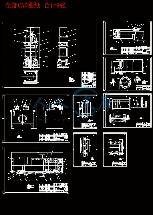
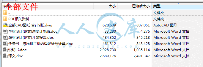
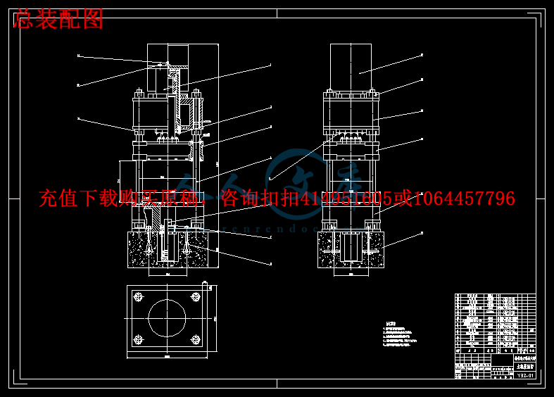
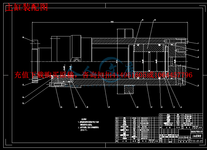
以下预览截图到的都有源文件,图纸是CAD,文档是WORD,下载后即可获得。


预览截图请勿抄袭,原稿文件完整清晰,无水印,可编辑

有疑问可以咨询QQ:414951605或1304139763

摘  要


根据任务书的要求,在设计前查阅了相关资料,了解了四柱式通用液压机的工作原理、设计过程,设计了一台四柱式通用液压机的主机部分。通过工作要求计算出液压机的主要技术规格,进行多种四柱式液压机的方案论证比较,选出了最优设计方案。根据最优方案,依次设计完成了液压系统、主机结构和泵站的设计计算。

液压机主缸是液压机的主要工作部件,液压机主缸的性能直接影响着液压机整体工艺水平。通过细致的分析及理论研究解决易损部分设计结构中存在的问题,可以使液压缸整体上达到工艺强度要求,提高液压缸应用的工艺水准及使用寿命。所以对液压机主缸进行细致严谨的设计计算对对液压机的设计生产有着至关重要的作用。

本论文从总体上对液压机本体结构,主要结构部件进行设计及必要的校核,对液压机主缸主要参数进行计算,并对所得结果进行分析、验算,从而力争使液压机主缸能够满足生产工艺要求,并从整体上提高液压机的工艺水准,使液压机设计水平更上一个新的台阶。

关键词:液压机;结构设计;液压缸

Abstract


According to the mission statement of requirements before designing the access to relevant information, to understand the working principle of universal four-column hydraulic machine, the design process, the design of a common host part of a four-post hydraulic press. Through the work required to calculate the main technical specifications of hydraulic machines, for a variety of four-column hydraulic machine demonstration program compares to elect the optimal design. According to the optimal solution, in order to complete the design of the hydraulic system, the host structure and pumping station design calculations.

Hydraulic master cylinder is the main working parts of hydraulic press, hydraulic press master cylinder direct impact on the performance of the overall technological level of hydraulic machines. Through careful analysis and theory to solve the structure vulnerable part of the design problems in it , and the hydraulic cylinder can be reached technological strength of the overall requirements of the application of technology to improve the standard of the hydraulic cylinder and life. So the cylinder for hydraulic design of meticulous

calculation of the design and production of hydraulic machines has a vital role.

This paper generally focus on the body structure of the hydraulic press, and design the major structural components and its necessary check , calculation of the main parameters of the hydraulic master cylinder, and analysis and checking the results. To strive to make the hydraulic master cylinder to meet the requirements of production press and raise the overall technological level of the hydraulic press, and hydraulic press design level to advance to a new level.

Keywords: Hydraulic press;Structural Design;Hydraulic cylinder


目    录


引言1

1  液压机的基本知识2

1.1 概述2

1.2 液压机的型号和主要技术规格3

1.2.1液压机的型号3

1.2.2液压机的主要技术规格3

1.3 液压机的分类5

1.4 液压机的发展概况5

2  四柱式通用液压机总体方案设计6

2.1 四柱式通用液压机的工作原理和动作循环分析6

2.1.1四柱式液压机的工作原理分析6

2.1.2四柱式液压机的动作顺序分析6

2.1.3四柱式液压机的工作循环分析7

2.2 主要技术规格的确定7

2.3 四柱式通用液压机的总体设计9

2.3.1四柱式液压机各部分的方案选择9

2.3.2总体布局设计9

3  四柱式液压机液压系统与电气系统设计10

3.1 液压系统设计10

3.1.1液压传动概述10

3.1.2液压系统设计参数10

3.1.3液压系统原理图的拟定11

3.1.4液压系统控制过程分析12

3.1.5液压元件的选择13

3.2 电气系统设计13

4  液压机主机结构设计与校核14

4.1 液压缸部件的设计与校核14

4.1.1液压缸的结构形式及方案论证比较14

4.1.2液压缸的支承形式及方案论证比较15

4.1.3柱塞与活动横粱的连接形式与方案论证比较16

4.1.4 液压缸基本尺寸计算16

4.1.5缸体强度计算17

4.2 顶出缸部件的设计与校核20

4.2.1顶出缸的尺寸计算20

4.2.2活塞杆稳定性的校核21

4.3 上横梁的设计与校核21

4.3.1上横梁结构形式及方案论证比较21

4.3.2上横梁的尺寸计算22

4.3.3上横梁的强度计算23

4.3.4上横梁的刚度计算23

4.4 工作台的设计与校核24

4.4.1工作台的结构形式与方案论证比较24

4.4.2工作台的尺寸计算24

4.4.3工作台的强度计算25

4.4.4工作台的刚度计算25

4.5 立柱组件的设计与校核26

4.5.1立柱的连接形式与方案论证比较26

4.5.2立柱的尺寸设计26

4.5.3立柱的强度校核27

4.5.4立柱螺母及预紧27

4.5.5立柱螺母的强度校核28

4.6 活动横梁的设计29

4.6.1活动横梁的结构设计29

4.6.2活动横梁尺寸设计29

4.7 主机其他部件设计30

4.7.1立柱导套30

4.7.2限程套30

4.8 主机总体结构设计31

5  液压机动力系统的设计与计算32

5.1 液压泵的计算与选择32

5.1.1液压泵最高工作压力的计算32

5.1.2液压泵最大流量计算32

5.1.3选择液压泵的规格33

5.2 电动机的选择33

5.3 油箱的设计与计算33

5.3.1油箱有效容积的确定33

5.3.2油箱的结构设计34

5.4 油管的设计与计算34

5.4.1主油缸油管内径计算35

5.4.2顶出缸油管内径计算35

5.5 泵站设备的布置36

5.5.1泵站设计应考虑的问题36

5.5.2泵站的结构形式设计36

6  四柱液压机安装调试和维护37

6.1 四柱液压机的安装37

6.2 四柱液压机的调试37

6.3 四柱液压机的保养维护38

7  结论38

谢辞39

参考文献40

附录41


引言

作为机械制造行业中一种重要的生产设备,锻压设备己广泛地应用于工业生产的各个领域。液压机作为一种通用的锻压设备,主要是利用液压传动技术实现各种压力加工工艺,具有功率大、精度高、规格多的特点。因此在锻压 (塑性加工)领域中,液压机被广泛应用于自由锻造、模锻、冲压(板料成形)、 挤压、剪切、拉拔成形及超塑性成形等工艺中。

本设计着重叙述了液压机的泵站、液压机的本体结构及设计计算以及液压机液压系统的设计三个方面,里面详细的说明了液压机的基本工作原理、特点、分类、基本参数、液压机的本体结构及其设计计算以及液压机的液压系统的设计,尤其主液压缸的设计与校核阐述了大量内容。

设计液压机的意义在于其不但具有较大的通用性,适用于塑性材料的成形如簿板件的落料、拉伸、压印等;轴类件的校正;零部件的压装;粉末制品的压制。还具有点动、手动和半自动等操作方式,可按工艺需要任选定时或定位控制,压力和行程可调,操作灵便、工作可靠。


1  液压机的基本知识

1.1 概论

液压机是根据帕斯卡原理制成,是一种利用液体压力能来传递能量的机器。在国民经济的各个领域都得到广泛的应用,如锻造液压机,模锻液压机、冲压液压机、万能液压机等。它们具有许多优点:如结构简单,结构布局灵活;可以根据工艺要求来灵活改变其压力与行程;可以根据工艺要求十分方便的在各种部位布置所需的液压缸;与机械压力机相比,具有压力和速度可在广泛的范围内无级调速;可在任意位置输出全部功率和保持所需压力;各执行机构动作可很方便地达到所希望的配合关系;振动小、易于实现计算机控制及自动控制等等。所以液压机在国民经济各部门得到了日益广泛的应用。
内容简介:
ADVANCES IN HYDROFORMING FOR MANUFACTURING AUTOMOTIVE PARTS Taylan Altan, Professor and Director Hariharasudhan Palaniswamy, Graduate Research Associate Yingyot Aue-u-lan, Graduate Research Associate Engineering Research Center for Net Shape Manufacturing (ERC/NSM) The Ohio State University, Columbus, Ohio 43210, U.S.A ABSTRACT Increase in demand for fuel efficient vehicles along with higher safety and environmental standards has forced automotive manufactures to look for increased applications of light weight materials such as Advanced High strength steel, Aluminum and Magnesium alloys and new manufacturing techniques to reduce the total weight of the car. Also, increased competition in market place has reduced the lead time for new models forcing automotive manufacturers to move towards new economical manufacturing methods to reduce the manufacturing cost. Hydroforming of sheet and tube is one of the new manufacturing methods currently being pursued by auto makers world wide because of a) low tooling cost, b) better properties (dent resistance and energy absorption) of part after forming, c) ability to form complex shapes and integrated structures (hydroformed tube may replace an assembly from several stampings) that reduces assembly cost and time. This paper provides an overview on the advances in press (machines) & tools, tests for material and lubrication selection and strategies for process design through FE simulation in sheet and tube hydroforming. Also, warm hydroforming of magnesium and aluminum alloys is briefly discussed. 1. INTRODUCTION Until recently hydroforming of sheet and tube was not considered for automotive manufacturing due its high cycle time. However, advances in hydraulics and intelligent press design over the time have reduced cycle time considerably making it attractive for automotive manufacturing. In addition, hydroforming of sheet and tube offers benefits such as a) low tooling cost, b) better properties (dent resistance and energy absorption) of part after forming, c) ability to form complex shapes and integrated structures (hydroformed tube may replace an assembly from several stampings). These reduce assembly cost and time thereby represent an attractive alternative to stamping in the current market trend towards smaller batch size of new models. Metal forming using liquid media is classified as shown in Figure 1. It is broadly classified into sheet and tube hydroforming depending on the input preform. Further, sheet hydroforming is classified into hydromechanical deep drawing and high pressure sheet hydroforming depending on the male or the female die that has the shape/impression to be formed. High pressure sheet hydroforming is further ntsclassified into hydroforming of single blank and double blank depending on number of blanks being used in the forming process. This paper provides an overview on the advances in press (machines) & tools, tests for material and lubrication selection and strategies for process design through FE simulation in all the areas of sheet and tube hydroforming. Also, warm hydroforming of magnesium and aluminum alloy sheet is briefly discussed. Tube Hydroforming (THF)Sheet hydroforming HydroMechanical Deep Drawing (HMD) High pressure sheet hydroforming Single blankDouble blank Metal Forming with liquid media Figure 1 Classification of the forming process using liquid media Schmoeckel et al 1999 2. TUBE HYDROFORMING (THF) 2.1. Description In THF, a tubular pre-form is placed between two dies. The dies are closed and held under pressure while the tube is internally pressurized and axially compressed to force the material into the die cavity to acquire the desired shape/impression of the die (Refer Figure 2). During this process, axial feed and internal pressure are controlled simultaneously to form the part without any defects such as bursting and wrinkling. THF process sequence; a) place a tube, b) seal and fill fluid, c) pressurize and feed material, d) take a formed part out THF System CTools /DiesAIncomingTubeDTool-WorkpieceInterfaceEDeformationMechanicsFEquipment /Environment / PressGHydroformedpartBBending /Preforminga) c) d) b) Figure 2 Schematic of the THF process and its process parameters nts Figure 3 Schematic of the hydroformed parts in an automobile Schroeder 1999 THF is now widely used in making tubular parts of different configurations used in automotive industry (Figure 3) and other applications such as appliances. The rapid growth of this technology has been due to the advantages THF offers compared to conventional manufacturing via stamping and welding namely; (a) part consolidation, (b) weight reduction through more efficient section design and tailoring of the wall thickness in structural components, (c) improved structural strength and stiffness via optimized section geometry, (d) lower tooling costs due to fewer parts, (e) fewer secondary operations (less welding and punching of holes during hydroforming), (f) tighter tolerances and reduced springback that facilitates assembly, and (g) reduced scrap since trimming of excess material is far less in tube hydroforming than in stamping. Schmoeckel et al 1999, Ahmetoglu et al 2000. In order to successfully design and develop a THF process or operation, improvements in each area of the THF technology and their interactions should be considered. The main components and key issues of a complete THF system (Figure 2) can be listed as follows: a) Quality of incoming tubes, b) Performing and bending design and production methods, c) Die and tool design guidelines, d) Die-workpiece interface issue (friction and lubrication), e) Deformation mechanics (metal flow) in different zone, f) Equipment, press and environment related issues, and g) Dimensions and properties of the hydroformed part. 2.2. Material properties/ Tubular Hydraulic bulge test We at ERC/NSM suggest tubular bulge test for determining the properties of tubular materials because a) stress conditions in THF are often biaxial similar to bulge test compared to uniaxial in the tensile test. The maximum effective strain achievable in the bulge test without local necking is much larger (usually twice) than that in the tensile test. Figure 4 shows the schematic of the bulge test for tubular materials. The tube held at the ends is subjected to internal pressure until it bursts. During the test the internal pressure and the height of the bulge are measured, which are used to obtain the flow stress of the material for process simulation. The burst height of the tube indicates the formability of the tube. The burst height from bulge test can be used as a indicator/ design specification for the quality of the incoming tubes to the THF plant Aue u- lan et al 2002. nts Figure 4 Schematic of tube bulge test to evaluate the material properties of tubes for THF Figure 5 Different zones of friction conditions in THF. 2.3. Lubrication selection In THF, depending on the deformation mechanism, the entire deformation area can be classified as guiding zone, transition zone and expansion zone. In guiding zone the tube is subjected to compressive axial stress due to feeding from either sides resulting in thickening of the tube and contraction of the surface of the tube on which lubricant is applied. In expansion zone the tube is subjected to biaxial tensile stress resulting in thinning and surface expansion. Transition zone mark the intermediate stage. Thus, a good lubricant in THF should be able to perform well in all the three zones. ERC/NSM has developed a) Guiding zone test b) Transition zone test and c) Expansion zone test emulating the deformation mechanism and the contact pressure in respective zones Ngaile et al 2004a, Ngaile et al 2004b to screen the commercially available lubricants for THF. 2.4. Press and Tooling THF press design plays a dominant role because it significantly influences the cycle time and the economics of the process. Figure 6 shows three basic press concepts for THF a) conventional design (long stroke design concept), b) new design (short stroke design concept), and c) similar to concept (b) without any locking mechanism. Among the basic concepts, concept (b) is used widely because a) it reduces cycle time with long stroke cylinder that is used mainly to move the top die up and down fast with less fluid pressure, b) Short stroke cylinder requires less volume of fluid to generate the required high pressure thereby reducing cycle time, and c) Mechanical locking of top die eliminates the high pressure hydraulic system for top die thereby reducing cost and making design more compact Siegert et al 1999, Osen 1999, Bieling 1999, Marando 2003 . Figure 7 shows the different types of presses available in the market that has adapted the three basic concepts. They basically differ in either the structure of press frame or typing of mechanical locking mechanism used. Figure 8 shows THF press with modular design concept. The benefits of this design are a) useful for a design that requires several step of production (performing hydroforming), and b) multiple ram can be locked together in order to form a large part Macrae et al 2003. nts Mechanical stoppersfor locking top die Short stroke cylinderrequiring high fluidpressure for lockingbottom die Short stroke cylinder requiring high fluidpressure for locking bottom dies Long stroke cylinder requiring less fluid pressure for moving top die Long stroke cylinder requiring high fluid pressure for locking Figure 6 Basic concepts of THF presses Breckner 1999 Figure 7 THF press types available in the market adapting the basic types Schnupp et al 2003 a) b)Figure 8 Modular press concept (Source: AP&T Schafer); a) single cell unit and b) double cell unit nts2.5. Process design through FE simulation Successful design of THF process requires the estimation of optimum relationship of the key process parameters; axial feed versus time and internal pressure versus time to form the part. More axial feed could result in buckling of the tube while less axial feed would result in leakage of the medium and also bursting due to excessive thinning. At ERC/NSM, FE simulation using PAMSTAMP 2000 coupled with optimization technique and adaptive simulation technique have been used to determine the loading path that results in minimum thinning and no wrinkling in the part and without any leakage of the medium during the process Jirathearanat et al 2004. Figure 9 shows the example optimum loading path obtained for hydroforming of a cross member part. Figure 10 shows the part geometry, die geometry and the thinning distribution in the part for the optimum loading path. Loading path estimated from FE simulations were used in experiments to form a good part (Refer Figure 11). 05001000150020002500300010203040506070Left Axial Feed (mm)Pressure (bar)01020304050607080RightAxial Feed(mm)Left Right Right axial feed Pressure #2 ( adjusted by experiment) Pressure #1 ( predicted by SF) Figure 9 Loading path obtained by adaptive simulation technique for forming cross member part. Crushed tubeLeft EndRight End (a)Hydroformed partMax. thinning Upper die Side segmented dies Calibrated part Lower die (c) (b)Figure 10 Schematic of the cross member part geometry, die geometry and the thinning distribution predicted by FE simulation for the optimum loading path at various stages nts PART #1 With pressure curve 1sttrial: wrinkled part PART #2 With pressure curve 2ndtrial: sound part, no wrinkle Wrinkle disappears Wrinkle Figure 11 Schematic of the part obtained from experiments using the estimated optimum loading path 3. HIGH PRESSURE SHEET HYDROFORMING AND VISCOUS PRESSURE FORMING 3.1. Description In high-pressure sheet hydroforming, the sheet is formed against female die by the hydraulic pressure of the fluid as shown in Figure 12. During the forming process, the intermediate plate acts as a blank holder to control the material movement from the flange and also seals the fluid medium to avoid leakage. Viscous pressure forming is similar to sheet hydroforming in which the pressure acting on the sheet is generated by compressing the viscous medium rather than hydraulic fluid/water in sheet hydroforming. The forming operation in high pressure sheet hydroforming can be divided into two phases. Phase I involves the free forming where the sheet bulges freely in the die cavity until it initiates contact with the die. This introduces uniform strain distribution throughout the sheet thereby a) The formability of the material is effectively used compared to conventional stamping process where deformation is localized in the sheet at the punch corner radius, and b) Improves the dent resistance of the hydroformed part compared to stamped part. Phase II involves calibrating the sheet against the die cavity to obtain the desired shape. High fluid pressure is required in phase II depending on the material, sheet thickness, and the smallest corner radius in the die geometry. Thus, sheet hydroforming offers a viable alternative process for fabricating automotive parts from low formability advanced high strength steels and aluminum alloys. nts Initial state Phase I Phase II Figure 12 Schematic of the high pressure sheet hydroforming process Kleiner 1999 Successful application of high pressure sheet hydroforming requires careful consideration of all components of high pressure sheet hydroforming system namely: a) Quality of incoming sheet, b) Die-workpiece interface issue (friction and lubrication), c) Tool design for efficient application of BHF and avoid leakage d) Relationship between the internal fluid pressure and blank holder force (loading path), e) Press and tooling, and d) Dimensions and properties of the hydroformed part. 3.2. Material properties/Viscous pressure bulge test We at ERC/NSM suggest bulge test (Viscous Pressure Bulge test, VPB test) for determining the properties of sheet materials and to check the quality of sheets incoming to the stamping plant because a) Stress conditions in stamping/ sheet hydroforming are often biaxial similar to bulge test compared to uniaxial in the conventional tensile test, b) The maximum effective strain achievable in the VPB test without local necking is much larger (usually twice) than in the tensile test. Figure 13 shows the schematic of the bulge test where the sheet clamped at the edges is bulged freely by the viscous pressure until it burst. During the test, the height of the dome and the internal pressure of the viscous medium are measured in real time. The measured dome height and pressure are used as an input to the inverse analysis using FE simulation to determine the flow stress of the material. The burst dome height is a good indicator of the formability of the material (The higher burst dome height the better formability). Also, the burst dome height can be used as a indicator/ design specification to check the quality of the incoming material to the stamping plant Gutcher et al 2000. nts Continuously measured dataPressure (P)Dome height (h)FEM Simulationsdatabase Dome profile (Curvature)Thickness distributionEffective stress += 121ddtrpEffective strain =01lnttdMembrane Theoryy = 558.56x0.2212R2= 0.97260.0100.0200.0300.0400.00.000 0.040 0.080 0.120 0.160True strain (mm/mm)Truestress (MPa)0200004000060000Truestress (Psi)Experimental dataPower law fit curvePotentiometer Upper Die Viscous Medium Pressure Transducer Lower Die Cushion Force a)VPB test tooling b) Procedure to calculate the flow stress from VPB test Figure 13 Schematic of the VPB test tooling and method to determine the flow stress 3.3. Lubrication selection Lubrication plays a dominant role in controlling material flow in the blank holdersheet and the die-sheet interface during forming process. Failure of lubrication results in a) excessive thinning resulting in tearing of the part, b) excessive galling resulting in damage of surface finish of the formed part and c) wear of the dies. Lubricants used in sheet hydroforming usually fail due to high contact pressure at material-die interface. The pressure generated at the interface depends on the material, sheet thickness and the die geometry. Thus a single lubricant cannot satisfy the requirements of all the processes. Selection of lubricants should be made using tests that emulate the interface pressure, surface expansion close to production conditions. ERC/NSM suggests use of Stamping Lubricant Tester (SLT) Yadav et al 2004 and Modified Limiting Dome height test Schneider et al 2003 for screening commercially available lubricants for sheet hydroforming process. 3.4. Press and tooling 3.4.1. High pressure sheet hydroforming press High pressure sheet hydroforming presses and tools are designed and manufactured based on the technology developed and available in THF. However, in sheet hydroforming, higher clamping force due to large area of the sheet and blank holding mechanism need to be considered. University of Dortmund, (LFU), Germany in cooperation with Siempelkamp PressenSysteme (SPS), Germany had built a 10,000 ton press for high pressure sheet hydroforming of large automotive parts (Figure 14). The press is designed to have horizontal mounting for inexpensive compact design, easy handling of workpiece, short stroke for cylinder to reduce cycle time and requires less investment for foundation in the shop floor. The press frame is cast and ntsprestressed by wire winding to withstand dynamic load during forming. During hydroforming, large volume of fluid at relatively less pressure is required during the phase I (free bulging) and small amount of fluid at high pressure is required in phase II for calibration. Hydraulic systems in the press were designed at two different pressure levels a) max pressure of 315 bar with volume of 100 liter of pressurizing media and b) max pressure of 2000 bar with volume of 5 liter of pressuri
温馨提示:
1: 本站所有资源如无特殊说明,都需要本地电脑安装OFFICE2007和PDF阅读器。图纸软件为CAD,CAXA,PROE,UG,SolidWorks等.压缩文件请下载最新的WinRAR软件解压。
2: 本站的文档不包含任何第三方提供的附件图纸等,如果需要附件,请联系上传者。文件的所有权益归上传用户所有。
3.本站RAR压缩包中若带图纸,网页内容里面会有图纸预览,若没有图纸预览就没有图纸。
4. 未经权益所有人同意不得将文件中的内容挪作商业或盈利用途。
5. 人人文库网仅提供信息存储空间,仅对用户上传内容的表现方式做保护处理,对用户上传分享的文档内容本身不做任何修改或编辑,并不能对任何下载内容负责。
6. 下载文件中如有侵权或不适当内容,请与我们联系,我们立即纠正。
7. 本站不保证下载资源的准确性、安全性和完整性, 同时也不承担用户因使用这些下载资源对自己和他人造成任何形式的伤害或损失。
提示  人人文库网所有资源均是用户自行上传分享,仅供网友学习交流,未经上传用户书面授权,请勿作他用。
关于本文
本文标题:液压机主机结构设计与计算【9张CAD图纸+毕业论文】【答辩优秀】
链接地址:https://www.renrendoc.com/p-473137.html

官方联系方式

2:不支持迅雷下载,请使用浏览器下载   
3:不支持QQ浏览器下载,请用其他浏览器   
4:下载后的文档和图纸-无水印   
5:文档经过压缩,下载后原文更清晰   
关于我们 - 网站声明 - 网站地图 - 资源地图 - 友情链接 - 网站客服 - 联系我们

网站客服QQ:2881952447     

copyright@ 2020-2025  renrendoc.com 人人文库版权所有   联系电话:400-852-1180

备案号:蜀ICP备2022000484号-2       经营许可证: 川B2-20220663       公网安备川公网安备: 51019002004831号

本站为文档C2C交易模式,即用户上传的文档直接被用户下载,本站只是中间服务平台,本站所有文档下载所得的收益归上传人(含作者)所有。人人文库网仅提供信息存储空间,仅对用户上传内容的表现方式做保护处理,对上载内容本身不做任何修改或编辑。若文档所含内容侵犯了您的版权或隐私,请立即通知人人文库网,我们立即给予删除!