毕业论文.docx

圆柱螺旋弹簧测力分选机结构设计【10张CAD图纸+毕业论文】【答辩优秀】

收藏

压缩包内文档预览:(预览前20页/共46页)
预览图 预览图 预览图 预览图 预览图 预览图 预览图 预览图 预览图 预览图 预览图 预览图 预览图 预览图 预览图 预览图 预览图 预览图 预览图 预览图
编号:473197    类型:共享资源    大小:3.74MB    格式:RAR    上传时间:2015-08-17 上传人:好资料QQ****51605 IP属地:江苏
45
积分
关 键 词:
圆柱 螺旋弹簧 测力 分选 结构设计 全套 cad 图纸 毕业论文 答辩 优秀 优良
资源描述:

目录

摘要.........................................................I

Abstract....................................................II

第1章 绪论.................................................4

1.1 课题研究目的及意义....................................4

1.2分选机分选方式研究....................................6

1.3课题国内外现状.........................................6

  1.3.1国外分选机研究现状..................................6

 1.3.2国内分选机研究现状.................................. 7

1.4存在问题...............................................7

第2章 方案的选择与设计..................................9

2.1本课题的设计任务.......................................9

2.2圆柱螺旋弹簧分选机的设计思路..........................9

2.3送料机构..............................................10

2.4加力与检测机构........................................11

2.5落料分选机构..........................................12

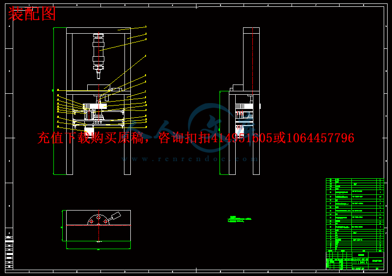
第3章 总体的机构设计...................................14

第4章 弹簧分选机零件结构设计.........................16

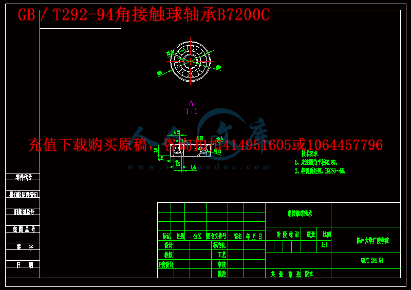
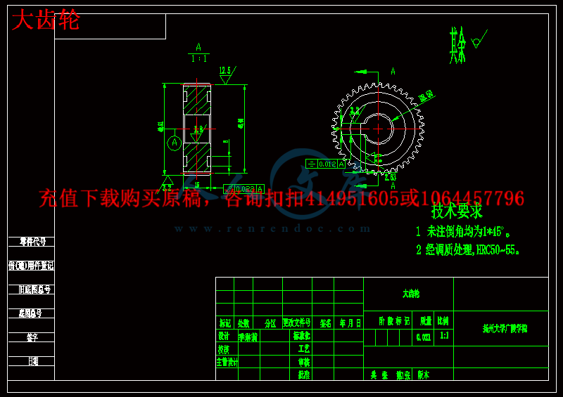
4.1齿轮的选择设计........................................16

4.2夹持轴承与轴的连接的夹具的选择.......................17

4.2.1上夹具的设计.......................................17

4.2.2下夹具的设计.......................................19

4.3气缸的设计选择........................................20

4.4传动轴的选择设计......................................22

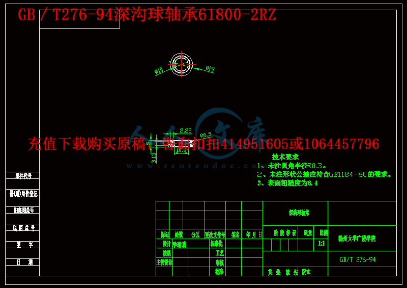
4.5轴承的选择设计........................................24

4.5.1原动部分装配所选用的轴承...........................24

4.5.2 执行部分装配所选用的轴承..........................26

4.6其他主要零部件的设计.................................28

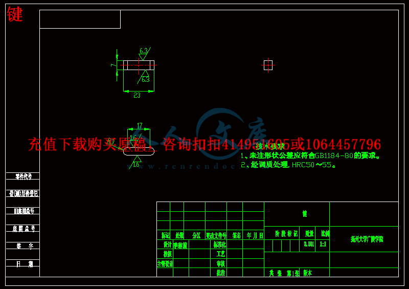
4.6.1键的选择设计.......................................28

4.6.2轴套的选择设计......................................28

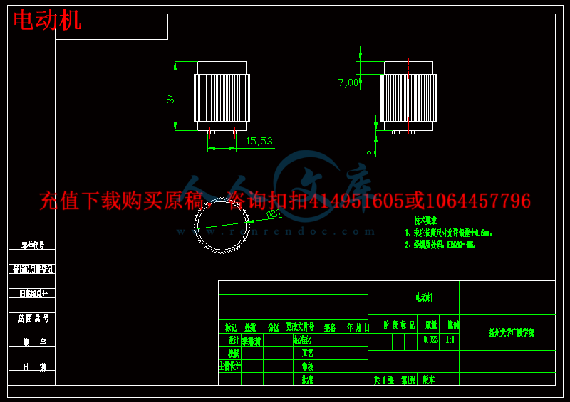
4.6.3电动机的选择设计...................................29

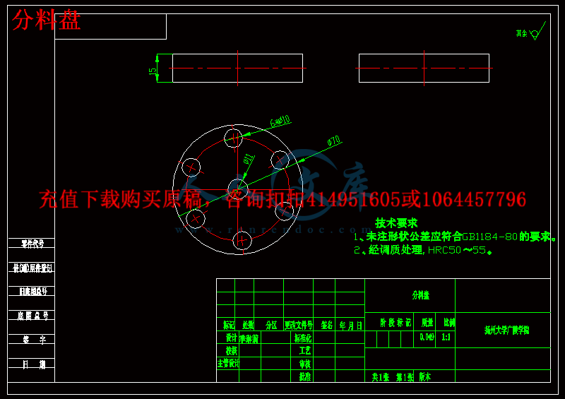
4.6.4分料盘的设计.......................................31

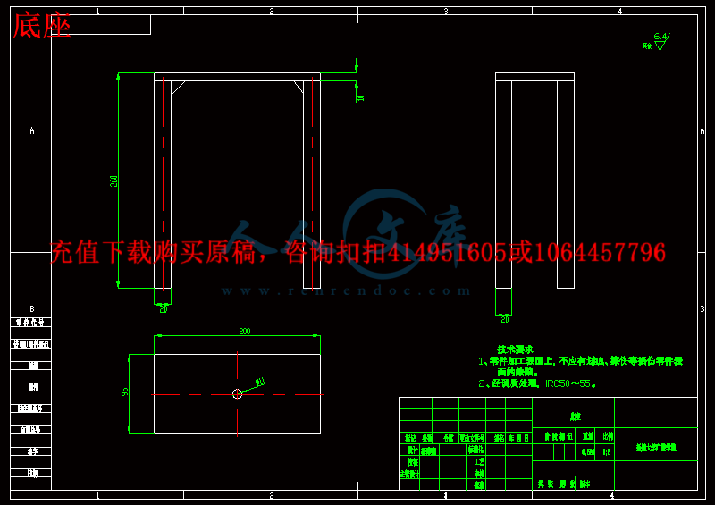
4.6.5底座的设计................................ 32

第5章 校核计算..................................34

5.1底座上板的受力分析与弯曲应力计算...................34

5.2 轴受力分析与应力计算.............................. 36

总结............................................39

致谢............................................41

参考文献........................................42

附录............................................43


摘 要

弹簧的应用十分广泛可以说是各种机械、电器 、化工等产品的关键零件。凡是承受变载荷的弹簧,在企业内部质量控制、用户交验、新产品定型鉴定、认证,行业抽检和工艺调整环节中,必须进行性能检测。所以弹簧检测是其生产过程必不可少的工序,测力是检测的主要内容之一。弹簧测力分选机是在基于工业进程高速发展的今天,结合圆柱螺旋弹簧的需求量和生产企业需求的前提下所应运而生的。本论文主要是对分选机的机械结构进行研究,设计,实验与制造。

此弹簧分选机是针对大批量生产的弹簧依据其弹性系数不同,按照预先规定的指标进行测试自动筛选出合格与不合格产品,并在不合格产品范围内依据是否可以修复将弹簧进一步细分,自动流入不同料箱,以此应用与不同场合。这种弹簧分选机是安装在弹簧加工过程中的检测工艺工段线上,针对汽车、摩托车离合器弹簧生产制造工艺设计的,适用于各种类型的圆柱螺旋弹簧的分选。

本论文首先论述螺旋弹簧分选机的分选方式以及国内外分选机的研究现状和设备的性能优缺点,结合课题背景,提出本论文的主要研究内容。在对弹簧特点与控制需求进行分析的基础上,提出了分选机机械结构的方案设计。

在论文中所研究和设计的圆柱螺旋弹簧分选机,满足功能要求,解决了弹簧生产过程中的实际问题,提高了生产与检测效率,为以后此类设备的设计提供了借鉴作用。


关键词:圆柱螺旋弹簧; 分选机; 弹性系数


Abstract

Spring testing is the phase of the production process essential working procedure, load is one of the main content of detection. Spring load separator is in today's rapid development based on industrial process, in combination with the demand and production of cylindrical helical spring under the premise of enterprise requirements arises at the historic moment. This thesis mainly is the study of mechanical structure of the separator, the design, the experiments and manufacture.

 This spring sorting machine is for mass production according to the elastic coefficient of the spring, in accordance with the prescribed index test automatically select the qualified and unqualified products, and within the scope of the unqualified products according to whether can repair will spring further subdivided, automatic into the different material box, with different situations in application. The spring separator is installed in the spring section of online detection technology, in the process of machining for automobile, motorcycle clutch spring manufacturing process design, suitable for various types of cylindrical helical spring sorting.

 This paper first expounds the separation method of helical spring sorting machine and the performance of the domestic and foreign research situation of the separator and equipment advantages and disadvantages, combined with the project background, puts forward the main research content of this paper. On the analysis of the demand and control characteristics of the spring, on the basis of sorting machine mechanical structure design are put forward.

  In the thesis the research and design of cylindrical helical spring sorting machine, meet the functional requirements, solved the practical problems in the process of producing spring, improve the efficiency of the production and testing, design provides a reference for such a facility.


Keywords: Cylindrical helical spring; separator; Modulus of elasticity


第1章 绪论

1.1 课题研究目的及意义

  弹簧的应用十分广泛,可以说是各种机械,电器,化工等产品的关键零件。近几年来,国内弹簧工业的设计制造及材料方面有了新的发展,对弹簧的要求也越来越高,在各种螺旋弹簧中,内燃机的气门簧是其中较为重要的弹簧之一,它是国家质监部门要求负荷值全检的产品,装入内燃机的每一只气门簧,都必须经过数字检测设备的严格检测,这样才能保证内燃机工作的可靠性与寿命。由于内燃机气门弹簧种类繁多,数量巨大。因此,用普通的手动检测设备进行检测,由人进行分类的方法,容易产生许多误操作使得供,需双方发生许多的摩擦与误会并且工作量也是十分巨大的。因此,各弹簧生产厂及主机厂均希望能拥有一种能在线进行检测并能自动进行分类的设备——弹簧分选机,但是,目前国内市场上能见到的弹簧分选机均为国外厂家生产的,这些分选机不但分组单一,且价格昂贵。国内各弹簧生产设备及检测设备生产厂均未研制出高效实用的弹簧分选机。国外市场上能见的分选机类型为两种——高精度型和高速度型;高精度型弹簧分选机主要用来分选那些精度要求很高的弹簧,但这种分选机的分选速度很低,不适合大批量弹簧生产的需要。高速度型弹簧分选机在速度上能达到较高的要求但价格非常昂贵。国内很多弹簧生产机检测设备生产厂针对各自的需求研发了一些弹簧分选机设备,如基于重力的弹簧分选机,基于尺寸的弹簧分选机,基于压力的弹簧分选机,这些设备在功能和性价比上都还和国外同类产品有一定差距。

内容简介:
以 LabVIEW 为合成橡胶弹簧试验机的液压控制 博 尔达 王 旭永 (机电研究所,上海交通大学,上海, 200030,中国) 摘录: 该应用程序是一个液压缸同步运动控制运动。 本文的主要目的是显示一个短的编程代 码中的 LabVIEW 来控制两个气缸与自动控制程序仅使用从压力传感器和线性位移传感器的模拟输入和从所述液压阀的数字输出的运动 。 这是专为这种合成橡胶弹簧试验机的试验之一。 关键词: 橡胶弹性;多层橡胶弹簧; 层叠式顺序结构 文献标识码: A 简介 合成橡胶试验机是检测 地铁车 的 橡胶弹簧。实际使用这台机器是为了使预防维护,这样我们就可以准确了解橡胶弹簧 的 消费生活。每一个橡胶弹簧是一种周期 或工作时间的主题,这一时期的弹簧橡胶测试必须根据制造商的规格 ,这种试验机是被用来测试四种橡胶弹簧; 用于此测试的一个是所谓的多层橡胶弹簧。本试验的主要特征,与其它橡胶弹簧相比,是 , 这是结合了两个气缸的力 成为唯一 一个:一个垂直和一个水平。 1. 结构 组件 这种 试验机的结构组件是非常简单的。该测试平台具有上框架,移动框架,下框架,装框架试件垂直柱,卡盘框架支撑上的工作平台,液压系统安装下至工作平台。 该平台最高液压为 150KN,它是 一个简单的机械结构,只 需 使用两个垂直列来 支持 它。同时,这个设计是在 多层橡胶弹簧元件的刚性横向测量条件下。此外, 也 有不同的试件,测量是不一样的。 这种 卧式液压缸 是固定到 框架结构 里的 。该基地的高度可以 通过 试验件 根据 试验只是改变底座支 撑来 修改。 它的垂直压力传感器被固定在垂直圆柱 的头部。 垂直缸的运动总是向下推施加压缩力成试片。垂直传感器被安装在底 框结构中的一个固定 位置正好平行于垂直列。垂直力传感器被安装在垂直缸的头部的基极,水平位移传感器安装在水平筒的右侧的 这个底部(查看图 1)的背面。 一个多层橡胶弹簧的弹性试验期间,水平力必须申请 65 kN 然后水平缸必须 移位 土30 毫米,在这个过程中,我们获得了从模拟信号的水平缸的力传感器,然后我们要衡量的橡胶弹簧常数 K 为使用此公式 K =( F1 + F2) / 60(牛顿 /毫米) 的这个原因 。 nts 图 1 试验机的概貌 1-上部框架; 2-垂直缸; 3-移动框架; 4-垂直力传感器; 5-力柱; 6-垂直位移传感器;7-试件; 8-工具板; 9-下部框架; 10-组件框架; 11-水平力传感器; 12-卧式圆筒; 13-水平位移传感器 2.压力系数 压力系统的原理可以被视为在图 2系统使用两个液压泵连接电机, 所述液压泵不超 16兆帕,6 毫升 /转 和 16 毫升 /转流的工作压力。泵站设计有一个压力表计,过滤器等 。 泵的工作压力(水平和垂直气缸)是通过 四个 电磁阀分开。泵 1 被设计为三个不同的工作压力( 150,100,50 KN)。因此,为测定试验高频即 液压泵的速度可以用一个阀门来调节。 试验加载速度约为 1mm/s,这也是在卸载工艺流程 中。速度可以调整 到 大约 2mm/ s,系统具有两个阀 来 关闭 , 这些 也 是用于保护液压泵。液压系统的示意图,可以理解在图 2 中,电磁阀的控制和改变可以在表 1 可 以 看 出 。nts 图 2 液压原理图 1,2,3,4-减压阀; 5,6-电磁整流阀; 7,8-单向收缩药; 9-流量控制的单向阀,电磁阀; 10,11,12-整流器; 13-单向阀; 14-闸阀 ; 15-过滤器; 16-压力计; 17-空气滤清器 表 1 液压系统动作图 标准态 主缸快速前进 主缸缓慢 前进 主缸缓慢 返回 主缸快速 返回 卧式液压缸左 前 进 卧式液压缸 右前 进 主缸液压 1 主缸液压 2 主缸液压 3 nts 3.采集卡和驱动控制 对于数据的控制和采集我们使用了两个不同的卡: 一个模拟卡收集从传感器的信号以及另一个收集数字卡控制的开关阀信号 。 这两种卡是研华卡,这些卡都是台湾制造,他们也控制使用 LabVIEW,该驱动程序的 LabVIEW 必须下载从 Advantechl 公司的网站。 这种 模拟卡是 由PCL 818 L16 路单端或 8 路差分模拟量输入, 40 千赫 ,12 比特 的 A/ D 转换器(转换时间 25 微秒)。 可编程增益 对于 每个输入通道(最多 8 个)与 DMA 的自动通道 /增益 进行 扫描。 这种数字 I/O 卡有 32 个隔离的 PCL-730 DIO 信道( 16 个 输入和 16 个 输出),硬件结构,你可以在图 3 看出 。 显示屏 模拟传感器 PCL818LS 控制计算机输出 16 频 A/D PCL730(I/O 16 频 ) AVDAM3920 ADAM3920 数字输入 24 伏 4 频 AVDAM3920 AVDAM3920 数字输出 数字输出 24 伏 4 频 24 伏 4 频 图 3 硬件系统结构 4.控制程序的编程 一旦我们安装驱动程序为研华卡 程序可以启动。 该 程序的配置是以 LabVIEW 为它显示在图 4的一种基本的控制。 垂直圆柱体 最后阶段 开始阶段 第二阶段 第三阶段 第一阶段 卧式圆筒 初始点 nts图 4. 气缸的控制过程视图 在开始阶段,垂直气缸压缩橡胶弹簧,到它检测的 65 千牛的力,然后卧式筒体必须 移动 + 30 毫米到右侧,然后返回到左边 -60mm 的,然后移动到右边 +30 毫米和停止,和垂直气缸回到它原来的点(图 4 看到)。 在这个组合过程中的难点之一是控制运动,因为这种运动必须同步,以避免两个油缸碰撞。 在这种情况下,我们将只显示气缸控制由于这个 程序的完全控制,也扩展到本报告 中表 明我们也只会显示背面板程序控制测试。这 LabVIEW 程序主要是通过使用所谓的层叠顺序结构的元件,该元件由一个或更多的子图或帧,即按顺序执行设计的。 使用堆叠式顺序结构 以 确保 一个子图的 另一个 子图的之前或之后执行。 4.1 起步阶段 你可以在图 5 中看到,在第一阶段,在当垂直圆筒下来 直到垂直力传感器获得的力 65KN 相对于橡胶弹簧则气缸停止,并保持在这个位置,直到测 试完成时(参见图 4)。 4.2 第一阶段 对于水平缸的控制, 我们必须首先使用 水平位移传感器 获得初始位置 ,然后我们可以标记在这个初始点我们的起点和基础,可以使我们的位移与气缸数 有 + 30 毫米( 查看 图 6) 的 控制。 4.3 第二阶段 在第二阶段的水平气缸的返回必须扩展 - 60mm 到左 侧 然后停止,在这个过程中,我们必须取得气缸施加在橡胶弹簧(参见图 7)力的测量。 4.4 第三阶段 在第三阶段,气缸必须返回 +30mm 到右边,然后停止到 原始点(第一阶段)(参见图 8)。 4.5 最后阶段 一旦水平气缸已经返回到原始点(第一阶段)并且 程序已关闭水平圆柱所有的阀门,然后垂直油缸必须开始工作。在这种情况下,垂直气缸使用的垂直位移传感器,使气缸回到原来的工作点,但在开始时,因 为我们需要控制施加到弹簧橡胶的力,我们必须使用 力传感器来做到这一点(参见图 9)。 nts 图 5.立式汽缸 的开始阶段 图 6.卧式气缸的 第一阶段 nts 图 7.卧式气缸的第二阶段 图 8.卧式气缸的第三阶段 nts 图 9.立式气缸的最后阶段 堆叠的序列结构为多帧序列 , 以便序列 的运行 ,我们用 10 序列 在 该程序过程中从 0 到 9;在这篇报告中我们只显示主要的阶段,对于 介质 阶段主要是控制阀门最后阶段 的关闭 。这是因为我们使用的是阀的通断阀和保留的最后一个进程的内存,所以我们必须小心,当我们利用堆叠顺序结构 来编程的时候 。 例如,你可以看到图 10, 这表明 最后 阶段 9 是当垂直缸停在初始点 时 。 图 10.立式气缸的最后一帧 从水平位移传感器和水平力传感器获得的信号被用于绘制使用该橡胶弹簧的弹性的曲线,在测试过程中,我们可以测量橡胶弹簧的常数 k。 这让我们知道生命周期的同事也让我们知道了橡胶弹簧的情况,为了能够对这个程序有个清晰的理念,我们可以查看 图 11, 如你所见, Fy,是水平方向的力信号( KN)和施水平位移信号(毫米), F1 和 F2 分别是第一和第二级的测量结束时获得的最终的力。 在程序的最后阶段能够告诉我们 多层橡胶弹簧的状态,你可以在图 12 中看到 nts 图 11.橡胶弹簧的试验过程中的数据 . 图 12. 应用程序数据的橡胶弹性曲线最后的基址图 5.总结 虚拟仪器软件 LabVIEW 被用来 液压缸的控制程序。这是一个简单而可靠的软件 ,而无需使用 编码程序来做这个。我们必须注意,唯一的问题是有图书馆的采集卡,我们要使用,如果这些都不是 NI 控制卡采集卡。这台机器的发展有助于我们做出预防保养。控制的元素都不难获得,但该软件可能是一个艰难的一步 来完成它 。 但是,使用 LabVIEW 这 步是 简单的一步 。 LabVIEW 的 其中一个 优势 就 是在工作中可以 以 一种直观的方式 看出 ,当我们使用 Visual看到并纠正程序中的任何错误 时 ,不 需要 调试主要代码 C + +或其他编程语言。 参考文献 【 1】 艾斯克 J. 高级视 图试验【 M】 . 纽约州,美国; Prentince Hall 出版社 .1999。 【 2】 理查德 , 马特, Lab VIEW: 高级编程技术 M。第二版博卡拉顿: CRS 出版社, 2001。 【 3】 王雄冰,王旭勇,谢文华。发展橡胶弹簧综合测试床研究 J。电力机车与城轨车辆,2003,26( 6) :41-43。 nts【 4】 王雄兵,王煦 勇, 橡胶弹簧的 数据测试和资料分析 J, 电力机车大众运输车辆,2003,26( 4): 56。 参考文献 【 1】 刘 CR,米塔尔 S,单步超精加工硬切削:可行性与可行的切削条件研究 J。机器人计算集成制造, 1995,12( 1) :15-27。 【 2】 顿肖夫 , 阿伦特 C,阿莫尔 R B.切削淬硬钢 J。 机械工程研究所 的活动年报 ,2000,49( 2) ; 547-566。 【 3】 刘 CR。米塔尔 s.单步执行 超精加工用硬质加工造成表面完整性 研究 上 。 J 制造系统, 1995,14( 2): 124-133。 【 4】 瑞希,梅森, 表面完整性的情况下完成硬车削淬硬钢 J。国际机床 与 制造学报,2003,43( 3): 543-550 【 5】 阿布拉 AM, 阿斯平沃尔 DK. 集体的表面完整性的车削和磨削淬硬轴承钢 J。磨损,1996,196( 2): 279-284。 【 6】 周 YK, 伊万斯 C J。白层和硬车削表面的热建模 研究 J。国际机床与 制造学报,1999,39( 2): 1863-1881。 【 7】 Sasahara H, Obikawa T, T 有限元分析切削加工层 J, 力学特性的影响 J。序列,材料的专业技术公司。 1996.62( 4): 448-453。 【 8】 雅各布森 M,达尔曼 P, 冈恩 F。切割速度的影响 在 硬贝氏体钢表面完整性的研究J。材料科技, 2002,128( 3) :318-323 【 9】 杨 文华 , Tarng Y S, 设计优化车削操作的基于田口方法 J, 切削参数。难加工材料的加工技术, 1998,84( 1): 122-129。 ntsJournal of Shanghai Jiao tong University ( Science ) , Vo 1 E 一 10, No .4 , 2005 , 381386 Article ID: 1 007 11 72( 2 0 05) 0 4 03 81 - 06 The Hydraulic Control Using LabVIEW for a Synthetic Rubber Spring Testing Machine Alejandro Borda( 博 尔达 ) , WANG Xu yong ( 王 旭永 ) ( Mechatronic Inst , Shanghai Jiaotong Univ , shanghai 200030, China ) Abstract: The application is a control movement of two hydraulic cylinder for a synchronize movement. The main purpose of this paper is to show a short programming code in LabVIEW to control the movement of two cylinders with an automatic control program using only analog inputs from the sensor of pressure and linear displacement sensor and the digital output from the hydraulic valves This is designed for one of the test of this synthetic rubber spring testing machine Key words: rubber elasticity; multi layer rubber spring; stacked sequence structure Document code: A Introduction The synthetic rubber test machine is to test the rubber spring of the subway wagon The practical use of this machine is to make a preventing maintenance so we can know with accuracy the spending life of the rubber spring Every rubber spring is a subject of a cycle or working hours, after this period the testing of this spring rubber must do it according to specification of the manufacturer, the testing machine is designed to test 4 kinds of rubber springs; the one that is used for this test is called multi layer rubber spring The main characteristic of this test,compared with the other rubber springs, is that this is the only one which combines the force of two cylinders: one vertical and one horizontal. 1. Structure Assembly The structure assembly for the testing machine is very simple The testing platform has an upper frame, mobile frame, lower frame, test piece vertical column of a chucking frame,chucking frame support upper of the working platform, hydraulic system is installed down to the working platform The platform highest hydraulic pressure is 150 KN , and a simple mechanical structure only uses two vertical columns to hold it At the same time the design is under the consideration of the rigid transversal measurement of the multilayer rubber spring elements Moreover, there are different test pieces and the measurements are not the Same The horizontal hydraulic cylinder is fixed into the frame structure The altitude of the base can be modified according to the testing piece just changing the base support according to the test. The vertical pressure sensor is fixed at the head of the vertical cylinder The movement of the vertical cylinder is always pushing down applying a compression force into the testing piece The vertical sensor is installed at the bottom frame structure in a fixed position just parallel to the vertical columns The vertical force sensor is installed at the base of the head of the ntsvertical cylinder and also the horizontal displacement sensor is installed at the back of the horizontal cylinder right at the bottom of this ( View Fig.1 ) During the elasticity test of a multi layer rubber spring, a horizontal force must be apply to 65 KN and then the horizontal cylinder must displace 土 30 mm, during this process we acquire the analog signal from the force sensor of the horizontal cylinder, then we have to measure the constant K of the rubber spring for this reason using this formula K=(F1+F2) 60(N mm) Fig.1 General view of the testing machine 1-Upper frame; 2-Vertical cylinder; 3-Mobile frame; 4-Vertical force sensor; 5-Force column; 6-Verticl displacement sensor; 7-Test piece; 8-Tool plate; 9-Lower frame; 10-Assembly frame;11- Horizontal force sensor; 12-Horizontal cylinder ; 13-Horizontal displacement sensor 2. Pressure System The pressure system principles can be seen as in the Fig .2 The system uses two hydraulic pump connected with an electrical motor, the hydraulic pumps never exceed the working pressure of 16 MPa, a flow of 6 ml/r and 16 ml/r The pump station is designed with a pressure gauge meter, filter etc The pumps working pressure(horizontal and vertical cylinder)is divided through four electromagnetic valves The pump 1 is designed for three different working pressure(150,100,50 KN).Therefore for the high frequency of measurement test the speed of both hydraulic pumps can be adjusted using a valve During the loading test the speed is about 1mm s, this is also during the unloading process The speed can be adjusting around 2mm s; the system has two close valves these are for protecting the hydraulic pumps. The schematic of the hydraulic system can be appreciated in the Fig.2 and the control and change of the electromagnetic valves can be seen in Tab.1 nts Fig.2 Hydraulic pressure diagram 1, 2, 3, 4 一 Pressure relief valve; 5,6 一 Electromagnetic commute valves; 7, 8 一 One way re strictor; 9 一 Flow control one way valve; 10, II, I2 一 Electromagnetic commute valves;I3 一 One way valve; 14-Gate valve; 15 - Filter; 16-Pressure gauge; 17 一 Air filter Tab 1 Action chart of the hydraulicsystem Standard state Main cylinder fast advanced Main cylinder slow advanced Main cylinder slow return Main cylinder fast return Horizontal cylinder left advanced Horizontal cylinder right advanced Main cylinder hydraulic pressure I Main cylinder hydraulic pressure2 Main cylinder hydraulic pressure3 3. Acquisition Card and Control Drivers For the control and acquisition of data we use two different cards: one analog card to collect the signal from the sensors and the other digital card to control the on off valves. Both cards are advantech cards, these cards are made in Taiwan and they are also controllable using LabVIEW, the drivers for LabVIEW must be downloading from the Website of Advantechl Company. The ntsanalog card is the PCL 818L 16 singleended or 8 differential analog inputs, 40 kHz, 12-bit A/D converter (conversion time 25 s) Programmable gain for each input channel(up to 8 )Automatic channel/gain scanning with DMA The Digital I/O card is PCL-730 which has 32 isolated DIO channels(16 inputs and 16 outputs), the hardware structure you can appreciate in Fig.3 Fig.3 The hardware system structure 4. Programming of the Control Program Once we install the drivers for the advantech cards the program can start. The configuration of the program is a basic control using LabVIEW as it shows in Fig.4 At the beginning stage the vertical cylinder compresses the rubber spring until it senses a force of 65 KN then horizontal cylinder must start moving + 30 mm to the right and then return to the left-60mm and then move to the right+ 30 mm and stop, and the vertical cylinder returns to its original point(view Fig.4) During this combination process one of the difficulties is the control movement because this movement must be synchronized to avoid both cylinders colliding In this case we are going to show only the control for the cylinders because the full control of this program is too extended to show it in this report also we are only going to show the back panel program to control this test This LabVIEW program is mainly designed by using the element called stacked sequence structure which consists of one or more sub diagrams, or frames, that execute sequentially Use the stacked sequence structure to ensure a sub diagram executes before or after another sub diagram Fig 4 View of the control process of the cylinders 4.1 Beginning Stage As you can see in Fig.5,at the first stage when the vertical cylinder is coming down until the vertical force sensor acquire 65kN of force against the rubber spring then the cylinder stops and stays in this position until the test is completed(See also Fig.4) 4.2 First Stage For the control of the horizontal cylinder, first we have to acquire the initial posit using the horizontal displacement sensor, and then we can mark our initial point and base on this initial point and can make our displacement and control of the cylinder counting + 30 mm (View Fig.6 ) 4.3 Second Stage During the second stage the return of the horizontal cylinder must extend -60mm to the left and then stop ,during this process we must acquire the measurement of the force that the cylinder exerts over the rubber spring(See Fig 7) 4 .4 Third Stage In the third stage, the cylinder must return + 30mm to the right and then stop to the original point( first stage )( See Fig 8) 4 .5 Final Stage nts0nce the horizontal cylinder has returned to the original point(First Stage)and the program has shut off all the valves of the horizontal cylinder and then the vertical cylinder must start working In this case, the vertical cylinder uses the vertical displacement sensor to make the cylinder return the original point of work, but at the beginning because we need to control the force applied to the spring rubber we have to use the force sensor to do this(See Fig 9) Fig.5 Beginning stage of the vertical cylinder Fig.6 First stage of the horizontal cylinder Fig 7 Second s t a g e of t he h or i z ont al c yl i nd e r The stacked sequence structure has many frames in order to make run a sequence we use 10 sequence during this program from 0 to 9; in this report we only show the principal stages, for the intern media stages are mainly to control the off of the valves of the last stage This is because the valves that we are using are onoff valves and the retain memory of the last process, SO we must careful when we programming by using the stacked sequence structure For example, you can see Fig.10. this show the last stage 9 which is when the vertical cylinder stops at the initial point. The signals acquired from the horizontal displacement sensor and the horizontal force sensor are used to plot a curve of the elasticity of the rubber spring using, during this test we can measure the K constant of the rubber spring This allow US to know the life cycle and also the condition of this rubber spring, to have a clear idea of this process we can see Fig.11,as you see, Fy is the horizontal force signal(KN)and the Sy horizontal displacement signal(mm),F1 and F2 are the final forces acquired during the end of the measurement of the first and second stage The final plot in the program can tell us the status of the multi layer rubber spring which you can see in Fig.12 Fig 10 Last frame of the vertical cylinder Fig 11 Data processing of the rubber spring during the test Fig 12 Final plot of the rubber elasticity curve using the program data 5. Conclusion LabVIEW is used to program the control of the cylinder This is an easy and reliable software and without using coding programming to do this The only issue that we must take care is to have the libraries for the acquisition card that we are going to use if these are not NI control cards The development of this machine helps us to make preventing maintenance The elements of control are not difficult to acquire but the software could be a difficult step to do it but using LabVIEW this step is a simple one One of the advantages of LabVIEW is that the undergoing work can be seen in a visual way so this helps us to see and correct any mistake in the program without debugging the main code when we use Visual C+ + or another programming language References 1 Essick J Advanced Lab VIEW M NY, USA; Prentince Hall, 1999 2 Bitter R, Mohiuddin T, Nawroc
温馨提示:
1: 本站所有资源如无特殊说明,都需要本地电脑安装OFFICE2007和PDF阅读器。图纸软件为CAD,CAXA,PROE,UG,SolidWorks等.压缩文件请下载最新的WinRAR软件解压。
2: 本站的文档不包含任何第三方提供的附件图纸等,如果需要附件,请联系上传者。文件的所有权益归上传用户所有。
3.本站RAR压缩包中若带图纸,网页内容里面会有图纸预览,若没有图纸预览就没有图纸。
4. 未经权益所有人同意不得将文件中的内容挪作商业或盈利用途。
5. 人人文库网仅提供信息存储空间,仅对用户上传内容的表现方式做保护处理,对用户上传分享的文档内容本身不做任何修改或编辑,并不能对任何下载内容负责。
6. 下载文件中如有侵权或不适当内容,请与我们联系,我们立即纠正。
7. 本站不保证下载资源的准确性、安全性和完整性, 同时也不承担用户因使用这些下载资源对自己和他人造成任何形式的伤害或损失。
提示  人人文库网所有资源均是用户自行上传分享,仅供网友学习交流,未经上传用户书面授权,请勿作他用。
关于本文
本文标题:圆柱螺旋弹簧测力分选机结构设计【10张CAD图纸+毕业论文】【答辩优秀】
链接地址:https://www.renrendoc.com/p-473197.html

官方联系方式

2:不支持迅雷下载,请使用浏览器下载   
3:不支持QQ浏览器下载,请用其他浏览器   
4:下载后的文档和图纸-无水印   
5:文档经过压缩,下载后原文更清晰   
关于我们 - 网站声明 - 网站地图 - 资源地图 - 友情链接 - 网站客服 - 联系我们

网站客服QQ:2881952447     

copyright@ 2020-2025  renrendoc.com 人人文库版权所有   联系电话:400-852-1180

备案号:蜀ICP备2022000484号-2       经营许可证: 川B2-20220663       公网安备川公网安备: 51019002004831号

本站为文档C2C交易模式,即用户上传的文档直接被用户下载,本站只是中间服务平台,本站所有文档下载所得的收益归上传人(含作者)所有。人人文库网仅提供信息存储空间,仅对用户上传内容的表现方式做保护处理,对上载内容本身不做任何修改或编辑。若文档所含内容侵犯了您的版权或隐私,请立即通知人人文库网,我们立即给予删除!