轻型载货汽车底盘设计.doc

轻型载货汽车底盘设计【优秀汽车底盘全套课程毕业设计含2张CAD图纸】

收藏

压缩包内文档预览:(预览前20页/共50页)
预览图 预览图 预览图 预览图 预览图 预览图 预览图 预览图 预览图 预览图 预览图 预览图 预览图 预览图 预览图 预览图 预览图 预览图 预览图 预览图
编号:474794    类型:共享资源    大小:712.71KB    格式:RAR    上传时间:2015-08-28 上传人:QQ14****9609 IP属地:陕西
40
积分
关 键 词:
轻型载货 汽车底盘 底盘设计 课程毕业设计 轻型载货汽车底盘设计
资源描述:

轻型载货汽车设计(底盘设计)

轻型载货汽车底盘设计【优秀汽车底盘全套课程毕业设计含2张CAD图纸】

【带开题报告+外文翻译】【40页@正文11700字】【详情如下】【需要咨询购买全套设计请加QQ1459919609】.bat

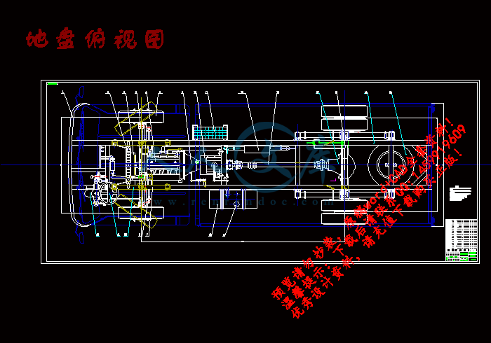
地盘俯视图.dwg

外文原文.doc

底盘总体主视图.dwg

开题报告.doc

拖拉机的分类--中英文翻译.doc

轻型载货汽车底盘设计.doc

轻型载货汽车设计(底盘设计)

摘 要

本次设计的对象是轻型卡车的总体设计,要求该车有良好的动力性和经济性。总体设计的目的是将各分总成协调地组装在一起,避免各总成之间出现干涉现象,从而实现汽车总成的运动准确性及行驶平顺性。驾驶室总成设计要满足客户对舒适性的要求;货厢总成要有足够的尺寸来保证额定装载质量,但也要考虑汽车的最小转弯半径及机动性;底盘总成要避免转向纵拉杆和前悬架钢板弹簧的干涉,保证各总成固定的刚度,使之在行驶中不产生共振。

设计中做了以下工作:总体布置,其中包括汽车主要技术参数的确定,发动机和轮胎的选择等;稳定性的计算,涉及纵向、横向行驶稳定性的计算,最小转向半径的计算等;汽车的动力性计算,包括各挡车速的计算,爬坡度的计算,加速性能的计算,驱动力和行驶阻力的平衡,功率的平衡;汽车燃油经济性的计算。

综合分析、计算、验证得知,本次设计基本满足了设计任务书的要求。

关键字:货车,底盘,总体布置,转向纵拉杆,前悬架,驱动力

THE OVERALL DESIGN OF LIGHT TRUCK

ABSTRACT

This light truck must have adequate hauling power and high working efficiency. The purpose of the overall design is to coordinate the subassemblies got together to avoid interfering between them. And then making the truck’s movement is veracity, and to ensure the ride comfort. The design of the cab must make the driver feel comfortable. The pay cube should be big enough to fulfill the rating carrying ability, but we have to consider the tightest turning radius and flexibility as well. There shouldn’t be interfere among steering drag rod and road spring of front suspension in the chassis. The subassemblies must be fixed to the chassis firmly to prevent syntony in the driving.

Main work is as following in this design: the General arrangement, including selecting the main technology parameters, the engine, the tires and so on; the Calculating of Stability , involving portrait stability and landscape orientation stability while driving, the tightest turning radius; the Power performance calculation, including the calculating of speeds on all gear ratios, gradability, acceleration characteristic, the balance between driving force and running resistance, as well as the power; the Calculation of Fuel Economy.

Through the generalized analysis, computation, confirmation, we confirm that this design has on the whole satisfied the description requirements.

KEY WORDS: Truck, Chassis, General arrangement plan, Steering drag rod, Front suspension, Driving force

第一章前言

从1886年德国人卡尔奔驰和戈特利布载姆勒用四冲程汽油机制成汽车以来,已有一百多年的历史。一百多年来,汽车的发展给人类带来了巨大而深刻的变化。汽车以其惊人的产量、卓越的性能和多种用途渗透到人类活动的各个领域,并以它完美的造型艺术和舒适的内部设施而深受人们的喜爱。汽车已成为各国国民经济和社会生活中不可缺少的运输工具,成为二十世纪改造世界的机器和现代文明的标志。

目前,计算机技术在汽车设计、试验和生产制造中被广泛地应用。现在普遍用计算机进行汽车的总体布置方案设计,确定整车性能并进行动态模拟试验。生产用图已用计算机绘制,且只需几个星期或稍长的时间,就能将设计意图加以实现,并提供多种生产用图纸。对汽车车身全盘实现计算机辅助设计和制造,即所谓的CAD/CAM,大大缩短了计算、绘图时间,提高了设计速度和质量。

参考文献

[1]陈家瑞.汽车构造(上、下册).北京:机械工业出版社,1993

[2]蔡春源.机械零件设计手册(3版)上、下册.北京:冶金工业出版社,1996

[3]王望予.汽车设计(3版).北京:机械工业出版社,1995

[4]余志生.汽车理论(3版).北京:机械工业出版社,1981

[5]黄金陵.汽车车身结构与设计.吉林:吉林工业大学,1985

[6]刘鸿文.材料力学(上、下册).北京:高等教育出版社,1998

[7]张义民 闻邦春.汽车技术.1997,第九期,p7-20

[8]刘惟信.汽车设计.北京:清华大学出版社,2000

[9]王昆  何小柏等.机械设计.北京:高等教育出版社,1995

[10]吉林工业大学汽车教研室.汽车设计,北京:机械工业出版社,1981

[11]张洪欣.汽车设计.北京:机械工业出版社,1989

[12]机械设计手册(第3卷). 北京:机械工业出版社,1991

[13]郭竹亭.汽车车身设计.吉林:吉林科学技术出版社,1994

[14]程正,马芳.汽车造型.吉林:吉林科学技术出版社,1992

[15]温吾凡.汽车人体工程学. 吉林:吉林科学技术出版社,1991

[16](德)阿达姆.汽车行驶性能.北京:科学技术出版社,1992

[17]刘惟信.驱动桥.北京:人民交通出版社,1987

[18]黄天泽、黄金陵.汽车车身结构与设计.北京:机械工业出版社,2003

[19]吴宗泽.机械设计使用手册.北京:化学工业出版社,1999

[20]《汽车百科全书》编纂委员会 编.汽车百科全书(上册).北京:机械工业出版社,1992

[21]魏鑫,张迅,田景崎 编.最新国外汽车车型手册.北京:机械工业出版社,1991


内容简介:
1 Classification of Tractors The tractor is a wheeled or tracked self-propelled vehicle used as a power means for moving agricult ural, road building, and other machines equipped with special tools, and also for towing trailers. The tractor engine can be used as a prime mover for active moving tools or starting farm machinery through the intermediary of the power takeoff shaft or belt pulley. The uses of the tractor in agriculture are many, and so different types of tractors are needed to do different types of farm work. Farm tractors are classified as follows. AS TO PUR POS E, modern farm tractors are classed in three groups: general-purpose tractors (land utility), universal-row-crop (row-crop utility) tractors, and special-purpose tractors. Land utility tracto rs are used for major farm operations common to the cultivation of most crops, such as tillage, digging, general cultivations, harrowing, sowing, and harvesting. The tractors are characterized by a low ground clearance, increased engine power, and good tra ction. Thanking to their wide tires or tracks enabling them to develop a high pull. Universal-row-crop tractors are intended for row-crop work, as well as for many other field tasks. For this purpose, some row-crop utility tractors are provided with replac eable driving wheels of different tread widths-wide for general far m work and narrow for row-drop work, in order not to damage plants, the tractors have a high ground clearance and a wide wheel track that can be adjusted to suit the particular inter-tow distance. Special-purpose tractors are modifications of standard land or row-crop utilit y tractor models and are used for definite jobs, and under nts 2 certain condit ions. Thus, special tractors used to mechanize the cultivation of cotton have a single front whee l, swamp tractors are equipped with w ide tracks enabling them to operate on marshy soils, and hills ide tractors are designed to work on hills ides sloping at up to 16. AS TO THE D ES IGN OF THE R UNNIN G GEAR, tractors are divided into crawler (track- laying) and wheeled types. Crawler tractors are distinguished by a large ground contact area and therefore have a good track adhesion; they crush and compact the soil ins ignificantly. S uch tractors show a high cros s-country power and are capable of developing a high pull. Wheeled tractors are more versatile and can be used for both field and transport work, but their traction is lower than that of crawler tractors. Main Compone nt Parts of tractor The tractor is comp lex self-propelled machine consisting of separate interacting mechanisms and units that can be combined into certain groups. Irrespective of particular design features, all tractors consist of engine, drive line, running fear, steering mechanis m, working attachments, and auxiliary equipments. THE ENGINE converts thermal energy into mechanical energy. THE DR IVE LIN E comprises a set of mechanis ms which transmit the torque developed by the engine to the driving wheels or tracks and change the driving torque bo th in magnitude and direction. The drive line inc ludes the clutch, flexible coupling, transmission (gearbox) and rear axle. The clutch serves to disconnect the engine shaft from the transmission for a short period of time while the driver is shift ing gears nts 3 and also to connect smoothly the flow of power from the engine to the driving wheels or tracks when starting the tractor from rest. The flexib le coupling incorporates elastic elements allow ing to connect the clutch shaft and the transmission drive shaft w ith a slight misalignment. The transmission makes it possible to change the driving torque and the running speed of the tractor by engaging different pairs of gears. With the direction of rotation of the engine shaft remaining the same, the transmission enables the tractor to be put in reveres. The rear- axle mechanisms increase the driving torque and transmit it to the driving wheels or tracks at right angles to the drive shaft. In most tractors, the rear axle also comprises brakes. In the wheeled tractor, as dist inct from its crawler counterpart the drive line inc ludes the differential which enables the driving wheels to revolve with different speeds when making turns of running over a ragged terrain, at which time the left -and right- hand wheels must travel different distances during one and the same time. THE RUNN IN G GEAR is needed for the tractor to move. The rotation of the driving wheels (or the movement of the tracks) in contact with the ground is converted into translatory motion of the tractor. THE S TEERIN G M ECHAN ISM serves to change the direction of movement of the tractor by turning its front wheels (in wheeled tractors) or by varying the speed of one of the tracks (in crawler tractors). THE WORKIN G ATTACHM EN TS of the tractor are used to utilize the useful power of the tractor engine for various farm tasks. They include the power takeoff shaft, drawbar (hitch device), implement-attaching (mounting) system, and belt pulley. THE TR ACTOR AUXILIAR IES inc lude the driver s cab with a spring- mounted seat a nd heating and ventilation equipment, hood, lighting equipment, tell tales (indicators), horns, etc. nts 4 The Clutch The clutch is located in the power train between the engine and the transmission. The clutch allows the driver to couple the engine or to uncouple the engine from the transmiss ion while he is shift ing gears or starting the tractor moving from rest. Modern tractors use fr iction clutches, ones employing fr iction forces to transmit power. The friction sur faces in such clutches are provided by discs, whose number depends on the magnit ude of torque to single- and double- disc clutches. C lutch driving disc (pressure plate) is connected to the engine flywheel, while driven disc is mounted on transmission clutch ( input) shaft. The driven disc has splines in its hub that match splines on the input shaft. The disc is tight ly c lamped between the pressure plate and the flywheel by a series of coil springs, called the pressure springs held between the clutch cover and the pressure plate. O wing to the frict ion forces arising between the fr iction surfaces of the flywheel, driven disc, and pressure plate , torque transmission input shaft. In this position, the clutch is engaged. The clutch is operated by the clutch linkage which passes on the movement of clutch pedal to clutch release (throw-out) bearing. When the driver steps on the pedal, the clutch linkage, which includes an operating rod and a release fork, forces the release bearing inward (to the left). As the release bearing moves left, it pushes against the inner ends of three release levers. When the inner ends of three release levers are pushed in by the release bearing, the outer ends of the levers move the pressure plate to the right, compressing pressure springs. With the spring pressure off the driven d isc, spaces appear between the disc, the flywheel, and the pressure plate. Now the clutch is disengaged (released), and the flywheel can rotate without sending power through the driven disc. When the clutch pedal is released, the pressure springs nts 5 force the pressure plate to the left. The driven disc is again clamped tight ly between the flyw heel and the pressure plate. The driven disc must again rotate with the flywheel. In this position, the clutch is engaged. The init ial s lipping of the driven disc, which occurs unt il the disc is fully cla mped between the flywheel and the pressure plate, tends to make the engagement smooth. The clutch described above is known as the spring- loaded dry friction type. Propelle r Shaft and Universal Joint The propeller shaft is a drive shaft to carry the power from the transmission to the rear- wheel axels. It connects the transmission ma in, or output shaft to the differential at the rear axels. Rotary motion of the transmission main shaft is carried by the propeller shaft to the differential, causing the rear wheels to rotate. The propeller-shaft design must take two facts into consideration. F irst, the engine and transmission are more or less rigidly attached to the car frame. S econd, the rear-axle housing (with wheels and differentia l) is attached to the frame by springs. As the rear wheels encounter irregularit ies in the road, the springs are compressed or expanded. These change the angle of drive and the distance between the transmission and the differentia l, and the propeller shaft should take care of these two changes. That is to say, as the rear axle housing, with differentia l and wheels, moves up and down, the angle between the transmission output shaft and propeller shaft changes. The reason why the angle increases is that the rear axle and differential move in a shorter than the propeller shaft. The center pointer of the axle- housing is rear-spring or control-arm attachment to the frame. In order that the propeller shaft may take care of these two changes, it must incorpora te two universal joints to permit variations in the angle of drive. There must be a set of slip joint to make the propeller shaft change. nts 6 The propeller shaft may be solid or hollow, protected by an outer tube or exposed. Some applications inc lude bearings at or near the center of the propellers which are supported by a center bearing and coupled together by universal joints. A universal joint is essentially a double- hinged joint consisting of two y-shaped yokes, one on the driving shaft and the other on the driven shaft, and across-shaped me mber called the spider. The four arms of the spider, known as trunnions, are assembled into bearings in the ends of the two shaft yokes. The driving shaft causes the spider to rotate, and the other two trunnions of the sp ider cause the driven shaft to rotate. When the two shafts are at an angle to each other, the b earings in the yokes permit the yokes to swing around on the trunnions with each revolut ion. A variety of universal joints have been used on automobiles, but the types now in most common use are the ball-and-trunnion joints. A slip joint consists of outside splines on one shaft and matching internal splines in the mating hollow shaft. The splines cause the two shafts to rotate together but permit the two to move endwise with each other. This accommodates any effective change of length of the propeller shaft as the rear axles move toward or away from the car frame. nts 河南科技大学毕业设计(论文)开题报告 (学生填表) 院系:车辆与动力工程学院 2013 年 4 月 12 日 课题名称 轻型载货汽车设计(底盘设计) 学生姓名 葛帅 专业班级 车辆 092 课题类型 毕业 设计 指导教师 薛运起 曹艳玲 职称 高工 副教授 课题来源 组合 生产 1. 设计(或研究)的依据与意义 随着现在科学技术的发展,人们出行的日益繁忙,汽车作为一种快速便捷的交通工具,在外出,旅行,载货中起着越来越重要的作用,给人们生活带来了许多 的方便。被称为“改变世界的工具”。汽车品种的多样性可满足各种生产、生活活动的需求,而且有良好的社会效益。 汽车的进步如同社会进步一样,与我们息息相关。从早期的蒸汽机到后来的内燃机车再到现在的电动汽车、燃料汽车等,反映出了一条汽车发展的轨迹。汽车诞生 100 多年来,涌现了各种有关汽车技术发明,汽车面貌日新月异,随着汽车工业的不断发展,人们对汽车各方面的性能也提出更高的要求。不仅要求汽车有良好的动力性,经济性,更要求有最好的安全性,更低的污染以及舒适的乘坐性能和轻便的驾驶性能等。 底盘是 汽车 上由传动系 、行驶系、转向系和制动系四部分组成的组合,支承、安装汽车发动机及其各部件、总成,形成汽车的整体造型,承受发动机动力,保证正常行驶。 底盘由传动系、行驶系、转向系和制动系四部分组成。 nts 2. 国内外同类设计(或同类研究)的概况综述 国内轻型卡车产品与国外产品相对,对国内环境适应能力更强。我国轻型车使用范围广阔,从田间到工地,从广大农村到大城市,各种环境对轻型卡车的环境适应能力提出了较高的要求。我国轻型卡车制造商,对产品多年持续不断的适应性设计,使我国轻卡产品能够应对国内复杂的使用环境,而国外进口同类产品 ,对国内的环境适应能力则相对薄弱很多。 随着世界汽车对汽车发动机动力性、 经济 性和排放提出了更高要求和 计算 机技术的迅速 发展 ,柴油机被公认为节能的代表和减少汽车尾气排放污染的有力工具,汽车柴油化也是汽车发动机发展的一大趋势。柴油机的开发焦点已由传统的 优先考虑经济性、可靠性和耐久性逐步转为目前的优先考虑环保的要求,即以优先保护好人类赖以生存的地球环境为出发点去考虑采用何种技术,去评价其先进性。 近几年来国内轻卡在设计上已经趋于成熟,但由于 大众思维观念制约,在安全性和耐久性方面与国外产品还有一定差距。日前我国轻卡市场竞争日趋激烈,主要是在功能和舒适性上比拼,在发动机功率、驾驶室宽度、外观造型、舒适化程度等方面进展迅速,而可靠性方面,受车辆制造成本限制,提高速度并不快。此外,国内轻型卡车在环保性方面落后于总体水平。由于国内轻型卡车以中低端产品为主,提升环保标准增加的成本,会降影响用户接受能力,因此在环保方面,轻型卡车产品一直处于被动接受状态,在环保控制零部件选择上,使用不达标准产品,降低环保功能件成本,结果导致轻型货车的发展与国外产品存在一定的 差距,因此,柴油货车的环保性能设计具有很大的市场前景。 燃料性能的改进,对减少排放起到很大作用,日本继美欧之后,从 1997 年开始把轻油中的硫含量降到 0.05%以下,以此大幅度减少排放颗粒中的硫酸盐,同时减少 EGR 造成的发动机内部的腐蚀磨耗及催化剂中毒;进一步减少硫含量,提高十六烷值,可进一步降低 NOx。减少芳香烃,尤其是减少 3 环以上的芳香族成分,可减少排放颗粒中的硫化物、降低 90%的蒸馏温度、改进点火性能;通过使用含氧燃料或添加剂,可降低黑烟颗粒。为了适应低硫化及喷射压力的大大增加,确保燃油喷射装置的润滑性, 人们对燃料的改进开发寄予了很大期望。 nts 3. 课题设计(或研究)的内容 完成轻型汽车的底盘设计,进行发动机与传动系的合理匹配优化计算,确定最佳的变速器与驱动桥的主要参数。总工作量不少于 3 张零号图纸,编写设计说明书,内容不少于 12000 字,说明书要求计算机打印 。 至少完成 1 张 1 号图纸的机绘图,保证 30 学时的计算机上机工作量。阅读不少于 15 篇的参考文献;编写不少于 400字符的中文摘要,并翻译成外文;要有 1 万字符的外文翻译资料。 4. 设计(或研究)方法 根据所给技术条件和要求,并参照其他类似的成熟车型对比设计。 由经验公式确定一系列的参数,包括总体的外型尺寸,轴间距,载荷分布等。还有制动器的所需的制动力,力矩等。并根据要求进行校核。 5. 进度计划 调研,收集资料 一周 确定方案,画草图 四周 完成总装图 四周 撰写说明书,整理图纸 二周 互评、答辩 一周 指导教师意见 指导教师签字: 年 月 日 研究所(教研室)意见 研究所所长(教研室主任)签字: 年 月 日 nts 1 拖拉机的分类 拖拉机是一种轮式或履带式的自走式车辆工具,它能被用来做移植农作物,铺路和其他装备特殊工具的机械的动力装置。也能用做牵引挂车的动力,拖拉机的发动机也能被用来做自动工具,固定式农业机械的有原动力,通过用力输出轴和皮带轮做中间媒介。 拖拉机在农业中的应用是非常的广泛的,并且不同类型的拖拉机做不同的农业作业。 农业拖拉机被分为以下几类。 就功能来说,现代的农用拖拉机可以分为三类,普通功能的拖拉机,中耕拖拉机和专用拖拉机。 普通用途的拖拉机主要的农业作业是大部分农作物的栽培,比如耕地,犁地,耕种,耙地, 播种和收割。 这种拖拉机的典型 特征就是有一个比较小的离地间隙,增加了发动机的扭矩和有比较好的牵引力,由于它们有较宽的轮胎或履带,使他们能够产生比较大的牵引力。 中耕拖拉机主要用来中耕作业,也可以进行许多其它的田间作业,为了达到这个目的,一些中耕拖拉机被装备了不同胎面宽度的可替换的驱动轮。用来进行一般的田间作业和耙地,为了不损坏农作物,这种拖拉机有一个比较大的离地间隙和比较宽的轮胎,能适应特殊的农作物间距。 专用拖拉机不同 于 普 通的拖拉机和中 耕式拖拉机, 它被用于特定的作业,或者在特定的条件下用于不同的作业。因此被 用来 棉花中耕机械化的专用拖拉机常常有一个前轮,在沼泽地里工作的拖拉机一般装备有很宽的履带,这样能够使它们在潮湿的土壤上工作。山地拖拉机一般被设计能在 16 度 的斜坡上工作。 按驱动装置的设计,拖拉机有可分为轮式和履带式。 履带式拖拉机因它较大的接地面积而著称,所以它有一个很好的牵引附着性,它们能碾压土壤并能紧紧的抓住土壤。因此这种拖nts 2 拉机有很好的越野性并且能够提供很好的牵引力。 轮式拖拉机的应用也很广泛,能被用来在田间作业并且能够用来进行交通运输,但是它们的牵引能力比履带式拖拉机要小。 拖拉机的主要组成部分 拖拉 机是复杂的自走 式机械,它由相 互独立相互作 用的机构和单元组合而成。 如果不考虑特殊的设计,所有的拖拉机都有发动机,传动系,行驶系,转向系,作业机构和辅助装置组成。 发动机把燃料的化学能转化成机械能。 传动系包括一系列的机械装置,它们能传递发动机产生的扭矩给驱动轮或履带。并且能把驱动扭矩变成有大小和方向的力,传动系包括,离合器,连轴器,变速器和后桥。 离合器的主要用途就是当驾驶员正在挂挡时,暂时的把发动机输出轴与变速器分离一段时间。当发动机从停机启动时,它也能使发动机传递到驱动轮上的较低的动力连接平衡。 连轴器 包括很多的弹 性元件,这些弹 性元件能够把 不在同一条直线上的离合器轴和变速器轴连接在一起。 变速器通过不同的啮合齿轮,使改变驱动扭矩和发动机转速成为可能。在发动机曲轴旋转方向不变的情况下,变速器能够是拖拉机倒驶。 后桥机构增加了驱动扭矩,且把它传递到驱动轮上或履带上在适当的角度传给驱动轴。在大部分的拖拉机上,后桥上也包含刹车。 在轮式拖拉机上,不同于履带式的地方。就是传动系还包括差速器,当拖拉机在转弯时或行驶在不平整的路面上时,它能是驱动轮以不同的速度旋转,它的左右轮在相同的时间内行驶过不同的距离。 行驶系能够 使拖拉机 移动,驱动轮或 者履带和地面 接触的旋转运动被转化成拖拉机的直线运动。 转向系主要用来改变拖拉机的行驶方向,在轮式拖拉机上是靠nts 3 旋转它的前轮,在履带式拖拉机上,是靠改变一个履带的速度。 作业机构被用来耕作。充分应用拖拉机发动机的动力去实现各种农作业。它包括动力输出轴,悬挂机构,农具挂接机构,皮带轮。 辅助装置包括装有弹簧坐椅及加热、通风装置的驾驶室,发动机罩,照明设备,指示器,喇叭等。 离合器 在传动系中离合器位于发动机与变速器之间,作用就是使驾驶员可以把发动机与变速器结合和脱离。 现代拖拉机上广泛应用摩 擦片式离合 器。这种离合 器利用摩擦力来传递动力,这种离合器的摩擦面由压盘提供,它的数量取决于传递扭矩的大小。大部分拖拉机上广泛应用的是单片和双片式离合器。 单片离合器的压盘和发动机飞轮连接在一起,但是从动盘安装在变速器离合器输入轴上。从动盘上有花键毂与输入轴上的花键相配合。从动盘被一组螺旋弹簧紧紧地压在压盘与飞轮之间,这一组压力弹簧被支撑在离合器和压盘之间,由于在飞轮,从动盘与压盘之间产生了摩擦力,所以扭矩能够被从发动机传递到变速器输入轴,在这个位置时离合器开始工作。 离合器通过离合器转向传动机构来操作,离合 器转 向传动机构包括一个操作杆和一个分离拨叉。它能够传递离合器踏板的运动给离合器分离轴承。当驾驶员踏离合器踏板时,离合器转向传动机构迫使分离轴承向内(向左)移动。随着分离轴承向左移动,它就向左推三个分离杆的内端。当三个分离杆的内端被分离轴承向左推时,分离杆的外端就使压盘向右移动,压缩螺旋弹簧。随着弹簧压力从从动盘上消失,在从动盘,飞轮和压盘之间出现空隙,这时离合器被分离。但飞轮继续转动,但不通过从动盘传递动力。当离合器踏板被松开,螺旋弹簧通过使压盘向左移动,从动盘再次被紧紧的压在飞轮与压盘之间,从动盘再次随着 飞轮一 起旋转。在这个位 置,离合器开始工作,刚开始从动盘进行滑动,直到它被完全压紧在飞nts 4 轮与从动盘之间,使工作趋于平滑。上边所描述的是干式摩擦弹簧离合器。 传动轴和万向节 传动轴将动力从变速器传送到后桥的驱动轴上。传动轴将变速器的主轴或是输出轴,连接到后桥上的差速器。变速器主轴的旋转运动通过传动轴传递到差速器上,使后车轮转动。 设计传动轴时必须考虑两个因素。第一,发动机和变速器是刚性地安装在车架上。第二,后桥壳(连同车轮和差速器)是通过弹性元件与车架相连。当后车轮在高低不平的路面上滚动时,弹簧上下伸缩,使变速器 和差速 器之间的传动角度 和距离发生变化。 传动轴要能适应这些变化,也就是说,当后桥壳随差速器车轮一起上下运动时,与变速器输出轴之间的角度变大的原因是后桥和差速器运动的弧度小于传动轴运动的弧度。后桥壳弧线摆动的中心点是固定在车架的后弹簧或控制臂上。为了使传动轴适应这两种变化,就笔削装有两套独立的装置。一个或几个万向节来适应传动角度的变化,一套伸缩花键,能够改变传动轴的现有长度。 传动轴可以是实心的也可以是空心的,有套管加以保护或裸露在外。有些传动轴在中心或在中心附近装有支撑轴承。两段传动轴之间各有中间支撑轴承,并 由万向节传动连接。 万向节基本是个双铰链节,有两个 Y 型万向叉,一个在主动轴上,另一个在从动轴上,还有一个叫万向节十字轴的十字形零件。万向节十字轴的四个轴颈叫做万向节十字头,分别装在两个万向节叉顶端的轴承中。主动轴使万向节十字轴转动,另外两个万向节十字头使从动轴转动。当两轴相互处在同一角度上,主动轴转动时万向叉上的轴承使万向节叉绕万向节十字轴摆动。汽车上使用的万向节有多种形式,但是使用最普遍的是双十字轴万向节、等速万向节和球叉万向节。 伸缩花键由在传动轴上的外花键和与之相连的空心轴中对应的内花键组成。伸缩花键 使 两轴一起转动,也 能使两轴相对移动 。当nts 5 后桥在车架上向前或向上运动时,这种结构足以调整转动轴长度的任何变化。 Classification of Tractors The tractor is a wheeled or tracked self-propelled vehicle used as a power means for moving agricult ural, road building, and other machines equipped with special tools, and also for towing trailers. The tractor engine can be used as a prime mover for active moving tools or starting farm machinery through the intermediary of the power takeoff shaft or belt pulley. The uses of the tractor in agriculture are many, and so different types of tractors are needed to do different types of farm work. Farm tractors are classified as follows. AS TO PUR POS E, modern farm tractors are classed in three groups: general-purpose tractors (land utility), universal-row-crop (row-crop utility) tractors, and special-purpose tractors. Land utility tractors are used for major farm operations common to the cultivation of most crops, such as tillage, digging, general cultivations, harrowing, sowing, and harvesting. The tractors are characterized by a low ground clearance, increased engine power, and good traction. Thanking to their wide tires or tracks enabling them to develop a high pull. Universal-row-crop tractors are intended for row-crop work, as well as for many other field tasks. For this purpose, some row-crop utility tractors are provided with replaceable driving wheels of different tread widths-wide for general far m work and narrow for row-drop work, in order not to damage plants, the tractors have a high ground clearance and a wide wheel track that can be adjusted to suit the particular inter-tow distance. nts 6 Special-purpose tractors are modifications of standard land or row-crop utilit y tractor models and are used for definite jobs, and under certain condit ions. Thus, special tractors used to mechan ize the cultivation of cotton have a single front wheel, swamp tractors are equipped with w ide tracks enabling them to operate on marshy soils, and hills ide tractors are designed to work on hills ides sloping at up to 16. AS TO THE D ES IGN OF THE R UNNIN G GEAR, tractors are divided into crawler (track- laying) and wheeled types. Crawler tractors are distinguished by a large ground contact area and therefore have a good track adhesion; they crush and compact the soil ins ignificantly. S uch tractors show a high cros s-country power and are capable of developing a high pull. Wheeled tractors are more versatile and can be used for both field and transport work, but their traction is lower than that of crawler tractors. Main Compone nt Parts of tractor The tractor is comp lex self-propelled machine consisting of separate interacting mechanisms and units that can be combined into certain groups. Irrespective of particular design features, all tractors consist of engine, drive line, running fear, steering mechanis m, working attachments, and auxiliary equipments. THE ENGINE converts thermal energy into mechanical energy. THE DR IVE LIN E comprises a set of mechanis ms which transmit the torque developed by the engine to the driving wheels or tracks and change the driving torque bo th in magnitude and direction. The drive line inc ludes the clutch, flexible coupling, transmission (gearbox) and rear axle. nts 7 The clutch serves to disconnect the engine shaft from the transmission for a short period of time while the driver is shift ing gears and also to connect smoothly the flow of power from the engine to the driving wheels or tracks when starting the tractor from rest. The flexib le coupling incorporates elastic elements allow ing to connect the clutch shaft and the transmission drive shaft w ith a slight misalignment. The transmission makes it possible to change the driving torque and the running speed of the tractor by engaging different pairs of gears. With the direction of rotation of the engine shaft remaining the same, the transmission enables the tractor to be put in reveres. The rear- axle mechanisms increase the driving torque and transmit it to the driving wheels or tracks at right angles to the drive shaft. In most tractors, the rear axle also comprises brakes. In the wheeled tractor, as dist inct from its crawler counterpart the drive line inc ludes the differential which enables the driving wheels to revolve with different speeds when making turns of running over a ragged terrain, at which time the left -and right- hand wheels must travel different distances during one and the same time. THE RUNN IN G GEAR is needed for the tractor to move. The rotation of the driving wheels (or the movement of the tracks) in contact with the ground is converted into translatory motion of the tractor. THE S TEERIN G M ECHAN ISM serves to change the direction of movement of the tractor by turning its front wheels (in wheeled tractors) or by varying the speed of one of the tracks (in crawler tractors). THE WORKIN G ATTACHM EN TS of the tractor are used to utilize the useful power of the tractor engine for various farm tasks. They include the power takeoff shaft, drawbar (hitch device), implement-attaching (mounting) system, and belt pulley. THE TR ACTOR AUXILIAR IES inc lude the driver s cab with a nts 8 spring- mounted seat a nd heating and ventilation equipment, hood, lighting equipment, tell tales (indicators), horns, etc. The Clutch The clutch is located in the power train between the engine and the transmission. The clutch allows the driver to couple the engine or to uncouple the engine from the transmiss ion while he is shift ing gears or starting the tractor moving from rest. Modern tractors use fr iction clutches, ones employing fr iction forces to transmit power. The friction sur faces in such clutches are provided by discs, whose number depends on the magnit ude of torque to single- and double- disc clutches. C lutch driving disc (pressure plate) is connected to the engine flywheel, while driven disc is mounted on transmission clutch ( input) shaft. The driven disc has splines in its hub that match splines on the input shaft. The disc is tight ly c lamped between the pressure plate and the flywheel by a series of coil springs, called the pressure springs held between the clutch cover and the pressure plate. O wing to the frict ion forces arising between the fr iction surfaces of the flywheel, driven disc, and pressure plate , torque transmission input shaft. In this position, the clutch is engaged. The clutch is operated by the clutch linkage which passes on the movement of clutch pedal to clutch release (throw-out) bearing. When the driver steps on the pedal, the clutch linkage, which includes an operating rod and a release fork, forces the release bearing inward (to the left). As the release bearing moves left, it pushes against the inner ends of three release levers. When the inner ends of three release levers are pushed in by the release bearing, the outer ends of the levers move the pressure plate to the right, compressing pressure springs. With the spring pressure off the driven d isc, spaces appear between the disc, the nts 9 flywheel, and the pressure plate. Now the clutch is disengaged (released), and the flywheel can rotate without sending power through the driven disc. When the clutch pedal is released, the pressure springs force the pressure plate to the left. The driven disc is again clamped tight ly between the flyw heel and the pressure plate. The driven disc must again rotate with the flywheel. In this position, the clutch is engaged. The init ial s lipping of the driven disc, which occurs unt il the disc is fully cla mped between the flywheel and the pressure plate, tends to make the engagement smooth. The clutch described above is known as the spring- loaded dry friction type. Propelle r Shaft and Universal Joint The propeller shaft is a drive shaft to carry the power from the transmission to the rear- wheel axels. It connects the transmission ma in, or output shaft to the differential at the
温馨提示:
1: 本站所有资源如无特殊说明,都需要本地电脑安装OFFICE2007和PDF阅读器。图纸软件为CAD,CAXA,PROE,UG,SolidWorks等.压缩文件请下载最新的WinRAR软件解压。
2: 本站的文档不包含任何第三方提供的附件图纸等,如果需要附件,请联系上传者。文件的所有权益归上传用户所有。
3.本站RAR压缩包中若带图纸,网页内容里面会有图纸预览,若没有图纸预览就没有图纸。
4. 未经权益所有人同意不得将文件中的内容挪作商业或盈利用途。
5. 人人文库网仅提供信息存储空间,仅对用户上传内容的表现方式做保护处理,对用户上传分享的文档内容本身不做任何修改或编辑,并不能对任何下载内容负责。
6. 下载文件中如有侵权或不适当内容,请与我们联系,我们立即纠正。
7. 本站不保证下载资源的准确性、安全性和完整性, 同时也不承担用户因使用这些下载资源对自己和他人造成任何形式的伤害或损失。
提示  人人文库网所有资源均是用户自行上传分享,仅供网友学习交流,未经上传用户书面授权,请勿作他用。
关于本文
本文标题:轻型载货汽车底盘设计【优秀汽车底盘全套课程毕业设计含2张CAD图纸】
链接地址:https://www.renrendoc.com/p-474794.html

官方联系方式

2:不支持迅雷下载,请使用浏览器下载   
3:不支持QQ浏览器下载,请用其他浏览器   
4:下载后的文档和图纸-无水印   
5:文档经过压缩,下载后原文更清晰   
关于我们 - 网站声明 - 网站地图 - 资源地图 - 友情链接 - 网站客服 - 联系我们

网站客服QQ:2881952447     

copyright@ 2020-2025  renrendoc.com 人人文库版权所有   联系电话:400-852-1180

备案号:蜀ICP备2022000484号-2       经营许可证: 川B2-20220663       公网安备川公网安备: 51019002004831号

本站为文档C2C交易模式,即用户上传的文档直接被用户下载,本站只是中间服务平台,本站所有文档下载所得的收益归上传人(含作者)所有。人人文库网仅提供信息存储空间,仅对用户上传内容的表现方式做保护处理,对上载内容本身不做任何修改或编辑。若文档所含内容侵犯了您的版权或隐私,请立即通知人人文库网,我们立即给予删除!