翻译.doc

直三通注塑模设计【优秀含16张CAD图纸+塑料模具全套毕业设计】【侧抽】

收藏

资源目录
跳过导航链接。
直三通注塑模设计【优秀含16张CAD图纸+塑料模具全套毕业设计】【侧抽】.zip
翻译.doc---(点击预览)
直三通注塑模设计说明书.doc---(点击预览)
开题报告.doc---(点击预览)
任务书.doc---(点击预览)
侧型芯.dwg
侧滑块.dwg
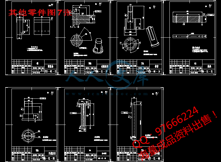
其他零件图7张.dwg
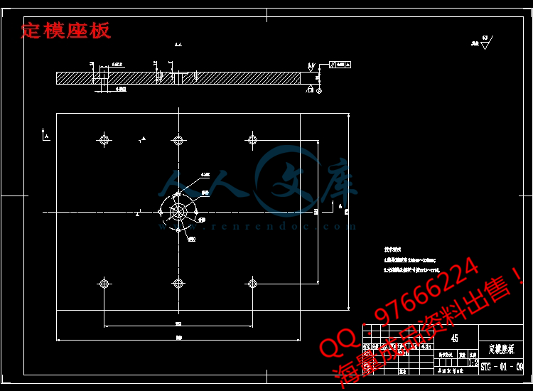
动模座板.dwg
动模板.dwg
塑件图.dwg
定模座板.dwg
定模板.dwg
推管固定板.dwg
支撑板.dwg
装配图.dwg
压缩包内文档预览:
预览图 预览图 预览图 预览图 预览图 预览图 预览图 预览图 预览图 预览图 预览图 预览图 预览图
编号:479274    类型:共享资源    大小:2.86MB    格式:ZIP    上传时间:2015-10-07 上传人:小*** IP属地:福建
45
积分
关 键 词:
三通 注塑 设计 优秀 优良 16 cad 图纸 塑料模具 全套 毕业设计 侧抽
资源描述:

!【详情如下】【注塑塑料模具课题】CAD图纸+word设计说明书.doc[25000字,59页]【需要咨询购买全套设计请加QQ97666224】.bat

侧型芯.dwg

侧滑块.dwg

其他零件图7张.dwg

动模座板.dwg

动模板.dwg

塑件图.dwg

定模座板.dwg

定模板.dwg

推管固定板.dwg

支撑板.dwg

装配图.dwg

任务书.doc

开题报告.doc

设计说明书.doc[25000字,59页]

翻译.doc

摘  要


三通管作为一种连接件在日常生活中应用广泛,本文对塑料模具的设计方法及过程进行了阐述。包括了塑件结构的分析和材料的选择,拟定模具结构形式、注塑机型号的选择,浇注系统的形式和浇口的设计、成型零件的设计、模架的确定和标准件的选用。合模导向机构的确定、脱模推出机构的确定,侧向分型与抽芯机构的设计、排气系统的设计、模具温度调节系统的设计、典型零件制造工艺、模具材料的选用等。


关键词  三通管;注塑模;导向;分型;脱模


ABSTRACT

The Three Links Pipeline as a kind of attachment is widely used in daily life. In the paper, the design method and processes of the plastics mould have been described. including the structural analysis and material selection of the plastic, drawing up the mold structural style, selection of the injection molding machine, the form of feed system and the design of the runner, the design of shaped parts, mold-determination and selection of standards, the oriented institutions to identify for mold clamping, the determination of ejector organization for de-molding, the design of lateral core-pulling organization, the design of the mold pumping system, the design of the system for controlling the mold temperature, the manufacturing processes of typical components, selection of the mold material and so on.

Keywords  Three links pipeline; Injection mould; director; joint face; stripping


目 录

1  前言…………………………………………………………………………………………1

  1.1  我国塑料模具工业的发展现状……………………………………………………1

  1.2  国际塑料模具工业的发展现状…………………………………………………1                      

        1.2.1  网络的CAD/CAE/CAM一体化系统结构初见端倪………………………2

        1.2.2  AM软件日益深人人心并发挥越来越重要的作用………………………2

        1.2.3  AM软件的智能化程度正在逐渐提高……………………………………2

        1.2.4  设计与3D分析的重要性更加明确………………………………………2

  1.3  我国塑料模具工业和技术今后的主要发展方向…………………………………3

  1.4  本次设计的目的……………………………………………………………………4

2  塑件成型工艺性分析………………………………………………………………………5

  2.1  塑件(直三通)分析………………………………………………………………5

       2.1.1  塑件图(因使用需要对原式样有所改进…………………………………5

       2.1.2  塑件分析…………………………………………………………………5

       2.1.3  成型工艺分析如下………………………………………………………5

  2.2  ABS的注射成型过程及工艺参数…………………………………………………6

       2.2.1  注射成型过程……………………………………………………………6

       2.2.2  ABS的注射工艺参数……………………………………………………6

       2.2.3  ABS化学和物理特性………………………………………………………7

       2.2.4  ABS塑料的主要技术指标…………………………………………………8

3  拟定模具结构形式………………………………………………………………………9

  3.1  分型面的选择………………………………………………………………………9

       3.1.1  分型面的选择原则…………………………………………………………9

       3.1.2  分型面的确定………………………………………………………………9

  3.2  型腔数目的确定……………………………………………………………………10

4  注塑机型号的确定………………………………………………………………………11

  4.1  所需注射量的计算………………………………………………………………11

  4.2  塑件和流道凝料在分型面上的投影面积及所需锁模力的计算………………11

  4.3  选择注射机………………………………………………………………………12

  4.4  注射机有关参数的校核…………………………………………………………13

        4.4.1  型腔数量的校核…………………………………………………………13

        4.4.2  注射机工艺参数的校核…………………………………………………13

        4.4.3  安装尺寸………………………………………………………………14

        4.4.4  开模行程的校核…………………………………………………………14

        4.4.5  模架尺寸与注射机拉杆内间距校核……………………………………14

5  浇注系统的形式和浇口的设计…………………………………………………………15

  5.1  主流道的设计……………………………………………………………………15

        5.1.1  主流道设计要点…………………………………………………………15

        5.1.2  主流道尺寸………………………………………………………………15

        5.1.3  主流道衬套的形式………………………………………………………16

        5.1.4  主流道衬套的固定………………………………………………………17

  5.2  冷料穴的设计……………………………………………………………………17

  5.3  分流道的设计……………………………………………………………………19

        5.3.1  分流道的布置形式………………………………………………………19

        5.3.2  分流道的长度……………………………………………………………19

        5.3.3  分流道的形状及尺寸……………………………………………………19

        5.3.4  分流道的表面粗糙度……………………………………………………20

   5.4  浇口的设计………………………………………………………………………20

        5.4.1  浇口的形式………………………………………………………………21

        5.4.2  浇口类型的选择…………………………………………………………21

        5.4.3  浇口位置的选择…………………………………………………………22

        5.4.4  浇口的尺寸的确定………………………………………………………22

   5.5  浇注系统的平衡…………………………………………………………………22

   5.6  浇注系统凝料体积计算…………………………………………………………22

   5.7  浇注系统各截面流过熔体的体积计算…………………………………………23

   5.8  普通浇注系统截面尺寸的计算与校核…………………………………………23

         5.8.1  确定适当的剪切速率…………………………………………………23

         5.8.2  确定主流道体积流率…………………………………………………23

         5.8.3  注射时间(充模时间)的计算…………………………………………24

         5.8.4  校核各处剪切速率……………………………………………………24

6  成型零件的结构设计和计算……………………………………………………………26

   6.1  成型零件的结构设计……………………………………………………………26

   6.2  成型零件工作尺寸的计算………………………………………………………26

   6.3  型腔零件强度、刚度的校核………………………………………………………30

         6.3.1  根据侧壁厚度校核强度、刚度…………………………………………30

         6.3.2  根据底板厚度校核强度、刚度…………………………………………31

7  模架的确定和标准件的选用……………………………………………………………33

8  合模导向机构的设计……………………………………………………………………35

   8.1  导向结构的总体设计……………………………………………………………35

   8.2  导柱设计…………………………………………………………………………35

   8.3  导套设计…………………………………………………………………………36

9  脱模推出机构的设计……………………………………………………………………37

   9.1  脱模力的计算……………………………………………………………………37

   9.2  脱模机构的结构设计……………………………………………………………38

10  侧向抽芯机构的设计……………………………………………………………………39

   10.1  抽芯距与抽芯力的计算…………………………………………………………39

   10.2  斜导柱截面尺寸的确定…………………………………………………………40

   10.3  楔紧块的设计……………………………………………………………………41

11  排气系统的设计…………………………………………………………………………43

12  温度调节系统设计………………………………………………………………………44

   12.1  冷却时间的计算…………………………………………………………………44

   12.2  冷却管道传热面积及管道数目的简易计算……………………………………45

13  典型零件的制造加工工艺………………………………………………………………48

   13.1  带头导柱的制造工艺……………………………………………………………48

   13.2  编程零件及刀具选择……………………………………………………………49            

   13.3  切削用量确定……………………………………………………………………49

   13.4  编制加工程序……………………………………………………………………49

14  设计小结…………………………………………………………………………………51

参考文献………………………………………………………………………………………52

致谢词…………………………………………………………………………………………53

附录…………………………………………………………………………………………54


内容简介:
注射模具设计和 新型注射成型技术 塑料注射模具是现在所有塑料模具中使用最广的模具,能够成型复杂的高精度的塑料制品。 下面 只是粗略介绍一下。 设计塑料注射模具首先要对塑料有一定的了解,塑料的主要成分是聚合物。如我们常说的 ABS 塑料便是丙烯腈、丁二烯、苯乙烯三种单体采用乳液、本体或悬浮聚合法生产,使其具有三种单体的优越性能和可模塑性,在一定的温度和压力下注射到模具型腔,产生流动变形,获得型腔形状,保压冷却后顶出成塑料产品。聚合物的分子一般呈链状结构,线型分子链和支链型分子认为是热塑性塑料,可反复加热冷 却加工,而经过加热多个分子发生交联反应,连结成网状的体型分子结构的塑料通常是一此次性的,不能重复注射加工,也就是所说的热固性塑料。 既然是链状结构,那塑料的在加工时收缩的方向也是跟聚合物的分子链在应力作用下取向性及冷却收缩有关,在流动方向上的收缩要比其垂直方向上的收缩多。产品收缩也同制品的形状、浇口、热胀冷缩、温度、保压时间及内应力等因素有关。通常书上提供的收缩率范围较广,在实际应用中所考虑的是产品的壁厚、结构及确定注塑时温度压力的大小和取向性。 一般产品如果没有芯子支撑,收缩相应要大些。 塑料注塑 模具基本分为静模和动模。 注射模:注射模主要是用来生产热塑性的零件,尽管有些工艺已经发展为可以用注射模来生产热固性材料的零件。在从一个熔化的熔料箱中把熔料注入型腔中,是相当难解决在这种情况下热固性塑料在几分钟内凝固的问题。注射模的工作原理跟锻造模十分相似。当柱塞向后拉时,塑料粉末被载入加料斗,还有一定数量的塑料进入了加热腔。塑料粉末在加热腔中受到热力和压力的作用下熔化。加热的温度范围在 265 500 华氏度之间。压力在 12000 30000PMa 之间作用下,柱塞向前移动,把熔化的塑料注入模具的型腔中。由于模具 被流通的冷水冷却,塑料凝固成型,当柱塞向后拉出和开模,塑件脱模。注射机可以设计为人工、斗自动、全自动操作。以每分钟注射四次的速率,典型注射机生产的塑件可重达22 盎司,某些注射机可达到每分钟注射六次。除了表面电镀外, 这类模具的用途与铸造模相似。注射模的优点是: 1、 高速注射模适用于大批量生产是可能的 ; 2、 热塑性材料的广泛选择产生了各种有用的特性。 3、 螺纹模具,飞边,侧孔大的薄壁结构的应用成为可能。 成型理论 :板料冲压成形成功机率着冲压件形状的复杂程度减少而增加 ,冲压成形的目的是生产具有一定尺寸 ,形状并 有稳定一致应力状态 ,甚至无起皱无nts裂纹的冲压件 . 冲压有一种至多种成形方式用来成型所需形状 ,它们是弯曲 ,局部成形 ,拉深 ,局部成形用来成形 ,凹陷形状或凸包 ,拉深用来成形 ,啤酒罐之类的冲压件 ,随着冲压件的形状越来越复杂 ,多种成形方法将会被用到同一零件的成型中 ,事实上 ,有很多冲压件上同时有弯曲 ,局部成型 ,拉深模具成型的特征 ,通常有三种形式的模具 ,它们是自由成型 ,局部成形以及拉深形式 . 自由成形 自由成形是用的最基本的一种成形材料的成形模具 ,这类模具只是简单地通过一个冲头在压力机下行过程中把材料“撞击”进入凹模中成形 材料。得到的是由无控制材料流动导致的应罚状态的冲压件,由无约束材料流动产生的“松弛金属区”的出现,冲压件尺寸和形状上趋于不稳定。 局部成形 成形工序中用一压边圈来控制材料流动压边圈是置于模具上的一个多压装置,由带压边圈模具成形的冲压件可分为三部分,它们分别是产品表面,压边圈以及连接这两部分的壁,在凸模一端壁与壁之间的角称作凸模过渡区。 凸模模穴理论上是在壁与压边圈面的交叉处,凸模被置于凸模穴之中,而压边圈被放在凸模穴外凸模的周围,这种模具还有上面的装置将压边圈与凸模联接起来,片料或工序件放到指定位置后压力机 下行,上模开始接触片料,压边圈在凸模周围的材料上压出一些锁紧台阶或筋,从防止成形过程中材料从压边圈流向凸模部分随压边圈不再发生作用,材料不断地变形直到成形为凸模下部成形部分形状,在压力机回程时,模具做与下行时相反的动作,最后已经成形的冲压件被从模具上移走,就完成了一冲局部成形。 拉深 拉深的得名并不是因为材料在成形中变形情况得来,而是因为在拉深过程中材料进入拉离压边圈表面,直入凸模下面尽管拉深变形产生在拉深模中,但很多局部成形,弯曲模在工作过程中也对板料进行不同程度的拉深变形。 拉深模的工作机制,与局部成形 模具非常类似,不同的是,在拉深模中,压边圈部分有特定的地方必须更加严格地控制材料流入凹模量,以防止起皱,拉深模中,控制材料流入是通过成形半月型的拉深筋来代替局部成形中的锁紧台阶,一般在直边部分设一至三条,以控制这部分的材料流入而在复杂边部分少设或不设拉深筋,当板料工序件放到模具相应位置后,拉深的第一个阶段是模具是板料以及压边圈的接触 . 毛坯上为考虑到拉深过程中毛坯圆周沿走私方向减少留有的法兰边 ,是所有材料中流动最俦的地方 ,随着压力机滑块继续下行 ,材料变形流过凹模圆角半径 .nts板料开始形成与凸模一致的形状,在拉深 的工序中,这部分很少发生变形。被除数压在凹模腔中的空气由于凸模以及制件的下降而从气孔中排出。 凸模、凹模的圆角半径应为 4-6 倍料厚以防止裂纹及起皱 随着模具继续闭合,校形开始发生,弯过凹模圆角材料,变形成钣金件的直壁部分,压边圈下边 的材料被拉入凹模并弯过凹模圆部分,考虑到防止材料被拉裂,凹模圆角半径应为 4-10 个料厚。毛坯变形情况为周向压缩么向拉伸,这样被拉入凹模圆腔中的工序称为拉深,拉深过程有:摩擦压缩、拉伸。因此,拉深过程中,压力机必须提供足够大的压力,以克服拉深过程中的各种抗变形力,如:压边圈与毛坯 间的静摩擦力,额外的力也是必须的,用来克服拉深过程中滑支摩擦力。克服由压边圈弯过凹模圆角在后面行程中校直成直壁材料的变形力。在毛坯被拉入凹模沉着凹模半径变弯,在接下来变形中校直的同时,压边圈部分毛坯被沿周向压缩。而且沿着圆周半径方向上压缩量随着半径增大而增大 半径越大的地方,需压缩的面积也大,这样的结果是压边圈部分的材料变厚,而凸模部分的材料因为被拉深变薄。在有些拉深中,拉深变形使拉深壁变形成卷曲形或弓形。最薄的区域是冲压件直壁与圆角过渡部分,因为这部分在拉深过程中拉伸变形最久,受力最大,这里往往也是最容 易拉裂的地方,因为这部分的加工硬化少于其它地方。 拉深工序到压力机行程下死点结束,拉深工序结束后,压力机滑块上行,模具打开,奢力圈在弹性元件作用下,从凸模上卸下包附在凸模上的冲压件,冲头下面 没有通气孔,当冲压件被压边圈推起时,空气可进入。冲压件离开凸模产生的真空部分如果不设通气孔,冲压件将很难脱出。 计算机辅助成型 采用计算机辅助工程( CAE)对加工设计及分析有助于缩短设计周期并可避免代价昂贵的机械失误。商业性仿真代码常用于流道上标明尺寸,以平衡熔料在流道系统及型腔内的流动,同时确定浇口的最佳开设置 和浇口的数目。计算注射压力和合模吨位要根据不同的加工条件和材料而定。收缩率及翘曲率结合初始流向也可准确估算出来。重要的是要使得这种设计工具帮助熟练分析人员在某个设计方案或加工研究时进行判断的操作。结果必须理解为以研究对象和加工 /材料为前提。当考虑采用这种方法准确输入数据后,可取得巨大的效益。另外,这种分析经济性可使设计周期更短和所需的生产时间更短。 应该提醒注意的是,商业性的 CAE 程序通常是不可直接使用的。充模仿真可产生有价值的见识,但结果必须重新对其局限性进行重新考虑估计。应用现代计算机进行注射成 型模拟试验,仅限于纯粘性流体(不包括粘弹性的熔融塑料)。可预测熔体流入型腔的实际流动速率组成结构和性能公布等,如可进行高nts精度的粘弹性分析。目前所采用的任何其它加工方式都不可能达到这种先进水平,并且最近几年来,由仿真设备的工业界带头者和大学里的研究小组已取得了良好的进展。有几家公司正在努力探索仿真技术,以求能正确地解释更多现实的塑性行为和加工现象。例如,聚合物主链的取向对局部的物理性能和性能分布的影响。加工物理学是非常复杂的,而某些粘弹性体现象仍然没有完全弄清楚,更完善合理的加工方式目前正缓慢形成。这些更强的 有力的方式将获得大大超过目前所设计的生产能力。 共注射成型(芯层注射成型) 采用共注射成型有助于观察到制件中独特的结构。塑料“甲”先注射充入部分型腔,然后塑料:“乙”紧跟着“甲”注射进入型腔并保持初始推动流动压力场。根据表皮区和芯层的尺寸大小,按正确的比例关系计量出“甲”和“乙”的用料量,可制得 1 个内芯层为“甲”外表完全由“乙”包裹的制件。 另外,在化妆品应用方面,有小部分的表皮“甲”料放在“乙”料之后注射,以使浇口部分的表皮能完全闭合。用 2 种不同颜色的树脂进行共注射成型的制件,形成一个容易 区分的表皮和芯层区间(认识到所有的注射成型件中存在有类似的表皮和芯层这一点非常重要。)如果没有先进的检测技术,通常难以区分表皮 芯层的区域及其分界面。 共注射成型并非一门新的工艺技术。英国 ici 公司早在 70 年代就开始应用这一技术,并取得了包括基础理论,生产产品及机器设备等几项专利。现普遍采用的 ici 生产工艺类似“三明治模塑”,由于模塑外层表皮的材料与中间或芯层的材料不同,因此两种材料必须有一定的相容性,并且芯层材料要求具有可高度辐射、发泡成型和 100%回收利用等性能。选用材料应经多种选择比较而定。 共注射成型工艺问世 15 年后,才真正得以普及推广。一种采用共注射成型的厚齿输制作横截面。 表皮材料是非填充尼龙,而芯层材料是玻璃 -珠料 -填充尼龙。芯层中玻璃珠粒料收缩率极低,具有良好的尺寸稳定性。尼龙表皮赋予齿轮齿牙良好的润滑性并避免了珠粒料容易产生的磨蚀问题。 基于共注射成型的基础理论目前已开发出几种新型加工改进方法。例如,模内“上漆”和气体辅助模塑成型扩大了采用这种工艺的范围。模内上漆加工方法是采用低分子量聚合物作为外层材料,而气体辅助模塑成型是采用氮气或另一种气体作为芯层(或部分芯层)材料。随着 产品设计与生产加工设备的不断完善改进,将满足各种新应用和新技术的需求,共注射技术必将成为富有潜力的工业化大规模生产工艺方法。 nts交变注射成型 相比较而言,交变注射是一个比较新的注射成型选择参数。这项技术的最大难点在于当加工条件突然改变时,对塑料熔体将呈现出怎样的变化行为知之甚少。有关熔体流变学的基础知识,不仅仅是固定的剪切粘度。确切地说,熔体响应(粘性和弹性行为)需要表达的特性,不仅是通常的稳态流动速率或剪切速率及温度,也包括压力及瞬间流动速率。这些特性包括很多内容而且十分难于弄清楚。然而,如果在异型 材注射方面取得实质性进展,将需制订出多种不同塑料的具体操作规程。另还需增加通用的累试法,以求得到成熟和精确的控制方法。 在常规的注射成型中,型腔壁固定不变,某些情况下,还有利用在充模和保压陷段移动模壁。可采用 2 种不同的方法:移动型腔壁方向垂直于分模线;旋转或滑动型腔壁。在充模阶段旋转型芯以增加对制件尤其是表皮部分分子的变轴取向。通过这种加工工艺,制件的弯曲性能与其它机械性能得到了极大的提高。聚苯乙饮水杯和聚丙烯注射器就是采用这种加工方法获得重大改变突破地 2 个产品。 nts Injection mold design and the new-type injekt by shaping technologe The plastic injection mold is in the present all plastics mold,uses the broadest mold, can take shape the complex high accuracy, plastic product. Under only is sketchily introduces. The design plastic injection mold first must have the certain,understanding to the plastic, the plastic principal constituent is a polymer. Like we often said the ABS plastic then is the propylene nitrile, the pyprolylene, the styrene three kind of monomers uses the emulsion, the main body or aerosol gathers the legitimate production,enable it to have three kind of monomers the high performance and may the compression molding, injects under the certain temperature and the pressure to the mold cavity, has the flow distortion, the obtaining cavity shape, after guarantees presses cooling to go against becomes the plastic product. The polymer member assumes the chain shape structure generally, the linear molecule chain and a chain molecule thought is the thermoplastic, may heat up the cooling processing repeatedly, but passes through heats up many members to occur hands over the association response, including forms netted the build molecular structure plastic usually is this, cannot duplicate injects the processing, also is the thermosetting plastics which said. Since is the chain shape structure, that plastic when processing contracts the direction also is with the polymer molecular chain under the stress function the orientation and the cooling contraction related, must be more than in the flow direction contraction its vertical direction in contraction. The product contraction also with the product shape, the runner, the temperature,guarantees presses factor and so on time and ntsinternal stress concerns.In the usual book provides the shrinkage scope is broad, considers is product wall thickness, the structure and the determination casts the temperature pressure size when the practical application and the orientation. The common product if does not have the core strut, the contraction correspondingly wants big. The plastic casts the mold basically to divide into the static mold and to move the mold. Injection Molding . Injection molding is principally used for the production of thermolplastic part ,although some progress has been made in developing a method for injection molding some thermosetting materials .The problem of injecting a melted plastic into a mold cavity from a reservoir of melted material has been extremely difficult to solve for thermosetting plastics which cure and harden under such conditions within a few minutes 。 The principle of injection molding is quite similar to that of die-casting . Plastic powder is loaded into the feed hopper and a certain amount feeds into the heating chamber when the plunger draws back . This plastic powder under heat and pressure in the heating chamber becomes a fluid. Heating temperatures range from 265 to 500F . After the mold is closed , the plunger moves forward some of the fluid plastic into the mold cavity under pressures ranging from 12000 to 30000 psi . Since the mold is cooled by circulating cold water , the plastic hardens and the part may be ejected when the plunger draws back and the mold opens .Injection-molding machines can be arranged for manual operation, automatic single-cycle operation , and full automatic operation . Typical machines produce molded parts weighing up to 22 ounces at the rate of four shots per minute , and it is possible on some machines to obtain a rate of six shots per minute . The molds used are similar to the dies of a die-casting machine with the exception that the surfaces are chromium-plated . The advantages of injection molding are : 1. A high molding speed adapted for mass production is possible. 2. There is a wide choice of thermoplastic materials providing a variety of useful properties. 3. It is possible to mold threads , undercuts , side holes ,and large thin sections. Forming Theory:The confidence level in successfully forming a ntssheetmetal stamping increases as the simplicity of the parts topography increases. The goal of forming with stamping technologies is to produce stampings with complex geometric surfaces that are dimensionally accurate and repeatable with a certain strain distribution, yet free from wrinkles and splits. Stampings have one or more forming modes that create the desired geometries. These modes are bending, stretch forming and drawing. Stretching the sheetmetal forms depressions or embossments. Drawing compresses material circumferentially to create stampings such as beer cans.As the surfaces of the stamping become more complex, more than one mode of forming will be required. In fact, many stampings have bend, stretch and draw features produced in the form die. The common types of dies that shape material are solid form, stretch form and draw. Solid Form The most basic type of die used to shape material is the solid form die. This tool simply displaces material via a solid punch “crashing” the material into a solid die steel on the press downstroke. The result is a stamping with uncontrolled material flow in terms of strain distribution. Since “loose metal” is present on the stamping, caused by uncontrolled material flow, the part tends to be dimensionally and structurally unstable. Stretch Form Forming operations that provide for material flow control do so with a blankholder. The blankholder is a pressurized device that is guided and retained within the die set. Stampings formed with a blankholder may be described as having three parts, They are the product surface, blankholder surface and a wall that bridges the two together. The theoretical corner on the wall at the punch is called the punch break. The punch opening is the theoretical intersection at the bottom of the draw wall with the blankholder. The male punch is housed inside the punch opening, whereas the blankholder is located around the punch outside the punch opening. These tools have a one-piece upper member that contacts both the blankholder and punch surfaces. A blank or strip of material is fed onto the blankholder and into location gauges. On the press downstroke, the upper die member contacts the sheet and forms a lock step or bead around ntsthe outside perimeter of the punch opening on the blankholder surface to prevent material flow off the blankholder into the punch. The blankholder then begins to collapse and material stretches and compresses until it takes the shape of the lower punch. The die actions reverse on the press upstroke, and the formed stamping is removed from the die. Draw The draw die has earned its name not from the mode of deformation, but from the fact that the material runs in or draws off the blankholder surface and into the punch. Although the draw mode of deformation is present in draw dies, some degree of the stretch forming and bending modes generally also are present. The architecture and operational sequence for draw dies is the same as stretch-form dies with one exception. Material flow off the blankholder in draw dies needs to be restrained more in some areas than others to prevent wrinkling. This is achieved by forming halfmoon-shaped beads instead of lock steps or beads found in stretch-form dies. The first stage of drawing sheetmetal, after the blank or strip stock has been loaded into the die, is initial contact of the die steel with the blank and blankholder. The blank, round for cylindrical shells to allow for a circumferential reduction in diameter, is firmly gripped all around its perimeter prior to any material flow. As the press ram continues downward, the sheetmetal bends over the die radius and around the punch radius. The sheetmetal begins to conform to the geometry of the punch.Very little movement or compression at the blank edge has occurred to this point in the drawing operation. Air trapped in the pockets on the die steel is released on the press downstroke through air vents. The die radius should be between four and 10 times sheet thickness to prevent wrinkles and splits. Straightening of sheetmetal occurs next as the die continues to close. Material that was bent over the die radius is straightened to form the draw wall. Material on the blankholder now is fed into the cavity and bent over the die radius to allow for straightening without fracture. The die radius should be between four and 10 times sheet thickness to prevent wrinkles and splits. The compressive feeding or pulling of the blank circumferentially toward the punch and die cavity is called drawing. The ntsdraw action involves friction, compression and tension. Enough force must be present in drawing to overcome the static friction between the blank and blankholder surfaces. Additional force is necessary during the drawing stage to overcome sliding or dynamic friction and to bend and unbend the sheet from the blankholder surface to the draw wall. As the blank is drawn into the punch, the sheetmetal bends around the die radius and straightens at the draw wall. To allow for the flow of material, the blank is compressed. Compression increases away from the die radius in the direction of material flow because there is more surface area of sheetmetal to be squeezed. Consequently, the material on the blankholder surface becomes thicker.The tension causes the draw wall to become thinner. In some cases, the tension causes the draw wall to curl or bow outward. The thinnest area of the sheet is at the punch radius, and gradually tapers thicker from the shock line to the die radius. This is a probable failure site because the material on the punch has been work-hardened the least, making it weaker than the strain hardened material. The drawing stage continues until the press is at bottom dead center. With the operation now complete, the die opens and the blankholder travels upward to strip the drawn stamping off of the punch. Air vents provided in flat or female cavities of the punch allow air to travel under the material as it is lifted by the blankholder. The stamping will have a tendency to turn inside out due to vacuum in the absenceof air vents. Computers Supplementary Shaping Adopt computer assist project( CAE) design and analyse and help and shorten design cycle and prevent cost from expensive mechanical fault processing. Commercial emulations daily to indicate size on flowing one code, melt material flows in flowing dishes of system and type with balance, The figure of offeredding and put bestly and runner defining runner at the same time . Calculate pressure of injecting and shut mould want at different processing terms and material fix by tonnage. And warping rate combine initial to flow into too very accurate to estimate out person who shrink. What is important is and want and make the design tool help and analyse personnel process and go on the operation judged while studying ntsor in a certain plan of design skillfully. Understand at results and cant process in order that it is by research object /materials from prerequisite. After consider adopting this kind of method accurate data-in , can make enormous benefit . In addition, economic make design cycle not to be short and needs produce shorter time the analysis. The one that should point out is, commercial cae procedures usually cant be used directly. It fills and imitate and produce valuable experience but the result must rethink its limitation to estimate again . Use modern computers go on and inject shaping simulated test and limited to pure viscidity fluids only( include the melting plastic of viscoplasticity ). One actual flow form measurable melting body person who flow intoes and performance announce etc. structure by speed, If can carry on the viscoplasticity analysis of high accuracy . At present adopt any other to process way reach this advanced competences, And recent years, at emulation the industrial circle person who take the leads of equipment and the research groups of university already made good progress. Have several a of companies make great efforts and probe emulation technology, in order to be be able to be being explained moulding the sex instinct act and process the phenomenon of more reality correctly. For example, get together on the influence that the orientation of the possessive chain is distributed to some physics performance and performance . Processing physics is very complicated, but some viscoplasticity is embodied too alike to still totally understood , Perfect the rational processing way and taking shape slow at present even more. These stronger strong ways will be exceeded the production capacity that will be designed at present greatly . Inject By Shaping Altogether( inject shaping of at core layers) Adopt and inject shaping help and observe and make one unique structure altogether. first of plastic is injected and fill and enter some types first, then the plastic: second follow first inject person who enter one and keep initial to drive pressure field of flowing closely. At epidermis district and core the sizes of one, measure and publish first and the materials quantities of second according to correct proportionate relationship, Make one at first complete at second to ntsmak
温馨提示:
1: 本站所有资源如无特殊说明,都需要本地电脑安装OFFICE2007和PDF阅读器。图纸软件为CAD,CAXA,PROE,UG,SolidWorks等.压缩文件请下载最新的WinRAR软件解压。
2: 本站的文档不包含任何第三方提供的附件图纸等,如果需要附件,请联系上传者。文件的所有权益归上传用户所有。
3.本站RAR压缩包中若带图纸,网页内容里面会有图纸预览,若没有图纸预览就没有图纸。
4. 未经权益所有人同意不得将文件中的内容挪作商业或盈利用途。
5. 人人文库网仅提供信息存储空间,仅对用户上传内容的表现方式做保护处理,对用户上传分享的文档内容本身不做任何修改或编辑,并不能对任何下载内容负责。
6. 下载文件中如有侵权或不适当内容,请与我们联系,我们立即纠正。
7. 本站不保证下载资源的准确性、安全性和完整性, 同时也不承担用户因使用这些下载资源对自己和他人造成任何形式的伤害或损失。
提示  人人文库网所有资源均是用户自行上传分享,仅供网友学习交流,未经上传用户书面授权,请勿作他用。
关于本文
本文标题:直三通注塑模设计【优秀含16张CAD图纸+塑料模具全套毕业设计】【侧抽】
链接地址:https://www.renrendoc.com/p-479274.html

官方联系方式

2:不支持迅雷下载,请使用浏览器下载   
3:不支持QQ浏览器下载,请用其他浏览器   
4:下载后的文档和图纸-无水印   
5:文档经过压缩,下载后原文更清晰   
关于我们 - 网站声明 - 网站地图 - 资源地图 - 友情链接 - 网站客服 - 联系我们

网站客服QQ:2881952447     

copyright@ 2020-2025  renrendoc.com 人人文库版权所有   联系电话:400-852-1180

备案号:蜀ICP备2022000484号-2       经营许可证: 川B2-20220663       公网安备川公网安备: 51019002004831号

本站为文档C2C交易模式,即用户上传的文档直接被用户下载,本站只是中间服务平台,本站所有文档下载所得的收益归上传人(含作者)所有。人人文库网仅提供信息存储空间,仅对用户上传内容的表现方式做保护处理,对上载内容本身不做任何修改或编辑。若文档所含内容侵犯了您的版权或隐私,请立即通知人人文库网,我们立即给予删除!