原文.doc

LZG-30单头螺杆型干式真空泵的建模与仿真【3D-SW】【8张CAD图纸和说明书】

收藏

资源目录
跳过导航链接。
LZG-30单头螺杆型干式真空泵的建模与仿真【3D-SW】【8张CAD图纸和说明书】.zip
论文.doc---(点击预览)
开题.doc---(点击预览)
中期.doc---(点击预览)
三维及仿真
LGZ-30-16主动轴转子.SLDPRT
LGZ-30-16从动轴转子.SLDPRT
转子装配.SLDASM
轴座.SLDPRT
运动仿真1.avi
外文翻译
LZG-30-主动轴转子.dwg
LZG-30-从动转子轴.dwg
LZG-30-传动齿轮1.dwg
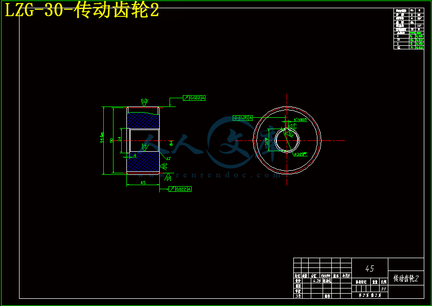
LZG-30-传动齿轮2.dwg
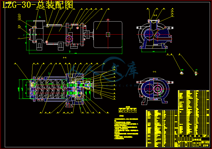
LZG-30-总装配图.dwg
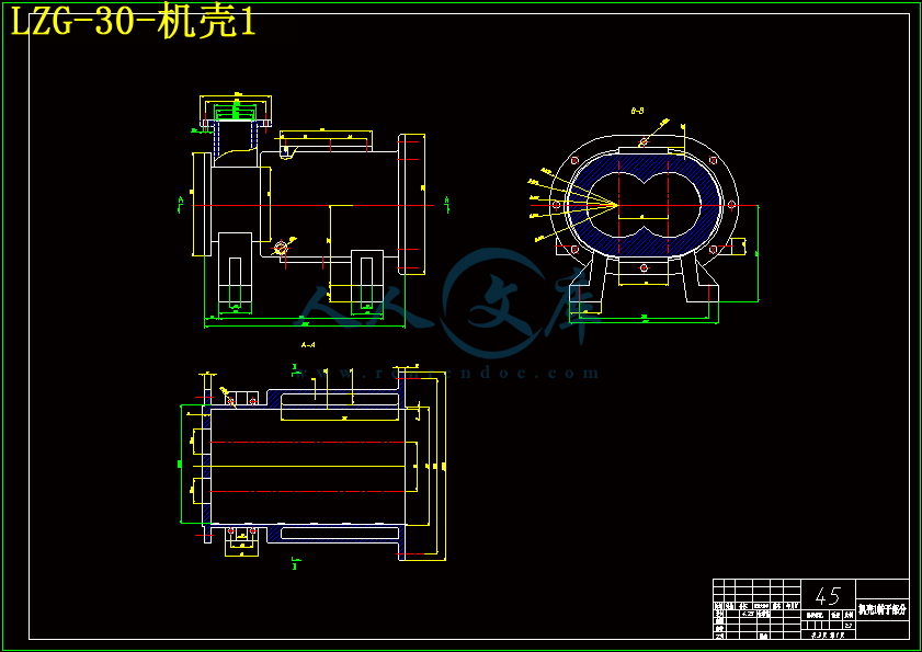
LZG-30-机壳1.dwg
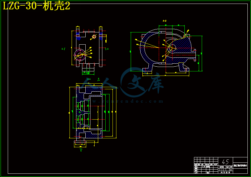
LZG-30-机壳2.dwg
LZG-30-机壳3.dwg
压缩包内文档预览:
预览图 预览图 预览图 预览图 预览图 预览图 预览图
编号:6037193    类型:共享资源    大小:5.21MB    格式:ZIP    上传时间:2017-10-25 上传人:俊****计 IP属地:江苏
40
积分
关 键 词:
lzg-30 螺杆 真空泵 建模 仿真 3d-sw 8张 cad 图纸 说明书
资源描述:

摘要

本文的研究对象,螺杆型干式真空泵,吸入腔没有任何工作液,保证了空间用泵无污染;没有油蒸汽排放,保证清洁的外部环境。由于转子齿面之间有间隙,因而可以抽除含有灰尘或腐蚀性的有毒气体。本课题主要集中在以下几个方面:基本原理的干式螺杆真空泵,阴阳转子螺杆型线的研究,螺旋型面线是单边等螺距型线,演绎数学的计算,建立几何模型面型线方程推导,然后螺旋齿面方程推导。几何特征研究等。

设计完成后应用solidworks软件做运动仿真对真空泵转子做三维建模,并且模拟转子运动展示其工作过程. 


关键词:干式螺杆真空泵 转子 型线 三维建模 运动仿真


Modeling?and?Simulation?of?                           LGZ-30?single?screw?dry?vacuum?pump

Abstract

The research object of this paper, Dry screw vacuum pump, The suction chamber with no working fluid, ensure the space is pumped from pollution; No oil vapor emissions, guarantee the clean of the external environment. Due to the gaps between the rotor tooth surface of Yin and Yang, thus it can be pumped in addition to containing dust, or corrosive, poisonous gases. The author studies mainly focus on the following aspects: the basic principles of dry screw vacuum pump. Yin and Yang screw type line of research. Screw type face line made bilateral symmetric circular arc line, deduce the mathematical expressions of meshing principle, establish geometric model face type line equation is deduced, and then screw tooth surface equation is deduced. Geometric characteristics research, etc. 

After the design is completed using SolidWorks software to do motion simulation to do 3D modeling of vacuum pump rotor. And the simulation of rotor motion display their works.

Keywords: dry screw vacuum pump rotor type line Three-dimensional modeling

Motion simulation 


目  录


绪  论 1

1  螺杆型干式真空泵的概述 2

1.1 课题背景及研究意义 2

1.2 螺杆真空泵在国内外的研究现状与发展方向 4

1.3 论文包括的主要内容 5

1.4 论文的组织结构 6

2  螺杆干式真空泵转子型线的研究 7

2.1 常见转子型线比较 7

2.2 单头等螺距矩形螺纹转子型线 8

2.2.1转子型线要素 8

2.2.2转子型线设计原则 9

2.2.3转子螺旋齿面方程 10

3  螺杆干式真空泵工作原理 12

3.1 吸气过程 12

3.2 压缩过程 12

3.3 排气过程 13

4  螺杆干式真空泵设计计算 14

4.1螺杆基本尺寸 14

4.2排气量 16

4.2.1理论排气量 16

4.2.2实际排气量 17

4.3进排气孔口 18

4.3.1轴向进气口 18

4.3.2轴向排气口 19

4.4极限真空度、功率及冷却水量 19

4.5轴的强度计算 20

4.6同步齿轮的设计计算 20

4.6.1齿轮尺寸计算 21

4.6.2齿轮强度校核 21

5  单头螺杆干式真空泵的应用 22

5.1 应用范围 22

5.2 抽气原理与结构 22

6 三维建模与运动仿真 23

6.1 SolidWorks介绍 23

6.2 转子三维建模 24

6.3 转子运动仿真 26

结  论 27

参考文献 28

致  谢 29


绪  论

1905年德国人沃尔夫岗.盖德发明了油封式旋片泵,从此各种以油为工作液、润滑剂、密封液的真空泵如雨后春笋般迅速普及,统治了真空设备市场近百年。从真空工业的视角来看,如果说20世纪是有油真空泵的世纪,那么21世纪将是干式真空泵的世纪。因为,各种形式的有油真空泵在工作过程中不可避免的随同排出的气体一起排出了大量的油污,这些油污能够严重的污染环境。随着利学技术的发展,要求提供比较清洁真空环境的真空工艺越来越多,甚至近于达到苛刻的要求,如微电子、化学、冶金、医疗、核聚变领域以及宇航、新材料的开发等技术领域.都要求提供比较洁的内真空环境。传统的有油泵很难满足这些要求,无油泵的概念便自然而然的在此基础上提出。有些工业过程,如低压气相沉积,会产生一些微小颗粒,这些颗粒在工作液中难以排除,它们可以使泵油污染,同样也会影响泵的抽气系统性能及使用寿命。而有些工业过程在运转中可能会使工作液冷凝成粘状物质,这样可能使泵卡住,甚至导致运转失效。又如对于食品工业为代表的一些特殊行业,这种污染更是非常不可取的。对于这些少数有着特殊需要的工业来说,就只能采用无油污的无油泵或水环式泵类(湿式泵),但这类泵的真空度不高,耗水耗能严重,而且相应的工作时带有大量的水汽,因此对于有干式要求的,又不得不采用繁琐的物理、化学吸附,冷凝低温手段,从而使成本变得极其昂贵。如:膜式泵,真空度不高,抽速小;吸附泵,不仅抽速小,液氮的费用也很大。所以可以这样说,在当时能直接排入大气和高真空机绍相连接的泵类各有其缺憾,因此导致了干式泵不适宜大工业的应用。


1  螺杆型干式真空泵的概述

1.1 课题背景及研究意义

干式螺杆真空泵是干式泵家族中的一员。所谓干式真空泵,一般认为是能在大气压到10Pa的压力范围内工作;在泵的抽气流道中,不能使用任何油类和液体,排气口与大气相通,能直接连续向大气中排气的泵,也称无油真空泵。

干式真空泵在抽气流道内无任何液态工作介质或密封介质,从根本上解决了油封式真空泵引发的各种问题。总的来说是两种不同的需求推动开发出两种类型的干泵。


内容简介:
Study on the performance prediction of screw vacuum pumpAbstractPumping characteristics of the screw vacuum pump were investigated. The aim of this study was to establish a method of the performance prediction and a way to design the pump that satisfies specific requirements. The performance was analysed by the balance among geometrical pumping speed, net throughput and leaks. The leaks flow through clearances between a screw rotor and a stator, and clearances between two meshing rotors. These leaks were estimated with the results based on the linearised BGK model and the flows through ideal labyrinthes. Experiments were carried out by rotors of 120 mm diameter, and pumping speed and ultimate pressure were measured. The comparison between the measurements and the predicted values shows that the present method predicts the performance of the screw pump with a sufficient accuracy for practical applications1. IntroductionIn recent years, screw vacuum pumps have become noticed, since the structure of the pump is simple and liquids or solids are hard to accumulate when sucked with gas or are condensed or solidified in the pump. An analytical model of screw vacuum pump will be useful to design a pump that satisfies specific requirements and to predict pumping characteristics under conditions which differ from the condition designed for. So, we propose an analytical model for the screw vacuum pump. 2. Outline of analytical modellingFig. 1 shows a pair of meshing rotors of the screw vacuum pump. The volume enclosed by a groove of screw, a crest of thread of another rotor and a stator traps gas and transfers it from inlet side to outlet side as the rotors rotate. The model is built by the balance among geometrical pumping speed, net throughput and leaks. Display Full Size version of this image (7K)Fig. 1. Configuration of the meshing rotors of screw vacuum pump. 2.1. Path of leaks inside the screw vacuum pumpThere are three kinds of clearances inside the screw pump, i.e. the clearance between rotor and stator O, the radial clearance between rotors I, and the axial clearance between rotors . In the case of single thread, paths of leaks which come into or out of the third transfer volume (appearing in Fig. 2A) for example, are as follows. Display Full Size version of this image (11K)Fig. 2. Clearance and flowing path of leak: (A) development of a pair of screws; (B) axial clearances. The leak through the axial clearance is considered as a superposition of the major component (represented by the straight arrow in Fig. 2B) and minor component (curved arrow). 2.2. Evaluating method of the leaksWe evaluate the leaks by a compound method. The method is compounded of the flow rate derived from BGK equations and diffuse reflections, and the flow rate of ideal labyrinthes. The leak through the clearance between rotor and stator, and the leak through the axial clearance between rotors are both given in the following form(1)and the leak through the radial clearance between rotors is given by(2)where MP is the mass flow rate of Poiseuille flow between parallel plates, MS mass flow rate through a slit, MC mass flow rate of Couette flow between parallel plates, MRp mass flow rate through a gap between two cylinders induced by pressure difference, MRr mass flow rate through a gap between two cylinders induced by rotation of the cylinders and ML mass flow rate of ideal labyrinthes. We obtained precise information on MP and MS from the studies of Hasegawa and Sone, and Sone and Itakura 3 and 6, respectively. MC is determined by the fact that the dimensionless flow rate equals a half, because of the anti-symmetry of the velocity. MRp and MRr are determined by(3)MRr= IUQRr (4)where RC=1/(1/R1+1/R2), U=(R1+R2). QRp and QRr are obtained by solving the MGL equation 1 by parabolic film approximation 2. The results are shown in Fig. 3. Display Full Size version of this image (4K)Fig. 3. Nondimensional mass flux through the gap between a cylinder and a plane. The axial clearance has a non-uniform gap, as shown in Fig. 4, then we define mean or representative quantity to apply the above evaluation methods. For example,(5)defines mean square clearance, where SM is the area of lens-like domain appearing in Fig. 4. The other definitions appear in the studies of Ohbayashi et al. 4 and 5. Display Full Size version of this image (3K)Fig. 4. Contour of the gap width of the axial clearance. 2.3. Pumping characteristicsAssuming that the pressure changes isothermally, the pressure pi in the ith transfer volume is represented by(6)where V is the volume of one transfer volume, MO leak rate through O, MI leak rate through I, MMb major component of the leak through , MMc minor component of the leak through via the minimum gap and iO,iI,iMb,iMc represent the differences between the number of upstream and downstream transfer volumes corresponding to the clearance or path indexed by subscript. Balance among geometrical pumping speed, net throughput and leaks leads to(7)where Tc represents one cycle of periodic pressure change. In the case that the screws are single threaded, Tc equals /, because the ith transfer volume comes to the (i+1)th position after half rotation. (6) and (7) can be solved under the following periodic condition:pi t=0=pi1 t=Tc, (i=1,2,3,nm) (8)3. ExperimentExperiments are carried out with a screw vacuum pump whose dimensions are shown in Table 1. Fig. 5a shows the comparison between measurements and analytical predictions relating to pumping speed. Fig. 5b shows the comparison relating to ultimate pressure as a function of rotating speed. The measurements and the predictions for ultimate pressure and pumping speed in the inlet pressure over the 100 Pa range are well agreed. Table 1. Dimensions of an experimental screw vacuum pump Display Full Size version of this image (10K)Fig. 5. Comparison between experimental results and analytical predictions: (a) pumping speed vs. inlet pressure; (b) ultimate pressure vs. rotation speed. 4. ConclusionsThe conclusions are summarised as follows: 1. the screw vacuum pump was analysed, and the analytical model of its pumping characteristics was proposed;2. the analytical model was verified through the experiments. This model has satisfying accuracy fo
温馨提示:
1: 本站所有资源如无特殊说明,都需要本地电脑安装OFFICE2007和PDF阅读器。图纸软件为CAD,CAXA,PROE,UG,SolidWorks等.压缩文件请下载最新的WinRAR软件解压。
2: 本站的文档不包含任何第三方提供的附件图纸等,如果需要附件,请联系上传者。文件的所有权益归上传用户所有。
3.本站RAR压缩包中若带图纸,网页内容里面会有图纸预览,若没有图纸预览就没有图纸。
4. 未经权益所有人同意不得将文件中的内容挪作商业或盈利用途。
5. 人人文库网仅提供信息存储空间,仅对用户上传内容的表现方式做保护处理,对用户上传分享的文档内容本身不做任何修改或编辑,并不能对任何下载内容负责。
6. 下载文件中如有侵权或不适当内容,请与我们联系,我们立即纠正。
7. 本站不保证下载资源的准确性、安全性和完整性, 同时也不承担用户因使用这些下载资源对自己和他人造成任何形式的伤害或损失。
提示  人人文库网所有资源均是用户自行上传分享,仅供网友学习交流,未经上传用户书面授权,请勿作他用。
关于本文
本文标题:LZG-30单头螺杆型干式真空泵的建模与仿真【3D-SW】【8张CAD图纸和说明书】
链接地址:https://www.renrendoc.com/p-6037193.html

官方联系方式

2:不支持迅雷下载,请使用浏览器下载   
3:不支持QQ浏览器下载,请用其他浏览器   
4:下载后的文档和图纸-无水印   
5:文档经过压缩,下载后原文更清晰   
关于我们 - 网站声明 - 网站地图 - 资源地图 - 友情链接 - 网站客服 - 联系我们

网站客服QQ:2881952447     

copyright@ 2020-2025  renrendoc.com 人人文库版权所有   联系电话:400-852-1180

备案号:蜀ICP备2022000484号-2       经营许可证: 川B2-20220663       公网安备川公网安备: 51019002004831号

本站为文档C2C交易模式,即用户上传的文档直接被用户下载,本站只是中间服务平台,本站所有文档下载所得的收益归上传人(含作者)所有。人人文库网仅提供信息存储空间,仅对用户上传内容的表现方式做保护处理,对上载内容本身不做任何修改或编辑。若文档所含内容侵犯了您的版权或隐私,请立即通知人人文库网,我们立即给予删除!