进度计划.xls

单臂液压铸造机设计【12张CAD图纸和说明书】

收藏

资源目录
跳过导航链接。
单臂液压铸造机设计【12张CAD图纸和说明书】.zip
进度计划.xls---(点击预览)
论文-单臂液压铸造机.doc---(点击预览)
英文翻译.docx---(点击预览)
开题报告.doc---(点击预览)
中文翻译.docx---(点击预览)
大螺母A3.dwg
总装.dwg
活塞头A4.dwg
活塞头螺母A3.dwg
活塞杆A3.dwg
液压原理图A3.dwg
液压缸A2.dwg
电机.dwg
电气原理图A2.dwg
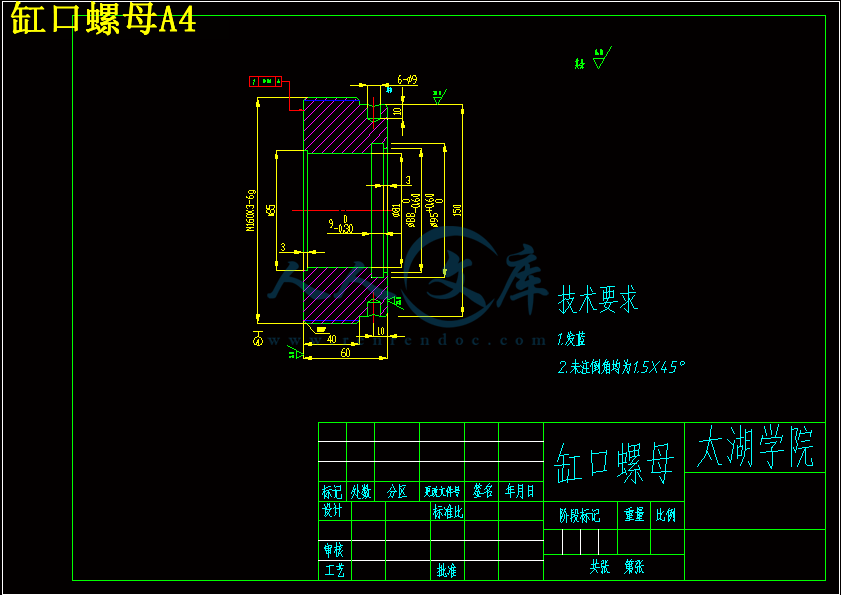
缸口螺母A4.dwg
缸套A3.dwg
集成块回路图A2.dwg
压缩包内文档预览:
预览图 预览图
编号:6037337    类型:共享资源    大小:3.79MB    格式:ZIP    上传时间:2017-10-25 上传人:俊****计 IP属地:江苏
40
积分
关 键 词:
液压 铸造 设计 12张 cad 图纸 说明书
资源描述:

摘  要

 作为现代机械设备实现传动与控制的重要技术手段,液压技术在国民经济各领域得到了广泛运用。作为世界加工中心,我国机械工业在国民经济中的基础作用越来越明显。液压机技术水平的高低直接影响到国家机械工业的发展水平。单柱式液压机是液压机产品的一个重要组成部分, 8000KN以下的小型锻造液压机常采用C型单臂机架,主要用于轴类零件、型材的校正和轴套类零件的装配,也可用于板材的弯曲成型、拉伸等工艺过程。配置一定的附件式模具后可进行粉末压制成型和固型塑料的成型压制,拥有自主的液压机设计技术是使国家机械工业能在世界竞争中取胜的重要保证,对其展开研究有重要的理论和实际意义。本文完成了160KN单柱式液压机本体的设计,并采用二维制图软件AutoCAD对其进行研究。论文提出了160KN单柱式液压机的技术参数,拟定了机器的结构形式,着重对工作缸做了结构设计和数据计算。根据液压机设计理论完成了整体机架结构及主要结构部件的设计与理论计算。对液压机本体的总体结构和关键部件进行了强度计算与分析,主要内容包括:结构中应力集中情况分析,初始设计方案修正,最终获得了满足强度和刚度要求的机架设计。最后利用AutoCAD软件对160KN单柱式液压机总装配图及主要零部件进行了设计,完成了液压机的整体结构设。


关键词:液压机;工作缸;强度


Abstract


As one of the important technical means to achieve the modern machinery equipment transmission and control, hydraulic technology has been widely used in the field of the national economy. As a processing center in the world, China's machinery industry foundation function in the national economy is more and more obvious. Hydraulic machine technology level directly affects the development level of the national machinery industry. Single column hydraulic machine is an important part of the hydraulic machine, small forging under 8000KN hydraulic press often uses the “C” type single arm frame, mainly used for shaft parts profile correction and sleeve parts assembly, can also be used for such as tensile plate bending forming process configuration must be the attachment type of mold powder can be suppressed after molding and plastic molding repression, hydraulic machine design technology with independent is an important guarantee to make the national machinery industry can win in the international competition, the expansion has important theoretical and practical significance to study. The design of the 160KN bulk single column hydraulic machine, and the use of 2D drawing software AutoCAD to study the. This paper presents the technical parameters of 160KN single column hydraulic machine, the structure of machine, the working cylinder structure design and calculation of the data. Design and theoretical calculation of the whole frame structure and the main part of the structure was completed according to the design theory of hydraulic machine. The key components of overall structure of the hydraulic machine body and gives the calculation and analysis of the strength, the main contents include: the stress concentration analysis of structure, modify the initial design scheme, finally satisfied frame design strength and stiffness requirements. At the end of the 160KN single column hydraulic machine assembly drawing and the main parts were designed by using AutoCAD software, completed the overall structure design of hydraulic machine.

Keywords: hydraulic machine;hydraulic cylinder;strength


目  录

摘  要 III

Abstract IV

目  录 V

1 绪论 1

1.1 课题背景及目的与意义 1

1.2 液压机的发展概况 1

1.2.1 液压机在现代工业中的地位 1

1.2.2我国液压机的现状及发展趋势 1

1.2.3 国外液压机的发展状况 3

1.2.4 液压机的总体发展趋势 4

1.3 液压机的工作原理和结构特点 4

1.3.1 液压机的工作原理 4

1.3.2 液压传动的优缺点 5

1.4 液压机的分类 6

2 液压机本体结构设计 8

2.1 液压机的结构特点及设计参数 8

2.1.1 液压机本体结构特点 8

2.1.2 160KN液压机的设计参数 8

2.2 上横梁结构的设计 9

2.3工作台结构的设计 9

2.3.1 结构形式 9

2.3.2 加工技术要求 10

2.3.3 固定模具的结构 10

3 液压机液压系统原理图设计 12

3.1 明确设计要求,制定基本方案 12

3.1.1 设计要求 12

3.1.2 确定液压执行元件的形式 12

3.1.3 确定液压执行元件运动控制回路 13

3.1.4 液压源系统 13

3.2 液压系统各液压元件的确定 13

3.2.1 液压介质的选择 13

3.2.2 拟定液压系统图 14

3.3 液压系统主要参数计算 16

3.3.1 选系统工作压力 16

3.3.2  液压缸设计中应注意的的问题 16

3.3.3 液压缸主要参数的确定 16

3.3.3 液压缸强度校核 17

3.3.4 液压缸稳定性校核 18

3.4 液压阀的选择 21

3.4.1 液压阀的作用 21

3.4.2 液压阀的基本要求 21

3.4.3 液压阀的选择 21

3.5 液压泵的选择 22

3.6 电动机功率的确定 22

3.7 液压管件的确定 23

3.7.1 油管内径确定 23

3.7.2 管接头 23

3.8 本章小结 23

4 液压机的强度与刚度计算 25

4.1 上横梁结构的强度与刚度计算 25

4.1.1 受力分析 25

4.1.2 主截面(Ⅰ—Ⅰ)强度计算 26

4.1.3 主截面(Ⅱ—Ⅱ)强度计算 26

4.2 本章小结 27

结  论 28

致  谢 29

参考文献 30


1 绪论

1.1 课题背景及目的与意义

通过160KN单柱液压机设计与计算,了解液压机的结构与工作原理,掌握液压机的设计计算步骤,以及液压缸和横梁的设计与计算方法。设计液压机的意义在于其不但具有较大的通用性,适用于塑性材料的成形如簿板件的落料、拉伸、压印等;轴类件的校正;零部件的压装;粉末制品的压制。还具有点动、手动和半自动等操作方式,可按工艺需要任选定时或定位控制,压力和行程可调,操作灵便、工作可靠。

1.2 液压机的发展概况

1.2.1 液压机在现代工业中的地位

流体传动与控制技术的主要代表液压技术自上世纪初面世以来,即“融合”到装备制造业中,成为其一个十分重要的基础领域,同时,液压技术将装备制造业作为其主要的应用领域,曾经引领着装备制造业一系列的技术进步[8]。因此液压技术对装备制造业而言,从来就有着较强的推动和影响作用,对装备制造业等诸多领域有着前置和后置效应,扮演着重要而关键的角色。21世纪初,中国装备制造业得益于国民经济持续发展的历史机遇,在诸多领域取得了重要的发展和技术进步,其中中国液压技术也扮演了重要的角色,并反映了它与时俱进的技术进步[5]。

液压机是利用液压传动技术进行压力加工的设备。它与机械压力机相比,具有压力和速度可在广泛的范围内无级调整,可在任意位置输出全部功率和保持所需压力,结构布局灵活,各执行机构动作可很方便地达到所希望的配合关系等等很多优点。同时液压元件具有高度的通用化、标准化特点,设计及制造均较为简单,所以液压机在国民经济各部门得到了日益广泛的应用[15]。

1.2.2我国液压机的现状及发展趋势

我国液压机的现状:我国液压技术的发展始于20世纪50年代,最初主要应用于机床和锻压设备上;20世纪60年代,我国从国外引进了一些液压元件生产技术,同时自行设计开发出了液压产品;20世纪80年代初期,我国又从美国、日本、德国引进了一些先进的技术和设备,是我国的液压技术水平有了很大的提高。目前,我国的液压元件已从低压到高压形成了系列产品,并开发生产出了许多新型的液压元件;在精度、重载大型设备的液压系统中,国产元件的应用也越来越多;行走机械液压系统中的专用液压元件也在大力开发。液压技术在我国经济建设和社会发展中将发挥越来越大的基础性和关键性的支撑作用[16]。下图1.1是滕州机械厂生产的单臂液压铸造机。


内容简介:
中文译文标题:数控简单剪切仪动态土壤测试作者:果皮,Pendo M,辉西斯图尔特,乔纳森P,加州大学洛杉矶分校Venugopal,拉维,Sysendes 公司。出版日期:01-01-2007系列:加州大学洛杉矶先前发表的作品发布信息:加州大学洛杉矶先前发表的作品,加州大学洛杉矶附加信息:版权 2007 年,ASTM,/原始引用:果皮,斯图尔特,摩根,d.h。,Venugopal,r .(2007)。“数控简单剪切设备动态土壤测试”,Geotech。测试日报,ASTM,30(5),368 - 377。数控剪切装置简单动态土壤测试文摘:我们描述的特征简单剪切装置能力运用现实的多向地震荷载对土标本。这个装置,文中称为数控简单剪切(直流 ss)装置,包括功能 ,如伺服液压控制的驱动和真正的数字控制克服控制的局限性,一些之前的动态土壤测试机器。该设备是显示有能力正弦和宽带的复制命令信号在一个广泛的频率和振幅,虽然设备有限控制能力非常小的命令位移(少于大约 0.005 毫米)。小变形限制结果从噪声介绍了控制系统的反馈信号的模数转换。我们证明,双向命令信号准确地传授与最小交叉耦合,结果从一个创新的多输入多输出的数字控制系统。这个功能的设备演示一系列宽带测试标本非饱和土受到 uni -和双向励磁。关键词:数字控制,简单的剪切、动态土壤测试、多向加载介绍直接简单的剪切设备已经成功运用多年来描述静态和动态土属性。这测试方法往往是首选当它是可取的标本来体验光滑、连续的旋转主应力方向在剪切。初始应力可以应用模拟静态字段条件当钢丝增强利用膜,减少横向变形样品(即。 ,NGI-type 配置,Bjerrum 和Landva1966)。也许最常见的应用程序的简单剪切试验对仿真的垂直(或近垂直)剪切波传播通过土柱。优点和局限性简单的剪切测试相对于其他类型的实验室测试描述了在其他地方,这里不再重复(比如,菜的 et al。1972;沈 et al。1978;萨达 et al。1982;Vucetic 和拉卡斯提花1982;1985;Budhu Bhatia et al。1985;Amer et al。1987;Airey 和木材 1987;Budhu 和 Britto 1987;雅 et al。 1993)。最简单的剪切设备运行在一个水平方向并应用谐波载荷频率一般慢于动态过程,如地震摇晃( 如。 ,Tatsuoka 和银 1981;Doroudian 和 Vucetic 1995;和 Pfender Lefebvre 1996;瑞艾莫和种子 1997;Kusakabe et al。1999 年,Hazirbaba 和 Rathje 2004)。虽然总是有近似参与应用在实验室土壤特性测量对现场条件,对现有设备无法提供快速、多向加载介绍进一步的错误未知的意义当实验室测量土壤属性用于工程模拟。一个数量的简单剪切设备已经被发展调查土壤响应多向加载(如。,石原和山崎 1980;雅et al。1993;DeGroot et al . 1996)。加州大学伯克利分校的双向循环简单剪切(UCB-2D)装置是值得注意的,因为它明显减少了机械合规问题,导致相对最高/基地帽摇摆在早期的设备(如。,石原和山崎 1980;石原和“1988) 。另一个显著的特点 UCB-2D 设备是燃烧室压力控制,方便背压饱和。校长 UCB-2D 设备本身的限制,早期的设备,是他们无法应用地震像宽带装货吗在快速位移率。这种限制也存在对大多数单向简单剪切设备。其原因是双重的:(1)气动加载系统使用一个可压缩流体(即。、空气 )其中介绍了重大错误的反馈回路在高频段;和(2)数字监督模拟控制器被雇用这有效地限制处理速度和成熟的控制算法。当然,振动台和离心机实验都能使用多方向的地震像加载到土壤模型( 即。,派克 et al。1975;1998 年 andYanagisawa Jafarzadeh 的说法;Kutter 1995;威尔逊 et al . 2004)。然而,直接测量土壤元素的响应(例如,剪切应力剪切应变关系、体积应变和孔隙水压力)在这些类型的实验需要密集的仪表数组 ,可以影响响应他们的目的是措施,从而使复杂数据解释(如。,困难 et al . 2005)。图 1应用的能力,可靠程度的控制,多向加载在一个很宽的频率范围内,土壤元素在实验室是至关重要的推进我们的根本理解动态土壤属性。例如,宽带装载能力是需要调查率影响土壤手稿收到 2006 年 3 月 1 日,1 月 28 日发表 2007 年,2007 年 5 月在线发表。1 研究生研究员,副教授和副主席,分别土木工程系& 大学环境工程加利福尼亚 ,洛杉矶,5731 年洛杉矶消沉大厅 CA 90095。2 工程师,指数失效分析,320 年,200 套房,欧文戈达德,CA92618 年。3 创始人和高级咨询顾问工程师,Sysendes,Inc .,1804 m, 套件 4、蒙特利尔、 QC H3H 1 硅陶瓷、加拿大的观点和结论包含在本文档的作者和不应被解释为一定代表官方的政策,明示或暗示,美国政府。岩土测试日报,卷。30,5 号纸 ID GTJ100518 可以在 368 年版权2007年由 ASTM 国际 ,100 年巴尔港驱动器,PO Box,西 Conshohocken C700,PA 19428 - 2959。属性,人们知道这是重要的对于粘土(如。,Lefebvre 和 Pfender 1996;Sheahan et al . 1996)。此外,效果剪切速率和 2 d 装载在孔隙压力生成或体积改变行为,或两者兼而有之,是了解较少,需要进一步调查一些土壤类型。为了满足这些研究需要,一个简单的剪切设备现场数控与能力室压力控制和多向激励一直发达。这个装置,文中称为现场数控简单剪切(直流 ss)装置合并功能,如伺服液压控制的驱动和真正的数字控制克服的局限性先前的动态土壤测试机器。结果是一个真正独特的简单剪切装置的功能应用宽带(地震像)位移要求土壤标本在两个方向,用最小的交叉耦合水平运动。在本文中,我们描述这个装置和它的功能动态土壤测试。物理描述直流 ss 装置机械设计的直流 ss 装置使用了 UCB-2D 的装置作为一个原型(面包师 et al . 1993)。这个直流 ss 装置是专为了保留的主要特征 UCB-2D 设备如包含细胞压力的目的背压饱和,有限的机械遵守尊重对简单剪切边界条件(如。,顶部和基板 “摇摆”), 和双向加载功能。除了这些特性,直流 ss 装置结合了几种改进设计相对于 UCB-2D 装置包括:我使用一个三邮报框架与高绩效跟踪轴承(容纳垂直位移的顶罩 ),以进一步降低摇摆 ;二世一个伺服液压控制的控制系统,使高频率加载;iii 双重轴负载细胞获得职位摩擦剪切载荷的测量。图 1 显示了大会的直流 ss 装置。照片的直流 ss 设备显示在图 2。直流党卫军的设备是用来测试圆柱土壤标本与直径 10.2 厘米或更少。这个标本是位于相对严格的底部和顶部帽(图 1、图 2(b)和通常局限由一线增强膜。见图 2(c),水平 (顶部和底部)面临的标本被限制的帽子,它含有细磨石 epoxied 变成一个休会覆盖整个脸的帽子除了保持嘴唇的铝在边缘。这些帽子提供一个“ 摩擦” 表面同时使排水进入多孔石头如果石头不饱和( 石头可以饱和对不排水试验) 。这个上盖/样品/下盖堆栈顶部之间的位置和底部适配器板图 1 所示。底部帽适合一个休息在底部适配器板。适配器板顶部轻轻地降低,这样休息在顶端的适配器板适合舒适地覆盖在顶盖。顶部和底部帽是紧紧在各自的适配器板由三个固定螺丝在每个板。一旦样品是获得两个适配器板之间,三个 LVDTs 间距分布样品安装在顶部适配器板和固定在板通过螺钉。这个标本是然后合并垂直应力和准备剪切载荷。图 2顶部适配器板是一种垂直表,进而是附加到一个垂直负载细胞(图 1)。垂直负载转移到标本通过垂直表,这是附加的三个等距线性幻灯片。每个三个线性幻灯片附属于一个单独的帖子,有效防止侧运动和摇摆的垂直表(因此,实际上无花果。 1 原理的直流 ss 装置在加利福尼亚大学洛杉矶分校。果皮 ET AL。在数控简单剪切仪 369 来说,标本) 。这是一个重要的三邮报框架改善 UCB-2D 设备 ,雇佣了一个悬臂系统(垂直表附加到一对跟踪轴承沿相同的墙)。负载应用于垂直表由气动执行机构安装在主框架之外。一个重要的功能的设备,直流党卫军留存从 UCB-2D 装置是其双向加载功能。横向剪切载荷应用在该基地的标本通过两个独立控制的水平表。底部水平表安装在线性幻灯片附加到主框架的装置,这表是只自由移动一个水平方向。上层水平表也安装在线性幻灯片,这样运动上层表是完全垂直于下表。两个水平表可以控制产生净合成的运动底部适配器板在任何水平方向。加载应用较低水平表通过螺纹棒相连致动器,可以应用张力和压缩。有一个 tensioncapable 辊之间连接上层表及其执行机构以适应垂直位移下表。负载应用到表 loadcells 来衡量安装执行机构和表之间。负荷测量由 loadcells 不相同,那些传授标本由于摩擦而在线性的幻灯片。这个巨大的摩擦加载系统中的表征,观察到相当小( 大约 2.2 N)。这一点的重要性摩擦负载取决于什么类型的测试,是理想的。这种摩擦负载将产生不准确的(大约 0.3 kPa10.2 厘米直径试样), 代表比例可以忽略不计的剪切应力对大多数应用程序。然而,如果很低应力测量是必要的,帖子摩擦剪切应力可以通过使用一个双轴 loadcell 测量。这种双轴 loadcell 适合在顶部之间适配器板和垂直表,一个空间,否则占用垫块。这种双轴 loadcell 能够测量两个垂直和剪切载荷同时以最小的相声这些通道之间。然而,存在的双轴 loadcell 介绍系统遵从性(即摇摆和垂直变形), 可能是重要的在大中型菌株。因此,大多数测试执行没有双轴 loadcell 到位。三 LVDTs(线性可变差动传感器),安装顶部和底部之间的适配器板,用于测量垂直标本变形。这些位置的 LVDTs 最小化错误由于机械合规。这三个 LVDTs 是用,这样相对摇摆的标本在两个方向的加载可以测量。三 LVDTs 数据的平均值定义试样高度在一个测试。水平变形是衡量两个 LVDTs 安装在水平表在吗正交的方向。设备的直流党卫军下运作的“应变控制”的条件下,这意味着表位移控制和执行机构力量必须实现这些位移测量。这个运动,可以传授表是有限的不同方面的控制系统对不同频段。在低频率 f0 24 赫兹,限制因素是峰致动器位移 umax = 51 毫米。在中间频率 0.24 Hzf15 赫兹,限制因素是流量的能力伺服阀的 Qmax = 158 立方厘米/ 秒。在频率 f15 赫兹,的制约因素是压力能力的液压泵 pmax = 21 MPa。的情况下谐波控制信号,这些数量可以与相关的峰值表动作如下:U(t) = D sin(wt) umax (1)u (t) = D w cos(wt) Qmax/A (2)u (t) = D w2sin(wt ) pmaxA/m (3) 图 3在 ut 及其衍生产品描述表位移 ,速度,和加速度,一个是执行机构的横截面积 20.3 平方厘米,m 是表质量 5.7 公斤,和频率表运动 (按弧度/ 秒) 。相应的峰值位移值,速度和加速度给出了图 3。控制系统能产生任何运动,是在的限制线在图 3。油柱的理论频率的致动器表系统给出了孔蒂和特龙贝蒂(2000):哪里是体积弹性模量的液压流体 1.7106 kPa 吗和 V 是原油的体积是 463 立方厘米的致动器。身体上,油柱频率代表自然频率的三液压执行器系统,它可以被可视化为表质量与弹簧连接有一个刚度定义的油柱在致动器室。对于命令信号频率油柱频率附近,表现为执行机构可以是有限的由于共振行为(如。,孔蒂和特龙贝蒂 2000)。直流 ss 控制系统如图 4 中,数字控制系统的直流党卫军设备有两个目的。第一个是提供控制信号直接驱动,驱动液压作动器 servovalves 为每个轴(直接驱动 servovalves 有机载控制器,纠正跟踪误差在控制信号在开车前液压致动器)。第二个目的是获得 LVDTs 数据和 loadcells。这里指的物理设备作为直流党卫军是最初开发了一个基于 pc 的数字监督模拟控制系统。这个控制系统使用 PID(比例-积分导数)控制算法,跑在一个 Windows操作系统。主要问题控制系统延时处理过程中的反馈信号从仪器(如(LVDT)和一代的命令信号。这限制了设备的能力,准确复制一些命令信号。这些问题尤其急性加载功能涉及快速度和 2 d 摇动。图 4该系统已成功用于以前的测试(例如,用力的 et al。2004;重击 et al。2005), 尽管这些应用程序涉及单向震动和 1.0 赫兹加载频率,所以控制问题相关的基于 pc 的系统没有显著的。控制系统目前设备使用一个系统所为硬实时数字控制。主要区别基于 pc 的数字控制是控制功能被实现在控制器板相对于个人电脑操作系统。这使保证采样频率的内部反馈回路的 5 kHz 使用位移反馈水平 LVDTs,而基于 pc 的数字监督模拟控制系统通常不能可靠地执行计算需要复杂的控制反馈采样频率高于 200 赫兹,根据处理器时钟速度,控制算法复杂,数量的后台进行由个人电脑操作系统等。数字控制系统利用两个 dSPACE DS1104 控制器板。每个板包含一个 PowerPC 603 e 处理器,四个 16 位 2 s 模拟数字(A / D)转换器,四个 12 位 A / D转换器 800 ns 和 8 个 16 位位十年代数模转换(D / A)转换器 ,除了其他输入/输出端口。这两个板安装在在一个 PCI 插槽主机电脑但运行他们自己的实时内核(即。,一个操作系统专门针对控制功能)独立于主机电脑的操作系统。一个 PID 控制算法实现了两个基于 pc 和硬实时数字控制。这被称为随后随着 “PID 控制器”。收益为 PID 控制器是调谐为获得最佳性能试错用阶梯函数命令信号。PID 控制器的输出是一个数字电压命令,发送到一个穆格公司电压放大器通过的 D / A 频道在 dSPACE 板。电压放大器,反过来,发送一个电压驱动信号到适当的执行机构伺服阀。见图 5(一个) 、PID控制的两个轴都是独立的,从而控制系统作为一个整体无法补偿对于交叉耦合效应(即:影响,运动沿一个轴在运动沿着第二轴)。图 5为了减少交叉耦合效应,数字控制系统是通过引入一个多输入多 multipleoutput 增强(MIMO)控制算法与 PID 控制器的接口。见图 5(b),该控制器采用线性差动变换器反馈两轴和生成一个补偿指令信号对于每个 PID 控制器,考虑到交叉耦合效果。控制器的设计和实现为一个离散状态空间系统使用 LQG(线性二次-高斯) 最优控制方法( 富兰克林 et al . 1990)。这方法需要估计的数量,反映四个经验系统属性。这是通过使用 N4SID 系统识别算法(Van Overschee 和德沼泽 1995)系统辨识算法操作输入-输出数据序列;用于此目的的数据是两个不相关的随机输入(生成的 PID 控制器)和相应的线性差动变换器输出信号。结合 MIMO 的控制算法,以及两个 PID 控制器是指后来的 “mimo PID”控制器。设备配置的直流党卫军,MIMO 算法可以打开或关闭。因此,要么 PID 或 mimo PID 吗数字控制的实验是可能的。数据采集功能无论是模式总结如下:输入运动时间步:不实用的下限;数量的输入运动数据点:不实用的上限;反馈采样频率( 即。,内部频率对反馈回路):5 kHz;数据记录频率:上界是 5 kHz,可以 downsampled 作为需要。直流 ss 系统性能性能的评价系统的直流党卫军(即。,控制器,泵、致动器、伺服阀), 两个谐波和宽带地震输入运动被指定为 PID 控制器和的控制器和由此产生的 mimo pid 反馈信号测量。单向测试进行评估性能每个轴的独立,并提供基线结果相互影响的评估。双向加载轴之间的交叉耦合进行评估。鸣谢开发的设备支持直流党卫军职业美国国家科学基金会的资助下,第二个作者(NSF 获奖号:9733113),亨利 Samueli 学校的工程和应用科学大学洛杉矶分校和美国地质调查显示,国家地震灾害减少计划,奖号。1434 - hg - 98 gr - 00037、05 hqgr0050 。这种支持是感激地承认。这个观点和结论包含在这个文档是作者的,不应该解释为一定代表官方的政策,要么表示或暗示,美国政府。帕特里克m史密斯和哈罗德卡斯珀是感谢他们的相当大的贡献发展的物理设备。我们感谢三匿名评论者对他们有用的手稿评论。无锡太湖学院毕 业 设 计 ( 论 文 )开 题 报 告题目: 单臂液压铸造机 信 机 系 机 械 工 程 及 自 动 化 专 业学 号: 0923115 学生姓名: 丁 剑 指导教师: 龚常洪(职称:副教授 )(职称: )2013 年 1 月 15 日 课题来源自拟题目科学依据(1)课题科学意义当代社会,制造业特别是机械制造业是国民经济的支柱产业,现代制造业正在改变着人们的生产方式、生活方式、经营管理模式乃至社会的组织结构和文化。由于中国潜在的巨大市场和丰富的劳动力资源,世界的制造业正在向中国转移,中国正在成为世界的制造大国。我国在家电等若干产品的产量已居世界第一位。但是在自主知识产权的创新设计、先进制造工艺和装备及现代化管理等方面仍然存在很大差距,所以我们还没还不是领先于世界的制造强国。机械制造业是国民经济和社会发展的物质基础,是一个国家综合国力的重要体现。伴随经济全球化,我国正在成为世界机械制造业的中心,但是与发达国家相比,我国机械制造业不仅制造工艺装备陈旧、生产自动化技术落后,企业管理粗放、缺乏自主创新产品与先进技术等,而且在快速、高品质、低成本,以及优质服务方面也有较大的差距。因此正确分析我国机械制造业的品牌优势、技术优势和成本优势,并依据不同类型制造业的特点,有针对性地提出制造业的信息化战略对策具有重要意义。(2)单臂液压铸造机的研究状况及其发展前景设计液压机的意义在于其不但具有较大的通用性,适用于塑性材料的成形如簿板件的落料、拉伸、压印等;轴类件的校正;零部件的压装;粉末制品的压制。还具有点动、手动和半自动等操作方式,可按工艺需要任选定时或定位控制,压力和行程可调,操作灵便、工作可靠。目前我国生产的液压铸造机的市场占有率跟国外生产的是无法比拟的。在安全性方面,国外某些采用微处理器控制的高性能液压机利用软件进行故障的检测和维修,产品可实现负载检测、自动模具保护和错误诊断等功能。为了促进液压铸造机的发展,应深入研究和探讨下列几个问题,即发展前景:(1)实现高速化、高效化、低能耗、机电液一体化、自动化、智能化、液压元件集成化,标准化;(2) 改进液压机的性能、提高稳定性、加工效率等。研究内容 设计 一台 16T “C”型单臂液压铸造机,方案可行,机构合理,经济实用,并满足给定的设计技术条件。 液压铸造机总体设计方案确定,绘制总体布局图; 液压缸设计和计算; 横梁的设计,绘制单臂“C”型液压机装配图、零部件图 ; 拟采取的研究方法、技术路线、实验方案及可行性分析实验方案设计一台“C”单臂液压铸造机,主要用于轴类零件、型材的校正和轴套类零件的装配,也可用于板材的弯曲成型、拉伸等工艺过程。配置一定的附件式模具后可进行粉末压制成型和固型塑料的成型压制。确定该液压铸造机各个部件及其行程安排,完成该铸造机的传动选择以及总体布局设计。利用液压缸,驱动电机为主要器件,运用液压原理和材料力学知识进行强度、稳定性的校核研究计划及预期成果研究计划:2012 年 10 月 28 日-2012 年 11 月 28 日:学习并翻译一篇与毕业设计相关的英文材料。2012 年 12 月 01 日-2012 年 12 月 30 日:按照任务书要求查阅论文相关参考资料,完成绪论,填毕业设计开题报告书。2013 年 12 月 10 日-2013 年 03 月 10 日:填写毕业实习报告。2013 年 02 月 20 日-2013 年 03 月 20 日:按照要求修改毕业设计开题报告。2013 年 03 月 20 日-2013 年 04 月 30 日:单臂液压铸造机设计。2013 年 05 月 01 日-2010 年 05 月 21 日:毕业论文撰写和修改工作。预期成果:这套低成本、高效率、高可靠性、人性化单臂液压铸造机,能在市场竞争中处于有利地位。液压控制技术的应用范围广泛,其推广应用社会经济效益十分显著,国内制造业水平有显著的提高。特色或创新之处运用液压技术,效果明显,方便加工生产,能有效的提高加工生产效率。采用固定某些参量、改变某些参量来研究问题的方法,思路清晰,简洁明了,行之有效。已具备的条件和尚需解决的问题图书馆中提供了大量的资料,包括前辈们辛苦的劳动成果,使得我可以像站在巨人肩膀上一样来设计课题,当然,由于学生的条件约束性,不能到工厂进行实际装配操作,理论依据也有待完善。指导教师意见指导教师签名:年 月 日 教研室(学科组、研究所)意见教研室主任签名:年 月 日系意见主管领导签名年 月 日 英文原文Title:Digitally controlled simple shear apparatus for dynamic soil testingAuthor:Duku, Pendo M, Fugro WestStewart, Jonathan P, University of California, Los AngelesVenugopal, Ravi, Sysendes, Inc.Publication Date:01-01-2007Series:UC Los Angeles Previously Published WorksPublication Info:UC Los Angeles Previously Published Works, UC Los AngelesAdditional Info:Copyright 2007, ASTM, /Original Citation:Duku, P.M., Stewart, J.P., Whang, D.H., Venugopal, R. (2007). “Digitally controlled simple shearapparatus for dynamic soil testing,” Geotech. Testing Journal, ASTM, 30 (5), 368-377.Digitally Controlled Simple Shear Apparatus forDynamic Soil TestingABSTRACT:We describe the characteristics of a simple shear apparatus capable of applying realistic multidirectional earthquake loading to soilspecimens. This device, herein termed the Digitally Controlled Simple Shear (DC-SS) apparatus, incorporates features such as servohydraulicactuation and true digital control to overcome control limitations of some previous dynamic soil testing machines. The device is shown to be capableof reproducing sinusoidal and broadband command signals across a wide range of frequencies and amplitudes, although the device has limitedcontrol capabilities for very small command displacements (less than approximately 0.005 mm). The small deformation limitation results from noiseintroduced to the control system from analog-to-digital conversion of feedback signals.We demonstrate that bidirectional command signals can beaccurately imparted with minimal cross coupling, which results from an innovative multiple-input, multiple-output digital control system. Thecapabilities of the device are demonstrated with a series of broadband tests on unsaturated soil specimens subjected to uni- and bidirectional excitation.KEYWORDS: digital control, simple shear, dynamic soil testing, multidirectional loadingIntroductionDirect simple shear apparatuses have been utilized successfully formany years to characterize static and dynamic soil properties. Thismethod of testing is often preferred when it is desirable for thespecimen to experience a smooth and continuous rotation of theprincipal stress directions during shear. Initial stresses can be applied to simulate at-rest field conditions when wire reinforcedmembranes are utilized that minimize lateral distortion of thesample (i.e., the NGI-type configuration, Bjerrum and Landva1966). Perhaps the most common application of simple shear testing has been for the simulation of vertical (or nearly vertical) shearwave propagation through a soil column. Advantages and limitations of simple shear tests relative to other types of laboratory tests have been described elsewhere and are not repeated here (e.g.,Lucks et al. 1972; Shen et al. 1978; Saada et al. 1982; Vucetic and Lacasse 1982; Budhu 1985; Bhatia et al. 1985; Amer et al. 1987; Airey and Wood 1987; Budhu and Britto 1987; Boulanger et al. 1993).Most simple shear apparatuses operate in a single horizontal direction and apply harmonic loading at frequencies which are typically slower than dynamic processes such as earthquake shaking (e.g., Tatsuoka and Silver 1981; Doroudian and Vucetic 1995; Lefebvre and Pfender 1996; Riemer and Seed 1997; Kusakabe et al. 1999; Hazirbaba and Rathje 2004). While there are always approximations involved in applying soil properties measured in the laboratory to field conditions, the inability of existing devices to provide rapid, multidirectional loading introduces further errors of unknown significance when laboratory-measured soil properties are used in engineering simulations. A number of simple shear apparatuses have been developed to investigate soil response to multidirectional loading (e.g., Ishihara and Yamazaki 1980; Boulanger et al. 1993; DeGroot et al. 1996). The University of California, Berkeley bidirectional cyclic simple shear (UCB-2D) device is noteworthy since it significantly reduced mechanical compliance issues that caused relative top/base cap rocking in earlier devices (e.g., Ishihara and Yamazaki 1980; Ishihara and Nagase 1988). Another significant feature of the UCB-2D device is chamber pressure control, which facilitates back pressure saturation .The principal limitation of the UCB-2D device, and earlier devices, is their inability to apply earthquake-like broadband loading at rapid displacement rates. This limitation also exists for most unidirectional simple shear devices. The reasons for this are twofold :(1) pneumatic loading systems use a compressible fluid (i.e., air) which introduces significant errors to the feedback loop at high frequencies; and (2) digitally-supervised analog controllers were employed which effectively limit the processing speed and sophistication of the control algorithms. Of course, shaking table and centrifuge experiments are capable of applying multidirectional earthquake-like loading to soil models (i.e., Pyke et al. 1975;Jafarzadeh andYanagisawa 1998; Kutter 1995;Wilson et al. 2004).However, direct measurements of the soil element response (e.g.,shear stress-shear strain relationships, volumetric strain, and porewater pressure) in these types of experiments requires dense instrumentationarrays that can affect the response they are intended to measure, which in turn complicates data interpretation (e.g., Elgamal et al. 2005). The capability of applying, with a reliable degree of control, multidirectional loading across a wide range of frequencies to soil elements in the laboratory is critical to advancing our fundamental understanding of dynamic soil properties. For example, broadband loading capabilities are needed to investigate rate effects on soil properties, which are known to be significant for clays (e.g., Lefebvre and Pfender 1996; Sheahan et al. 1996). Moreover, the effect of shear rate and 2D loading on pore pressure generation or volume change behavior, or both, is less well understood and requires further investigation for some soil types.To meet these research needs, a digitally-controlled simple shear device with capabilities for chamber pressure control and multidirectional excitation has been developed. This device, herein termed the Digitally-Controlled Simple Shear (DC-SS) apparatus incorporates features such as servohydraulic actuation and true digital control to overcome the limitations of previous dynamic soil testing machines. The result is a truly unique simple shear apparatus with the capability to apply broadband (earthquake-like) displacement demands on soil specimens in two directions and with minimal cross coupling between the horizontal motions. In this paper, we describe this device and its capabilities for dynamic soil testing. Physical Description of DC-SS DeviceThe mechanical design of the DC-SS device was developed using the UCB-2D device as a prototype (Boulanger et al. 1993). The DC-SS device was designed to retain the main features of the UCB-2D device such as inclusion of cell pressure for purposes of back pressure saturation, limited mechanical compliance with respect to simple shear boundary conditions (e.g., top and base platen “rocking”), and bidirectional loading capability. In addition to these features, the DC-SS device incorporates several design improvements relative to the UCB-2D device including: _i_ the use of a tri-post frame with high performance track bearings (which accommodate vertical displacements of the top cap) to further reduce rocking; _ii_ a servohydraulic control system to allow for high frequency loading; and _iii_ a dual axis load cell to obtain post-friction shear load measurements.Figure 1 shows the general assembly of the DC-SS apparatus. Photographs of the DC-SS device are shown in Fig. 2. The DC-SS device was designed to test cylindrical soil specimens with a diameter of 10.2 cm or less. The specimen is located between relatively rigid bottom and top caps (Fig. 1, Fig. 2(b) and is typically confined by a wire reinforced membrane. As shown in Fig. 2(c), the horizontal (top and bottom) faces of the specimen are confined by the caps, which contain fine porous stones epoxied into a recess covering the entire face of the cap except for a retaining lip of aluminum around the edge. These caps provide a “frictional” surface while allowing for drainage into the porous stones if the stones are unsaturated (the stones can be saturated for undrained tests). The top cap/specimen/bottom cap stack is positioned between the top and bottom adapter plates shown in Fig. 1. The bottom cap fits into a recess within the bottom adapter plate. The top adapter plate is gently lowered such that a recess within the top adapter plate fits snugly over the top cap. The top and bottom caps are held tightly on their respective adapter plates by three set screws on each plate. Once the specimen is secured between the two adapter plates, three LVDTs equally spaced around the specimen are mounted on the top adapter plate and fixed to the plate by set screws. The specimen is then consolidated by a vertical stress and is ready for shear loading. Above the top adapter plate is a vertical table, which in turn is attached to a vertical load cell (Fig. 1). Vertical loads are transferred to the specimen through the vertical table, which is attached to three equally spaced linear slides. Each of the three linear slides is attached to a separate post, which effectively precludes lateral movements and rocking of the vertical table (and hence, practically speaking, the specimen as well). This tri-post frame is a significant improvement over the UCB-2D device, which employed a cantilever system (vertical table attached to a pair of track bearings along the same wall). Loads are applied to the vertical table by a pneumatic actuator mounted outside the main frame.An important feature of the DC-SS device that was retained from the UCB-2D device is its bidirectional loading capability. Horizontal shear loads are applied at the base of the specimen through two independently controlled horizontal tables. The bottom horizontal table is mounted on linear slides attached to the main frame of the apparatus, and this table is free to move in only one horizontal direction. The upper horizontal table is also mounted on linear slides such that the movement of the upper table is exactly perpendicular to the lower table. The two horizontal tables can be controlled to produce net resultant movements of the bottom adapter plate in any horizontal direction. Loads are applied to the lower horizontal table by threaded rods that are attached to an actuator that can apply tension and compression. There is a tensioncapable roller connection between the upper table and its actuator to accommodate perpendicular displacements of the lower table. The loads applied to the tables are measured by loadcells mounted between the actuators and the tables. The loads measured by the loadcells are not identical to those imparted to the specimen due to friction in the linear slides. The magnitude of the frictional load within the system was characterized and observed to be quite small (approximately 2.2 N). The significance of this frictional load is dependent on what type of testing is desired. This frictional load will produce inaccuracies of approximately 0.3 kPa (for a10.2-cm diameter specimen), which represents a negligible percentage of the shear stress for most applications. However, if very low stress measurements are needed, post-friction shear stresses can be measured by using a dual-axis loadcell. The dual-axis loadcell fits in between the top adapter plate and the vertical table, a space which is otherwise occupied by a spacer block. The dual-axis loadcell is capable of measuring both the vertical and shear loads simultaneously with minimal cross talk between these channels. However, the presence of the dual-axis loadcell introduces system compliance (i.e., rocking and vertical deformations) that may be significant at medium to large strains. Therefore, most tests are performed without the dual-axis loadcell in place.Three LVDTs (linear variable differential transducers), mounted between the top and bottom adapter plates, are used to measure the vertical specimen deformations. These locations of LVDTs minimize errors due to mechanical compliance. The three LVDTs are used so that relative rocking of the specimen in either direction of loading can be measured. Data from the three LVDTs are averaged to define specimen height during a test. Horizontal deformations are measured by two LVDTs mounted to the horizontal tables in orthogonal directions. The DC-SS device operates under “strain-control” conditions, meaning that table displacements are controlled and the actuator forces required to achieve those displacements are measured. The motions that can be imparted to the tables are limited by different aspects of the control system for different frequency bands. At low frequencies , the limiting factor (0.24Hz)is the peak actuator displacement (Umax=51 mm). At intermediate frequenciesthe limiting factor is the flow rate capacity of the servo-valve (0.2415)(_Qmax=158 cm3/s). At frequencies (f 15 )Hz, the limiting factor is the pressure capacity of the hydraulic pump (Pmax=21 MPa)_. For the case of harmonic control signals, these quantities can be related to the peak table motions as follows:(1)()=()Qmax/A (2)()=()U(t) -D sin(wt) (3)2= 2 /where U(t) and its derivatives describe the table displacement, velocity, and acceleration, A is the cross-sectional area of the actuator( 20.3 cm2), m is the table mass( 5.7 kg), and _ is the frequency of table motion (in radians/s). The corresponding peak values of displacement, velocity, and acceleration are given in Fig. 3. The control system is capable of producing any motion that lies below the limit lines in Fig. 3.DC-SS Control SystemAs illustrated in Fig. 4, the digital control system for the DC-SS device serves two purposes. The first is to provide control signals to direct drive servovalves that drive hydraulic actuators for each axis (direct drive servovalves have an onboard controller that corrects tracking errors in the control signal before driving the hydraulic actuators). The second purpose is to acquire data from the LVDTs and loadcells. The physical device referred to here as DC-SS was originally developed with a PC-based digitally-supervised analog control system. This control system used a PID (Proportional- Integral-Derivative) control algorithm that ran within a Windows operating system. The principal problem with that control system was latency in the processing of feedback signals from instruments (such as an LVDT) and the generation of command signals. This limited the ability of the device to accurately replicate some command signals. These problems were especially acute for loading functions involving fast velocities and 2D shaking. The system was successfully used in previous testing (e.g., Whang et al. 2004; Whang et al. 2005), although those applications involved unidirectional shaking and a 1.0 Hz loading frequency, so control problems associated with the PC-based system were not significant.The control system for the present device uses a system referred to as hard real-time digital control. The principal difference from PC-based digital control is that the control functions are implemented on the controller board as opposed to a PC operating system. This enables guaranteed sampling frequencies for the internal feedback loop of 5 kHz using displacement feedback from the horizontal LVDTs,whereas PC-based digitally-supervised analog control systems typically cannot reliably execute the computations required for complex control at feedback sampling frequencies higher than 200 Hz, depending on the processor clock speed, control algorithm sophistication, number of background processes handled by the PC operating system, etc. The digital control system utilizes two dSPACE DS1104 controller boards. Each board contains a PowerPC 603e processor, four 16-bit 2 _s analog-to-digital (A/D) converters, four 12-bit 800 ns A/D converters and eight 16 -bit 10 _s digital-to-analog (D/A) converters, in addition to other input/output ports. The two boards are mounted in PCI slots in a host PC but run their own real-time kernel (i.e., an operating system specifically tailored for control functions) independent of the host PCs operating system.A PID control algorithm was implemented for both PC-based and hard real time digital control. This is referred to subsequently as the “PID controller”. Gains for the PID controller are tuned by trial-and-error for optimal performance using a step function command signal. The output of the PID controller is a digital voltage command that is sent to a Moog voltage amplifier via one
温馨提示:
1: 本站所有资源如无特殊说明,都需要本地电脑安装OFFICE2007和PDF阅读器。图纸软件为CAD,CAXA,PROE,UG,SolidWorks等.压缩文件请下载最新的WinRAR软件解压。
2: 本站的文档不包含任何第三方提供的附件图纸等,如果需要附件,请联系上传者。文件的所有权益归上传用户所有。
3.本站RAR压缩包中若带图纸,网页内容里面会有图纸预览,若没有图纸预览就没有图纸。
4. 未经权益所有人同意不得将文件中的内容挪作商业或盈利用途。
5. 人人文库网仅提供信息存储空间,仅对用户上传内容的表现方式做保护处理,对用户上传分享的文档内容本身不做任何修改或编辑,并不能对任何下载内容负责。
6. 下载文件中如有侵权或不适当内容,请与我们联系,我们立即纠正。
7. 本站不保证下载资源的准确性、安全性和完整性, 同时也不承担用户因使用这些下载资源对自己和他人造成任何形式的伤害或损失。
提示  人人文库网所有资源均是用户自行上传分享,仅供网友学习交流,未经上传用户书面授权,请勿作他用。
关于本文
本文标题:单臂液压铸造机设计【12张CAD图纸和说明书】
链接地址:https://www.renrendoc.com/p-6037337.html

官方联系方式

2:不支持迅雷下载,请使用浏览器下载   
3:不支持QQ浏览器下载,请用其他浏览器   
4:下载后的文档和图纸-无水印   
5:文档经过压缩,下载后原文更清晰   
关于我们 - 网站声明 - 网站地图 - 资源地图 - 友情链接 - 网站客服 - 联系我们

网站客服QQ:2881952447     

copyright@ 2020-2025  renrendoc.com 人人文库版权所有   联系电话:400-852-1180

备案号:蜀ICP备2022000484号-2       经营许可证: 川B2-20220663       公网安备川公网安备: 51019002004831号

本站为文档C2C交易模式,即用户上传的文档直接被用户下载,本站只是中间服务平台,本站所有文档下载所得的收益归上传人(含作者)所有。人人文库网仅提供信息存储空间,仅对用户上传内容的表现方式做保护处理,对上载内容本身不做任何修改或编辑。若文档所含内容侵犯了您的版权或隐私,请立即通知人人文库网,我们立即给予删除!