外文文献.doc

裹包机横封装置设计【三维UG零件】【7张CAD图纸和说明书】

收藏

资源目录
跳过导航链接。
裹包机横封装置设计【三维UG零件】【7张CAD图纸和说明书】.zip
说明书.doc---(点击预览)
封面.doc---(点击预览)
UG三维图
fengkoudao 13.prt
fengkoudao 16.prt
qieduanshangdao15.prt
qieduanxiadao14.prt
zhou2.prt
zhou6.prt
相关资料
A0-装配图.dwg
A3-上封口刀.dwg
A3-上轴.dwg
A3-下封口刀.dwg
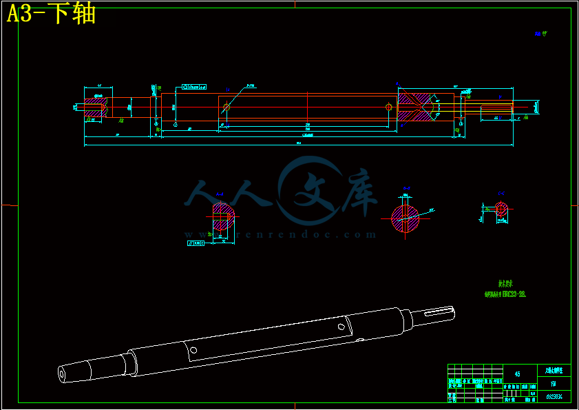
A3-下轴.dwg
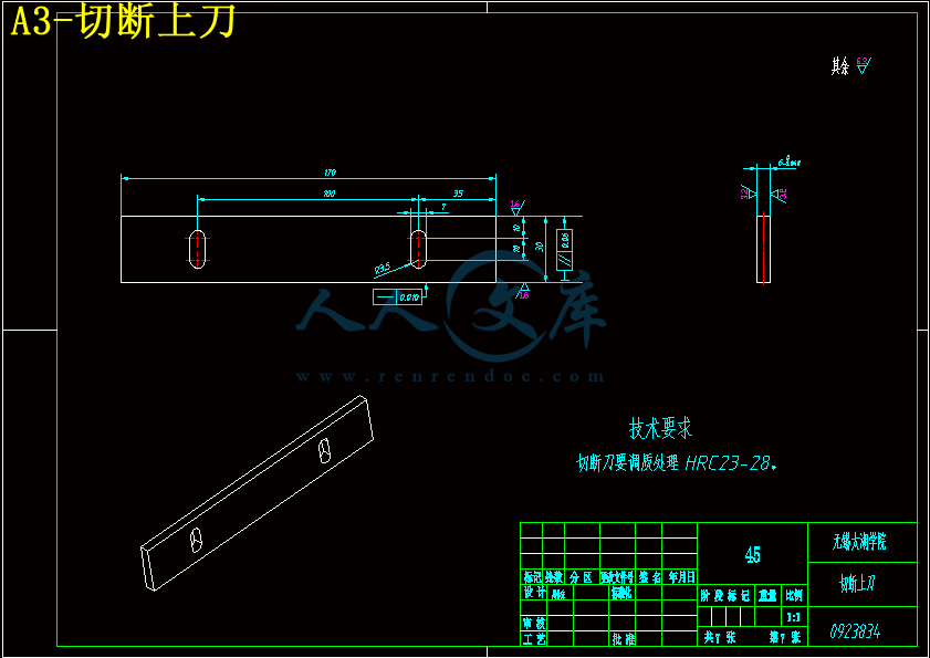
A3-切断上刀.dwg
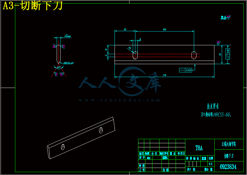
A3-切断下刀.dwg
压缩包内文档预览:
预览图 预览图 预览图 预览图 预览图 预览图 预览图 预览图
编号:6039140    类型:共享资源    大小:5.24MB    格式:ZIP    上传时间:2017-10-26 上传人:俊****计 IP属地:江苏
40
积分
关 键 词:
包机 封装 设计 三维 ug 零件 7张 cad 图纸 说明书
资源描述:

摘要


食品包装机械,是指能够完成全部或部分的产品和食品包装过程的机械,包装的过程有填充物料、裹包、封口等主要工序,以及与之相关联的前后工序,如清洗、堆码等。此外,包装还包含计量或在包装件上盖印等工序。使用机械包装的产品可提高生产效率,减轻劳动的强度,适应大规模生产需要,且满足清洁卫生要求。目前国内生产的设备大多是对国外进口设备的简单仿制,同时我国的包装机械产品也普遍存在质量的不好、性能单一、成本较高、技术含量较低的状况。因此对食品自动包装机械关键部件的深入研究,对原理、功能、结构、运动等分析,提供结构简单可靠、自动化程度高、操作方便、用途范围广的包装机很有必要的。

本文在分析方便面自动包装机的包装工艺和使用要求的基础上,通过对关键部件的理论分析,提出一种实用、简单的横封机构,实现了根据薄膜厚度不同自动调节加热时间和温度的功能,并且对方便面包装机封切机构的机构,工作原理及各组成部分功能做了较为详细的研究和设计,对关键部分提出完整的设计方法和造型设计,旨在满足市场需求,推动企业创新步伐。

本文借助了UG、CAD等软件分析运动规律和结构设计,这种利用计算机辅助设计和分析的方法,可以应用与其它类型包装设备的设计和分析中。


关键词:包装机械;封切机构;包装工艺;机构设计


Abstract


Food packaging machinery is able to complete all or part of the products and food packing process machinery, packaging process, including filling, wrapping, sealing and other major process, and the associated processes before and after, such as cleaning, stacking, and demolition. In addition, the packaging also includes a measurement or on the package stamped and other process. The use of mechanical packaging products to increase productivity, reduce labor intensity, to meet the needs of the large-scale production, and meet the requirements of hygiene, at present , domestic equipment is mostly a simple imitation of the imported product. Also, prevalence of inconsistent quality, and performance of a single, high cost, low technical content and packaging machinery products in China situation. Therefore, in-depth study of the key components of food-automatic packaging machine, the principle, structure, movement , functional analysis. Provide a simple and reliable structure, convenient operation, high degree of automation is necessary to use a wide range of packaging machines.

This article based on analysis of instant noodles, automatic packing machine packaging technology and use requirements. By means of the theoretical analysis of the key components, propose a practical, simple cross-seal mechanism, realized the function automatically adjusts the heating time and temperature according to the film thickness, and instant noodles packaging machine sealing and cutting to the structure, working principle and part of the functional to do a more detailed study and design. The key components of a complete design methodology and design, designed to meet the market demand, to promote the pace of business innovation.

In this paper, using the AUTOCAD, UG, such as movement of software analysis and structural design, such as the use of computer-aid design and analysis methods can be applied to other types of packaging equipment design and analysis.


Key words: Packaging Machinery; Sealing and Cutting institutions; Packing technology; Mechanism Design


目录

摘要 III

Abstract IV

1 绪论 1

1.1 课题的来源 1

1.2 本课题设计的目的意义 1

1.2.1 设计的目的及研究的内容 1

1.2.2 设计的意义 1

1.3 本设计的发展方向与存在的问题 2

1.3.1 设计的方向 2

1.3.2 设计存在的问题 2

1.3.3 研究的内容和方法 2

2 总体方案设计 5

2.1 主要组成结构 5

2.2 主要技术参数 5

2.3 横封装置的工作原理 7

2.4 横封的工艺要求 7

2.5 适用范围 8

3 传动机构设计 9

3.1 偏心链轮 9

3.1.1 偏心链轮运动规律的分析 9

3.1.2 计算设计 10

3.2 齿轮的设计 12

4 横封装置设计 17

4.1 弹簧的选择 17

4.2 热封头的设计 18

4.3 轴承的设计 19

4.3.1 轴承的选择 19

4.3.2 轴承的润滑及密封 19

4.3 轴的设计与计算 20

5 使用和维护保养 25

5.1 安全操作规程 25

5.2 封口质量的调整 25

5.3 常见故障及排除方法 25

5.4 维护清洁与保养 25

6 三维软件的应用 27

6.1 三维软件的介绍 27

6.2 CAD模块 27

6.3 UG在横封装置设计中的使用 27

7 结论与展望 31

7.1 结论 31

7.2 不足之处及未来展望 31

致  谢 32

参考文献 33


1 绪论

1.1 课题的来源    

随着市场经济的发展,人民生活水平的不断提高,包装机械工业在国民经济中所占作用和比重也越来越大。一方面显示出工业化生产发展的高速,另一方面又显示出人们在追求商品质量的同时,对商品的包装要求也越来越高。这一切为推动包装机械行业带来了巨大的动力。 综观世界范围来看,包装机械工业是一个市场潜力巨大的新兴产业,尤其是在最近几年发展极其迅猛,已经在各国国民经济中占用重要的地位。它可以提高劳动生产效率,改善生产的环境,降低生产的成本,提高商品的档次,增加商品的附加值,从而增强商品的市场竞争力、社会效益和经济效益。目前,美国、日本、德国、意大利是世界包装机械的四大强国,这些国家生产的包装机械产品品种多、数量大,在国际市场上有着较高的占有率。 目前包装机械发展的总趋势是发展重点趋向于能耗低、结构紧凑、重量轻、占地空间小、效率高的产品包装机。这在国外体现为现代化先进包装机械的高新技术,他们将机械技术与微电子技术和信息技术结合,开发数字化、智能化、柔性化的新型包装机械产品。在国内,包装机械行业的发展趋势是在引进、消化、吸收的基础上,已经有一定创新,产品的科技含量在不断的提高,这些包装机械产品正在向机电结合、主辅机结合、成套连线的方向发展。但是,包装机械产品在开发的过程中也存在一定的问题,主要是如何面对国外企业及外资企业的竞争,如何根据中国的国情,提高产品的“三化”水平,做到生产的高速化,包装产品规格的多样化,提高产品的可靠性及如何使食品和药品的包装机达到无菌化。而这些需要我们抓紧包装机械的研究,不断的开发新的技术,这样才能加快国内包装机械技术的提升。 

1.2 本课题设计的目的意义 

1.2.1 设计的目的及研究的内容     

商品包装是一个朝阳行业,是在市场竞争日趋激烈、商品经济日益繁荣的新形式下,逐步成长起来的。在商品的流通过程中,袋装商品的包装要求主要有两个方面,一是要求包装美观,以便吸引顾客,并保证商品在流通中包装袋不会出现任何形式的破损。其二是要求包装袋内的商品要计量准确,误差要小(包装机械行业的标准要求计量误差要小于5‰),以便维护商品生产厂商的信誉和形象。因此商品包装的精确计量,是包装行业内时刻关注的一项重要课题。

1.2.2 设计的意义 

目前市场上的包装机种类繁多,性能各异,面对品种繁多的商品自动化包装的要求,这些设计方案都需要改进。 我国的包装机械工业自上世纪90年代以来的发展成绩显著,在引进、消化、吸收的基础上已经自行研制和开发产品,且有部分的出口。但是,我国的包装机械工业的整体水平还比较差,有的产品只能达到发达国家90年代末期的水平,但数量极少。从总体上来看,我国包装工业水平处于世界的落后地位,而作为包装机械中重要产品的枕式包装机在日常生活的需求上也越来越突出,无论是从药品包装还是从食品包装上,它都充当着十分重要的角色。因此,如何能生产出现代化的食品包装的质量乃至提高人民物质生活需求水平上具有重要的意义,尤其是作为世界上人口最多的发展中国家来说,提高食品包装机的性能对解决众多消费者对商品庞大的需求,提升国民经济生产总值,提高人民的生活水平上来说意义极其重大。同时,对提高我国在枕式包装机横封包装机械甚至包装机械行业方面具有十分积极的作用。


内容简介:
Automotive engine camshaftBrief introductionThe camshaft is a part of the piston engine. Its role is to control the opening and closing operation of the valve. Although the camshaft rotational speed in a four-stroke engine is a half of the crankshaft (the same as the camshaft rotational speed in a two-stroke engine with the crankshaft), but usually it is still very high speed, but also need to withstand the large torque, so the design right demanding camshaft in terms of strength and support material is generally a special cast iron, occasionally using forgings. Valve motion law related to engine power and operation characteristics, the design in the design process of the engine camshaft occupies a very important position.StructureThe main body of the camshaft is the same as the one with the cylinder length of the cylindrical rod. The above sets have several cam for driving the valve. One end of the camshaft camshaft bearing support and the other end is connected to the drive wheels.Cam side was egg-shaped. The design aims to ensure the the cylinder sufficient air intake and exhaust, specifically, within the shortest possible time to complete the valve opening and closing movements. In addition, taking into account the durability of the engine and the smoothness of operation, the valve can not be generated due to the deceleration process of opening and closing movements too much too large the impact of serious wear and tear of the valve, otherwise it will cause an increase in noise or other serious consequences. Therefore, the cam and the power of the engine torque output as well as the operation of the ride there is a direct relationship.Generally inline engine, a cam corresponding to a valve V-type engine or horizontal opposed type engine, every two valves share a cam. The rotary engine the valveless with gas engine because of its special structure, does not need to camPositionIn the long period of time, the bottom-mounted camshaft in an internal combustion engine is most common. Typically such engines, the valve is located in the top of the engine camshaft machine, i.e., so-called the OHV (Over Head Valve, OHV) engines. Usually camshaft located on the side of the crankcase, through the gas distribution agencies (such as tappet, push rod, rocker, etc.) valve control. Bottom-mounted camshaft general also called side-mounted camshaft. Far distance valve, and each cylinder is usually only two valves in such an engine camshaft, so the speed is usually slower, ride comfort is poor, the output power is also relatively low. However, the engine output torque and low-speed performance of this structure is relatively good, relatively simple structure and easy maintenance.Now most of the production cars engine is equipped with overhead camshaft. The overhead camshafts structure closer to the camshaft valve, to reduce the kinetic energy of the waste caused by the bottom-mounted camshaft due to the larger distance between the camshaft and the valve shuttle. Overhead camshaft of the engine valve opening and closing action is relatively rapid, and hence higher speed, and the smooth running is also better. The engine of the the overhead camshafts structure appeared earlier the SOHC (Single Over Head Cam, overhead single camshaft) engine. This engine is only installed at the top of a camshaft, and therefore generally only two to three valves of each cylinder (the intake air a to two exhaust), the high-speed performance has been limited. Technology updates DOHC (Double Over Head Cam, double overhead camshaft) engine, this engine with a two camshafts per cylinder can be installed four to five valves (intake two to three, Pai gas two), high-speed performance significantly improved, but at the same time the low-speed performance will be affected to some degree, the structure will be complicated and difficult to repair.ClassificationAccording to the the camshaft number of how many, can be divided into single overhead camshaft (SOHC) and double overhead camshaft (DOHC), two kinds. The single overhead camshaft camshaft is only one camshaft, double overhead camshaft is two, this is too straightforward explanation.The single overhead camshaft with a camshaft in the cylinder head, direct drive into the exhaust valve, it has a simple structure, suitable for high-speed engine. Generally used in the past side camshaft, the camshaft in the cylinder side, is driven directly by a timing gear. The valve lifter to the rotation of the camshaft is converted into reciprocating motion of the valve must be used to transfer power. Thus, more parts of the reciprocating motion, the inertial mass, is not conducive to high-speed movement of the engine. Moreover, the slender tappet has a certain degree of flexibility, prone to vibration, accelerated component wear, even the valve control is lost.DOHC cylinder head equipped with two camshafts, one is used to drive the intake valve, the other for driving the exhaust valve. Double overhead camshaft camshaft and valve spring design less demanding, especially for the hemispherical combustion chamber of the valve V-shaped configuration, but also facilitate and used in conjunction with four-valve gas distribution agencies.FaultCamshaft common faults including abnormal wear and tear, abnormal wear of the symptoms often first appear before the occurrence of abnormal sound as well as fracture, abnormal sound and fracture. (1) Camshaft almost at the end of the engine lubrication system, lubrication situation is not optimistic. If the oil pump is too long and so insufficient oil pressure or the lubricants Road blockage caused by lubricating oil can not reach the camshaft bearing cap fastening bolts tightening torque caused by excessive oil can not enter the the camshaft gap will causing abnormal wear of the camshaft.(2) the abnormal wear of the camshaft causes the gap increases between the camshaft bearing, the camshaft movement occurs when the axial displacement, resulting in abnormal noise. Abnormal wear will lead to increased gap between the drive cam with hydraulic tappets, cam combined with hydraulic tappets will collide, resulting in abnormal noise.(3) camshaft sometimes fracture and other serious fault, common causes of hydraulic tappet cracked or severely worn, serious poor lubrication the camshaft poor quality and camshaft timing gear rupture.(4) In some cases, the failure of the camshaft is man-made causes, in particular the maintenance of the engine camshaft not correct disassembly. Such as demolition of the camshaft bearing caps with a hammer strength knocking or prying with a screwdriver, or install the bearing cap installed the wrong position does not match the result in the bearing cap and bearing, or bearing cover the fastening bolt tightening torque is too large. Install bearing cap should pay attention to the direction of the arrow and the position number marked on the surface of the bearing cap, and in strict accordance with the provisions of torque using the torque wrench tighten the bearing cap fastening bolts.RefitIn order to enhance the power of the engine, some converted stores a modified camshaft engine face lift high angle camshaft (Hi-camshaft CAM) is a common form of modified method. This modification operation is not complicated, but because of the lack of understanding of some modification cam on the camshaft angle and works so that the modified effect is not obvious even lead to the deterioration of the performance of the engine.High angle camshaft relative to ordinary camshaft cam angle of about 240, high angle camshaft cam angle can often reach over 280. The large angle of the camshaft can extend the valve open time, increase the valve lift, the intake valve and the exhaust valve open as early and late off, so that more air into the cylinder, in order to improve the engine, the power of the high speed output. Should choose for civilian vehicles, modified cam camshaft angle 278, will be a significant increase in working an angle greater than 278camshaft valve overlap angle, so that the power of the engine high speed improve a lot, but engine cylinder seal is not good at low speed and cause the idling serious jitter or even turn off, so that the vehicle can not adapt to everyday use, and can only be used for competition purposes.Production technologyThe camshaft is one of the key parts of the engine, the hardness of the camshaft peach apical and white layer depth is to determine the key technical indicators camshaft life and engine efficiency. , Should be considered to ensure that the cam has a sufficiently high hardness and a fairly deep white layer premise journal does not appear high carbide, so that it has a better cutting performance.Currently, the main method of domestic and foreign production camshaft: steel forging blank by cutting the cam peach tip martensitic layer formed some of the high-frequency quenching process. The end of the 1970s, Germany and France have developed a new camshaft argon arc remelting process; hardened cast iron camshaft otherwise dominated by the United States; chilled cast iron camshaft mainly to Japan and France; well cam parts of the Cr-Mn-Mo alloy coatings casting surface alloying production.汽车发动机凸轮轴简介凸轮轴是活塞发动机里的一个部件。它的作用是控制气门的开启和闭合动作。虽然在四冲程发动机里凸轮轴的转速是曲轴的一半(在二冲程发动机中凸轮轴的转速与曲轴相同) ,不过通常它的转速依然很高,而且需要承受很大的扭矩,因此设计中对凸轮轴在强度和支撑方面的要求很高,其材质一般是特种铸铁,偶尔也有采用锻件的。由于气门运动规律关系到一台发动机的动力和运转特性,因此凸轮轴设计在发动机的设计过程中占据着十分重要的地位。构造凸轮轴的主体是一根与汽缸组长度相同的圆柱形棒体。上面套有若干个凸轮,用于驱动气门。凸轮轴的一端是轴承支撑点,另一端与驱动轮相连接。凸轮的侧面呈鸡蛋形。其设计的目的在于保证汽缸充分的进气和排气,具体来说就是在尽可能短的时间内完成气门的开、闭动作。另外考虑到发动机的耐久性和运转的平顺性,气门也不能因开闭动作中的加减速过程产生过多过大的冲击,否则就会造成气门的严重磨损、噪声增加或是其它严重后果。因此,凸轮和发动机的功率、扭矩输出以及运转的平顺性有很直接的关系。一般来说直列式发动机中,一个凸轮都对应一个气门, V 型发动机或水平对置式发动机则是每两个气门共享一个凸轮。而转子发动机和无阀配气发动机由于其特殊的结构,并不需要凸轮。位置在以前很长的一段时间里,底置式凸轮轴在内燃机中最为常见。通常这样的发动机中,气门位于发动 机的顶部,即所谓的 OHV(Over Head Valve,顶置气门)式发动机。此时通常凸轮轴位于曲轴箱 的侧面,通过配气机构(如挺杆、推杆、摇臂等)对气门进行控制。因此底置式凸轮轴一般也叫侧置式凸轮轴。由于在这样的发动机中凸轮轴距离气门较远,而且每个气缸通常只有两个气门,因此转速通常较慢,平顺性不佳,输出功率也比较低。不过这种结构的引擎输出扭矩和低速性能比较出色,结构也比较简单,易于维修。现在大多数量产车的发动机配备的是顶置式凸轮轴。顶置式凸轮轴结构使凸轮轴更加接近气门,减少了底置式凸轮轴由于凸轮轴和气门之间较大的距离而造成的往返动能的浪费。顶置式凸轮轴的发动机由于气门开闭动作比较迅速,因而转速更高,运行的平稳度也比较好。较早出现的顶置式凸轮轴结构的发动机是SOHC( Single Over Head Cam,顶置单凸轮轴)式发动机。这种发动机在顶部只安装了一根凸轮轴,因此一般每个汽缸只有两到三个气门(进气一到两个,排气一个) ,高速性能受到了限制。而技术更新一些的则是 DOHC 式(Double Over Head Cam,顶置双凸轮轴)发动机,这种发动机由于配备了两根凸轮轴,每个汽缸可以安装四到五个气门(进气二到三个,排气二个) ,高速性能得到了显著的提升,不过与此同时低速性能会受到一定的影响,结构也会变得复杂,不易维修。分类按凸轮轴数目的多少,可分为单顶置凸轮轴(SOHC)和双顶置凸轮轴(DOHC)两种。单顶置凸轮轴就是 只有一根凸轮轴,双顶置凸轮轴就是有两根,这是太直白的解释。单顶置凸轮轴在气缸盖上用一根凸轮轴,直接驱动进、排气门,它具有结构简单,适用于高速发动机。以往一般采用的侧置凸轮轴,即凸轮轴在气缸侧面,由正时齿轮直接驱动。为了把凸轮轴的转动变换为气门的往复运动,必须使用气门挺杆来传递动力。这样,往复运动的零件较多,惯性质量大,不利于发动机高速运动。而且,细长的挺杆具有一定的弹性,容易引起振动,加速零件磨损,甚至使气门失去控制。顶置双凸轮轴是在缸盖上装有两根凸轮轴,一根用于驱动进气门,另一根用于驱动排气门。采用双顶置凸轮轴对凸轮轴和气门弹簧的设计要求不高,特别适用于气门 V 形配置的半球形燃烧室,也便于和四气门配气机构配合使用。传动底置式凸轮轴通常采用星形齿轮组(即所谓的“控制轮”) ,辊子链或齿条与曲轴相连。为了控制噪声,直径较大的凸轮轴端传动轮通常由塑料或者轻金属制造,而相对直径较小的曲轴端传动轮则大多采用钢材。 链条连接也比较多见。这种方式在底置式和顶置式凸轮轴上都可以看到。为了减小噪声(一般是链条在运动中产生的“振摆噪声”) ,通常还会附带一个液压压紧装置和塑料材质的导轨。顶置式凸轮轴结构中比较多见的是用一个塑料齿条链连接。这个齿条链位于发动机机油腔外,附带有钢质的嵌入部件,通过一个可调的辊子帮助张紧。还有一种结构由于动力在传输过程中损耗过大且过于复杂,现在已经比较少见。这种结构通过一个偏心连杆、星形齿轮组或带中间轴的锥形齿轮组来连接顶置式凸轮轴与曲轴。凸轮轴与曲轴之间的常见传动方式包括齿轮传动、链条传动以及齿形胶带传动。下置凸轮轴和中置凸轮轴与曲轴之间的传动大多采用圆柱形正时齿轮传动,一般从曲轴到凸轮轴只需要 1 对齿轮传动,如果传动齿轮直径过大,可以再增加 1 个中间惰轮。为了啮合平稳并降低工作噪声,正时齿轮大多采用斜齿轮。链条传动常见于顶置凸轮轴与曲轴之间,但其工作可靠性和耐久性不如齿轮传动。近年来在高转速发动机上广泛使用齿形胶带代替传动链条,但在一些大功率发动机上仍然使用链条传动。齿形胶带具有工作噪声小、工作可靠以及成本低等特点。对于双顶置凸轮轴,一般是排气凸轮轴通过正时齿形胶带或链条由曲轴驱动,进气凸轮轴通过金属链条由排气凸轮轴驱动,或进气
温馨提示:
1: 本站所有资源如无特殊说明,都需要本地电脑安装OFFICE2007和PDF阅读器。图纸软件为CAD,CAXA,PROE,UG,SolidWorks等.压缩文件请下载最新的WinRAR软件解压。
2: 本站的文档不包含任何第三方提供的附件图纸等,如果需要附件,请联系上传者。文件的所有权益归上传用户所有。
3.本站RAR压缩包中若带图纸,网页内容里面会有图纸预览,若没有图纸预览就没有图纸。
4. 未经权益所有人同意不得将文件中的内容挪作商业或盈利用途。
5. 人人文库网仅提供信息存储空间,仅对用户上传内容的表现方式做保护处理,对用户上传分享的文档内容本身不做任何修改或编辑,并不能对任何下载内容负责。
6. 下载文件中如有侵权或不适当内容,请与我们联系,我们立即纠正。
7. 本站不保证下载资源的准确性、安全性和完整性, 同时也不承担用户因使用这些下载资源对自己和他人造成任何形式的伤害或损失。
提示  人人文库网所有资源均是用户自行上传分享,仅供网友学习交流,未经上传用户书面授权,请勿作他用。
关于本文
本文标题:裹包机横封装置设计【三维UG零件】【7张CAD图纸和说明书】
链接地址:https://www.renrendoc.com/p-6039140.html

官方联系方式

2:不支持迅雷下载,请使用浏览器下载   
3:不支持QQ浏览器下载,请用其他浏览器   
4:下载后的文档和图纸-无水印   
5:文档经过压缩,下载后原文更清晰   
关于我们 - 网站声明 - 网站地图 - 资源地图 - 友情链接 - 网站客服 - 联系我们

网站客服QQ:2881952447     

copyright@ 2020-2025  renrendoc.com 人人文库版权所有   联系电话:400-852-1180

备案号:蜀ICP备2022000484号-2       经营许可证: 川B2-20220663       公网安备川公网安备: 51019002004831号

本站为文档C2C交易模式,即用户上传的文档直接被用户下载,本站只是中间服务平台,本站所有文档下载所得的收益归上传人(含作者)所有。人人文库网仅提供信息存储空间,仅对用户上传内容的表现方式做保护处理,对上载内容本身不做任何修改或编辑。若文档所含内容侵犯了您的版权或隐私,请立即通知人人文库网,我们立即给予删除!