车床用手动中心架结构设计【机械毕业设计含13张CAD图+说明书,外文翻译开题报告】
收藏
资源目录

压缩包内文档预览:
编号:919356
类型:共享资源
大小:16.91MB
格式:ZIP
上传时间:2016-11-24
上传人:小***
认证信息
个人认证
林**(实名认证)
福建
IP属地:福建
50
积分
- 关 键 词:
-
车床
用手
中心
结构设计
机械
毕业设计
13
cad
说明书
仿单
外文
翻译
开题
报告
讲演
呈文
- 资源描述:
-
!【包含文件如下】【机械设计类】CAD图纸+word设计说明书.doc[15000字,39页]【需要咨询购买全套设计请加QQ97666224】.bat
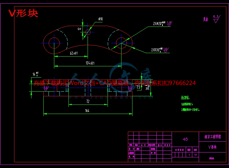
V形块.dwg
上支撑轴套.dwg
下支撑轴套.dwg
中心架上顶盖.dwg
中心架架体.dwg
压板.dwg
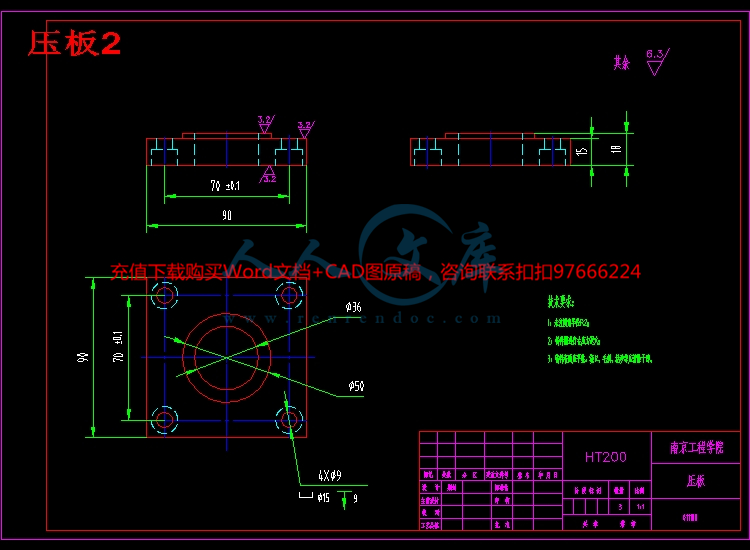
压板2.dwg
支撑圆柱铰链.dwg
支撑轴.dwg
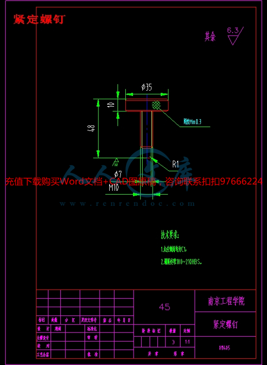
紧定螺钉.dwg
装配图.dwg
调整板.dwg
车床用手动中心架结构设计-开题报告.doc
车床用手动中心架结构设计-英文翻译
设计说明书.doc[15000字,39页]
连接板.dwg
摘要:
本文主要是进行了车床用手动中心架结构的设计 。中心架是车床加工细长轴类零件的辅助功能部件。通过对国内外传统中心架的分析和研究,对现有传统中心架进行了改进设计。该中心架通过调整滚轮径向位置实现不同直径零件的支撑。滚轮与工件直接接触,由传统卡爪对工件的滑动摩擦转变为滚动摩擦,大大延长了卡爪的使用寿命。并利用V形块的自定心原理,对工件实现自动定心。从而大大改善了传统中心架在实际加工过程中效率低,无法自动定心等问题。
关键词:车床 中心架 滚轮 V形块
毕业设计说明书 英文摘要
Title Structure design of manual center frame for lathe
Abstract
This paper mainly carries on the design of the manual center frame structure of the lathe.Center frame is a kind of auxiliary function parts of the lathe to process the slender shaft parts.Through the analysis and research of the traditional center at home and abroad, the existing traditional center frame has been improved.The center frame is realized by adjusting the radial position of the roller wheel to support the support of different diameter parts.The rolling wheel and the workpiece are directly contacted, and the sliding friction of the workpiece is changed into rolling friction by the traditional clamping claws, which greatly prolongs the service life of the clamping claw.And use the self centering principle V block, the workpiece automatic centering.It improves the traditional center frame in the actual process of low efficiency, not self centering etc..
Keywords lathe center frame roller V shape block
目 录
前 言 1
第一章 绪论 2
1.1选题的意义 2
1.1.1车床的发展趋势 2
1.1.2中心架的现实需求 3
1.1.3设计中心架的意义 4
1.2研究内容的背景 4
1.2.1传统中心架在加工过程中遇到的问题 4
1.2.2国内外的研究现状 4
1.3课题的意义 7
第二章 中心架的简介 9
2.1传统中心架的简介 9
2.1.1传统中心架的构造 9
2.1.2传统中心架的工作原理 10
2.1.3传统中心架的使用方法 10
2.1新型中心架的简介 10
2.2.1新型中心架的构造及工作原理 10
2.2.2新型中心架的使用方法 10
2.2.3新型中心架的优缺点 11
第三章 中心架总体结构设计计算 14
3.1压板的锁紧力计算 14
3.2中心架整体拖动力的计算 15
3.3确定中心架支撑直径范围 16
第四章 中心架部件计算 17
4.1滚轮尺寸设计计算 17
4.2支撑滚轮的圆柱铰链尺寸设计 19
4.3轴套尺寸设计计算 20
4.4支撑轴的设计计算 21
4.5中心架架体以及中心架上顶盖总体尺寸设计 22
4.6 V型块总体设计尺寸 24
4.7压板的总体设计尺寸 26
第五章 中心架的计算成本分析 27
5.1 技术经济分析的目的与意义 27
5.2 成本材料分析 27
5.2.1 非标准件 27
5.3 课题技术经济成本计算依据 28
5.3.1成本计算依据 28
第六章 结 论 30
致 谢 32
参考文献 33
附录A 装配图 零件图 34
附录B 毕业论文光盘资料 35


- 内容简介:
-
of of is in of is a as in a In a (is a ) of a by An is to of to of 1,in as by in to be as is an to of to M) as a a of of in VM is to in to ,2an as a of to is a by of or 3 is a 3D of an as of VM of on a To in it is to MC of 1,is a of in as as is as of in is is to is an in in of of of a is as as as be be to as on of a in to M,M,to of of M so be M , to or to M 1,in is of as is a M e.g,) a in a a It In of an a 2, is is a of in of It as as By 1,be A is to of It as to in It of An a to be OM of C AM C in be by C of to ,of a of a to of on is to of of is to as -D 1,of be as a of to a an ID to be by or of of of or A be a a is as T, C, O). of a R a of . in a to:of it is to by in to a R be is at by of of 13/of it is to i, of i). in to (Tt)PT)i of i)is In ID to ID is as ID(v,C,O)1,is Pg A is Sv,v Mn a of in ,Pi C(, of O(to be on of to of to be to a of is to of In to is as a of as 3. of by is a of in It to be to to is to of 1,in A to of in of is by to as as to is as A is of in of A is an is to D
- 温馨提示:
1: 本站所有资源如无特殊说明,都需要本地电脑安装OFFICE2007和PDF阅读器。图纸软件为CAD,CAXA,PROE,UG,SolidWorks等.压缩文件请下载最新的WinRAR软件解压。
2: 本站的文档不包含任何第三方提供的附件图纸等,如果需要附件,请联系上传者。文件的所有权益归上传用户所有。
3.本站RAR压缩包中若带图纸,网页内容里面会有图纸预览,若没有图纸预览就没有图纸。
4. 未经权益所有人同意不得将文件中的内容挪作商业或盈利用途。
5. 人人文库网仅提供信息存储空间,仅对用户上传内容的表现方式做保护处理,对用户上传分享的文档内容本身不做任何修改或编辑,并不能对任何下载内容负责。
6. 下载文件中如有侵权或不适当内容,请与我们联系,我们立即纠正。
7. 本站不保证下载资源的准确性、安全性和完整性, 同时也不承担用户因使用这些下载资源对自己和他人造成任何形式的伤害或损失。

人人文库网所有资源均是用户自行上传分享,仅供网友学习交流,未经上传用户书面授权,请勿作他用。
 川公网安备: 51019002004831号