An analysis of grinding power and surface roughness in exter.pdf
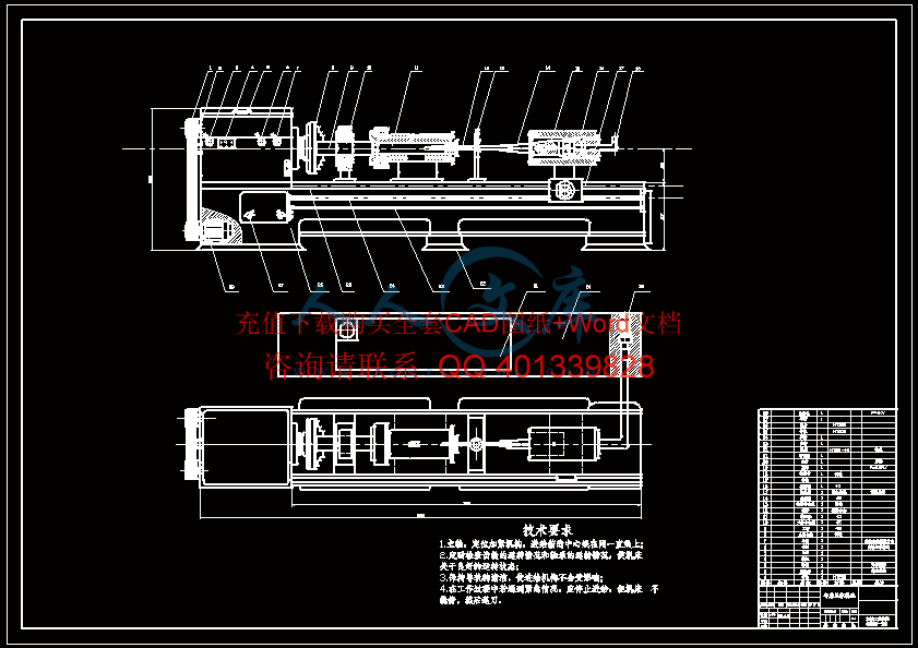
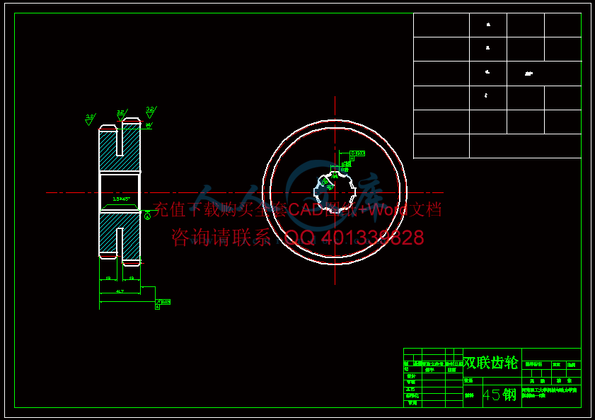
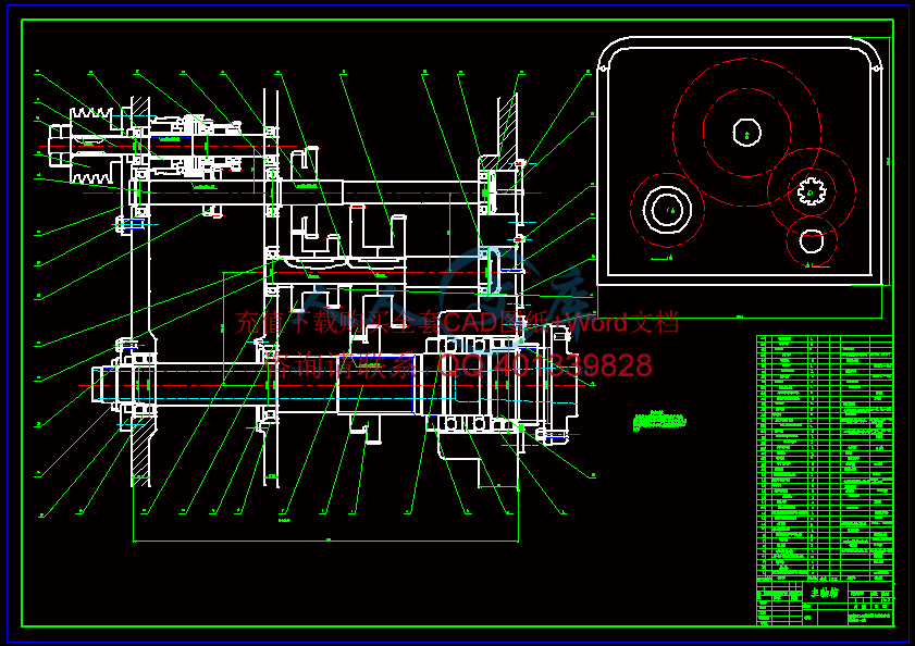
超声波枪钻机床设计【通过答辩毕业论文+CAD图纸】
收藏
资源目录

压缩包内文档预览:
编号:1045180
类型:共享资源
大小:6.41MB
格式:RAR
上传时间:2017-03-05
上传人:机****料
认证信息
个人认证
高**(实名认证)
河南
IP属地:河南
50
积分
- 关 键 词:
-
超声波
钻机
设计
通过
答辩
毕业论文
cad
图纸
- 资源描述:
-


- 内容简介:
-
An analysis of grinding power and surface roughnessin external cylindrical grinding of hardened SCM440 steelusing the response surface methodJae-Seob Kwak*, Sung-Bo Sim, Yeong-Deug JeongSchool of Mechanical Engineering, Pukyong National University, San 100, Yongdang-Dong, Nam-Ku, Busan 608-739, South KoreaReceived 19 January 2005; accepted 19 May 2005Available online 6 July 2005AbstractThe aim of this study was to analyze effectively the grinding power spent during the process and the surface roughness of the groundworkpiece in the external cylindrical grinding of hardened SCM440 steel using the response surface method. A Hall effect sensor was usedfor measuring the grinding power of the spindle driving motor. The surface roughness was also measured and evaluated according to thechange of the grinding conditions. Response surface models were developed to predict the grinding power and the surface roughness usingthe experimental results. From adding simply material removal rate to the contour plot of these mathematical models, it was seen that usefulgrinding conditions for industrial application could be easily determined.q 2005 Elsevier Ltd. All rights reserved.Keywords: Grinding power; Surface roughness; External cylindrical grinding; Response surface method1. IntroductionA lot of attempts have been made to describe moreeffectively and adequately the grinding process. This isdissimilar to other machining processes such as turning andmilling, as the cutting edges of the grinding wheel dont haveuniformity and act differently on the workpiece at eachgrinding. In spite of these attempts, typified by 13,describing the grinding action between the grinding wheeland the workpiece has not been made clear. So statisticalmodels 4 and computer simulations 5 that could deal withthe variety of the cutting edges were introduced. Thesecomplexities and difficulties of illustrating the grindingprocessalsoraiseobstaclestotheoptimizationofthegrindingprocessandtotheverificationoftheinterrelationshipbetweengrinding parameters and outcomes of the process 67.Malkin 89 investigated the process monitoring andstudied various grinding phenomena such as cuttingmechanisms, the specific energy and the interrelationshipof the parameters during past decades. In his research, it wasseen that the grinding process had very complex cuttingmechanisms and also repeatability was difficult to obtainunder the same grinding conditions. Shaji 10 reported astudy on the Taguchi method for evaluating processparameters in surface grinding with graphite as lubricant.The effect of the grinding parameters (wheel speed, tablespeed, depth of cut and the dressing mode) on the surfacefinish and the grinding force was analyzed. Kwak 11showed that the various grinding parameters affected thegeometric error generated during the surface grinding byusing theTaguchi method and also the geometricerror couldbe predicted by means of the response surface method.In this study, the response surface models are developedto predict the grinding power and the surface roughness inthe external cylindrical grinding of the hardened SCM440steel and also to help the selection of grinding conditions.2. Literature review2.1. Chip geometry of external cylindrical grindingThe cutting mechanism of the grinding process is verycomplex and not clear because the grinding wheel has manyInternational Journal of Machine Tools & Manufacture 46 (2006) 304312/locate/ijmactool0890-6955/$ - see front matter q 2005 Elsevier Ltd. All rights reserved.doi:10.1016/j.ijmachtools.2005.05.019*Tel.: C82 51 620 1622; fax: C82 51 620 1531.E-mail address: jskwak5pknu.ac.kr (J.-S. Kwak).irregular abrasives that are randomly distributed in theworking area of the wheel circumference. Under severalassumptions for convenience, the enlarged contact geome-try in the external cylindrical grindingprocess can be simplyillustrated as shown in Fig. 1.From the chip geometry, it is seen that a cutting edge onthe circumference of the grinding wheel contacts firstly apoint C on the workpiece and then it moves along the arcCD (contact length) during the grinding. So the chipthickness in a viewpoint of the cutting edge increasesgradually from C to I and peaks at point I. And then, the chipthickness decreases from I to D. The maximum chipthickness (g) in the cutting edge is about equal to the lengthHI and can be expressed as below.g ZHI ZDH sinaCb Z2avVffiffiffiZpffiffiffiffiffiffiffiffiffiffiffiffiffidCDdDr(1)Where d and D represent the workpiece diameter and thewheel diameter, respectively. Z is the depth of cut. Themaximum chip thickness is mostly affected by an averagedistance (a) between the successive cutting edges atthe grinding wheel and the speed ratio (vV). The arc of thecontact length (lc) between the grinding wheel and theworkpiece can also be represented by applying a small angleapproximation.lcZ2ffiffiffiZpffiffiffiffiffiffiffiffiffiffiffiffiffidDdCDr1CvV?(2)Considering traverse speed f that is a traverse length perrevolution in the workpiece, a tangential grinding force Ftand an energy Pospent during grinding are as follows.FtZlcZ2vVf;P0ZFtV(3)From Eq. (3), it is seen that the tangential grinding force(or energy) in the external cylindrical grinding directlyconcerns a selection of the grinding parameters.2.2. Hall effect and grinding power measurementUsually to measure the spent power of a machine duringthe process, the Hall effect sensor would be available inmany types of industrial applications. The principle of theHall effect sensor is based on the Hall effect, which wasdiscovered by Dr Edwin Hall in 1879.The current flowing through a cable from the drivingmotor of a grinding machine produces a magnetic field. Ifthe cable passes into the Hall effect sensor, an inducedvoltage in the sensor is developed due to the Lorentz force.This voltage is known as the Hall voltage and the amount ofthe Hall voltage is proportional to the original currentflowing into the cable. So from measuring the changes of theHall voltage, the spent power of the driving motor can beeasily obtained during the grinding process.2.3. Response surface methodThe response surface analysis is one of various methodsfor optimizing and evaluating the process parameters toachieve the desired output. In this method, the desiredoutput can be represented as a function of the processparameters. The function that consists of the processparameters is called a response surface as shown in Fig. 2.In order to develop the response surface model, firstly thefunction must be assumed as a mathematical polynomialform having coefficients that should be determined. Andthen these coefficients are determined with applying the setof the experimental results.In the case of the situation that the response surfacefunction is related to various process parameters and a lot ofexperiments are conducted, the calculation for determiningcoefficients of the polynomial equation is very complex.And also it is difficult to finish the calculation bydetermining adequate coefficients that have to satisfy allWheelWorkpieceAB+FHCIvVaRrDZFig. 1. Illustration of grinding depth and contact length.Temperature, 1Time, 2Response, y231yyResponse surfaceContour lineFig. 2. Describing the concept of a response surface model.J.-S. Kwak et al. / International Journal of Machine Tools & Manufacture 46 (2006) 304312305of the experimental results. The scheme of a least squareerror, therefore, is usually adopted and a commercial code isused for convenience of the multiple calculation.3. Grinding experiment and obtained results3.1. Experimental set-upThe experimental set-up for the external cylindricalgrindingused in this study is shown in Fig. 3.The workpiecematerial was the chromiummolybdenum steel (SCM440)and heat-treated to Rc60. This material is commonly usedfor rotating shafts. The grinding wheel was a type ofWA120 Km V that is widely used in various industrialareas. The diameter of the wheel was 320 mm and the width38 mm.To evaluate the change of the grinding energy accordingto the various grinding conditions, three Hall effect sensorswere installed in the electric cables of the grinding spindlemotor. The current source of 12 V in the Hall effect sensorswas supplied from a DC power supply unit. The sensitivitybetween the current change in the spindle motor andthe output voltage in the Hall effect sensor was 0.4 V/A. Theresponse time of the sensor was about 0.5 ms. The outputvoltage of the sensor was continuously measured by usingan A/D converter and an oscilloscope during the grindingprocess. After the grinding, the surface roughness in thetraverse direction in the workpiece was measured.Hall sensorPower supplyWorkpieceCoolantGrinding wheelA/D converter+12V 0V12VP.COscilloscopeGrinding motorFig. 3. Schematic drawing of used experimental set-up.010000200003000040000700800900100011001200DCBAGrinding power (W)Number of dataFig. 4. Typical signal form of measured grinding power using Hall effectsensor.1520253035408001000120014001600 f=1.19m/min f=1.46m/min f=2.14m/min f=1.19m/min f=1.46m/min f=2.14m/min f=1.19m/min f=1.46m/min f=2.14m/minGrinding power (W)Depth of cut (m)Depth of cut (m)Depth of cut (m)(a) Workpiece speed : 52rpm15202530354080010001200140016001800Grinding power (W)(b) Workpiece speed : 64rpm152025303540800100012001400160018002000Grinding power (W)(c) Workpiece speed : 76rpmFig. 5. Effect of depth of cut on grinding power.J.-S. Kwak et al. / International Journal of Machine Tools & Manufacture 46 (2006) 304312306In the grinding conditions, the workpiece revolutionspeeds were 52, 64 and 76 rpm. The depths of cut in a passwere 20, 25, 30 and 35 mm and the traverse speeds were 1.19, 1.46 and 2.14 m/min. The wheel speed (1800 rpm) wasmaintained and a water-miscible coolant was supplied in allgrinding experiments.3.2. Effect of grinding conditions on powerThe grinding power that was spent during the grindingprocess was obtained by multiplying the measured currentflowing into the spindle motor cable and the suppliedvoltage of the motor. Fig. 4 shows a typical signal form ofthe grinding power during the process cycle that consistedof 4 individual parts illustrated as A, B, C and D. Region Awas an idle stage with no contact between the grindingwheel and the workpiece. Although there was no contact,power was used in turning the grinding wheel. On contactbetween the wheel and the workpiece, the grinding power(see region B shown in Fig. 4) changed. The amount ofchange depended on the grinding conditions. For conven-ience, in this study, the total grinding power, which addedthe driving power to the net grinding power, was defined as1520253035400134567Surface roughness (m)Depth of cut (m) v = 52 rpm (Rmax) v = 64 rpm (Rmax) v = 76 rpm (Rmax) v = 52 rpm (Ra) v = 64 rpm (Ra) v = 76 rpm (Ra)(a) Traverse speed :1.46m/min1520253035400.60.70.80.9Surface roughness Ra (m)Depth of cut (m) f = 1.19m/min f = 1.46m/min f = 2.14m/min(b) Workpiece speed : 64rpmFig. 7. Effect of depth of cut on surface roughness.506070808009001000110012001300Grinding power (W)Workpiece speed (rpm)d = 20 md = 25 md = 30 md = 35 md = 20 md = 25 md = 30 md = 35 md = 20 md = 25 md = 30 md = 35 m(a) Traverse speed : 1.19m/min50607080900100011001200130014001500Grinding power (W)Workpiece speed (rpm)(b) Traverse speed: 1.46m/min5060708010001200140016001800Grinding power (W)Workpiece speed (rpm)(c) Traverse speed: 2.14m/minFig. 6. Effect of workpiece speed on grinding power.J.-S. Kwak et al. / International Journal of Machine Tools & Manufacture 46 (2006) 304312307the grinding power spent during the external cylindricalgrinding process. At the end of a feed forward action in thegrinding wheel, the grinding wheel started the feedbackward traverse, referred to spark-out motion shown inregion C. As seen in region C, the grinding power was lessthan that of the feed forward traverse but was more than thedriving power. Finally in region D, the grinding wheeldisengaged the workpiece and finished the process cycle.Fig. 5 presents the effect of the depth of cut on thegrinding power for different workpiece revolution speed andtraverse speed. The grinding power spent during thegrinding process increased with increasing depth of cut(Fig. 6). Although the slopes of the grinding power increaseswere somewhat different, grinding power was also increasedwith increasing workpiece speed and traverse speed. Theeffect of the workpiece speed on grinding power is shown inFig. 7. Although the same workpiece speed was applied, thegrinding power differed about 1.6 times according tothe depth of cut. From the results, it is seen that increasingthe depth of cut affected the grinding power more thanincreasing the traverse speed.3.3. Effect of grinding conditions on surface roughnessFig. 7 shows the effect of depth of cut on surfaceroughness of the workpiece, which is measured along thetraverse direction. Fig. 7 (a) shows surface roughness fordifferent depths of cut and workpiece speeds. According tothe change of the depth of cut, the maximum height (Rmax)of the surface roughness increased proportionally but thecenterline average height (Ra) changed little especially inthe case of the traverse speed of 1.46 m/min. Fig. 7 (b)shows the centerline average height of the surface roughnessfor different depths of cut and traverse speeds.3.4. Effect of spark-out on grinding power and surfaceroughnessTo determine how spark-out motion affected the grindingpower and the surface roughness, the experiments wereconducted. The effect of the spark-out on the grinding powerand the surface roughness are presented in Fig. 8.900120015001800900120015001800Measured grinding power (W)Predicted grinding power (W)(a) Grinding power0.80.90.50.60.70.80.9Measured surface roughness (m)Predicted surface roughness (m)(b) Surface roughnessFig. 9. Comparison between measured value and predicted value byapplying developed response surface model.152025303540800100012001400160018002000Grinding power (W)Depth of cut (m) f = 1.19 m/min, 1st f = 2.14 m/min, 1st f = 1.19 m/min, 6th f = 2.14 m/min, 6th1520253035400.40.50.60.70.80.9Surface roughness Ra (m)Depth of cut (m) f = 1.19m/min, 1st f = 2.14m/min, 1st f = 1.19m/min, 6th f = 2.14m/min, 6th(b) Surface roughness(a) Grinding powerFig. 8. Effect of spark-out on grinding power and surface roughness.J.-S. Kwak et al. / International Journal of Machine Tools & Manufacture 46 (2006) 304312308In the case of the first spark-out implementation, thegrinding power maintained a higher magnitude according tothe depth of cut as shown in Fig. 8 (a). But in the case of the6th spark-out implementation, the grinding power wentdown to near the driving power of the spindle motor at theidle stage and wasnt affected by the depth of cut or thetraverse speed. In this stage, there is no more materialremoval. So, it was seen that material removal in externalcylindrical grinding was completed after several spark-outs.The centerline average height of the surface roughness isshown in Fig. 8 (b). After the 6th spark-out implementation,the surface roughness according to the depth of cut had notconverged to a constant magnitude and a desired surfaceroughness in certain cases was not achieved even by severalspark-outs. This is a dilemma to be solved, because morespark-outs decrease production rate but produce a goodsurface roughness. Therefore it is necessary to deal with thismatter carefully, especially in the selection of the grindingconditions.4. Applying response surface method4.1. Development of response surface modelsAs mentioned in the previous section of this study, it isdesirable to be able to forecast grinding power and surfaceroughness according to the grinding conditions. One meansof doing this is to represent grinding outcomes mathemat-ically as a function of the applicable grinding parameters. Inthis study, the response surface method was used to achievethe aim. Second-order response surface models using theworkpiece revolution speed v (rpm), the traverse speed f(m/min) and the depth of cut d (mm) were developed asFig. 10. Response surface and contour plot of grinding power according to change of workpiece speed and traverse speed.J.-S. Kwak et al. / International Journal of Machine Tools & Manufacture 46 (2006) 304312309below.PoZ359:83797K0:10070v2K184:65033f2K0:65000d2C3:95418vf C0:45254vdC24:94593fd(4)RaZ0:21369K0:00009v2K0:09995f2C0:00051d2C0:01156vf C0:00002vdK0:00979fd(5)Where, the symbol Po(W) was the grinding power and Ra(mm) the surface roughness. Fig. 9 shows the differencebetween the measured quantity and the predicted quantityby applying the developed response surface models lists inEqs. (4) and (5). As shown in Fig. 9(a), the predictedgrinding power well coincides with the measured grindingpower and also the predicted surface roughness shown inFig. 9(b) corresponded with the measured value although ithad some wide deviation in the distribution.Fig. 10 presents an example of the response surface andcontour plots of the grinding power according to the changeof the workpiece speed and the traverse speed. In theseplots, the depth of cut was fixed as 25 mm. The 3D plot ofFig. 11. Response surface and contour plot of surface roughness according to change of workpiece speed and traverse speed.J.-S. Kwak et al. / International Journal of Machine Tools & Manufacture 46 (2006) 304312310the grinding power shown in Fig. 10 (a) seems to increaselinearly in accordance with increasing the workpiece speedand the traverse speed. But from the contour plot shown inFig. 10 (b), it is seen that the traverse speed has a greaterinfluence on the grinding power. A small change of thetraverse speed with a fixed workpiece speed, affected thegrinding power.The 3D plot of the surface roughness, as represented inFig. 11, shows a more rapid change than the grinding poweraccording to the workpiece speed and the traverse speed.The surface roughness was dominantly affected by thechange of the workpiece speed.4.2. Validation of developed response surface modelsIn past decades, selecting the grinding conditionsstrongly depended upon an experts judgment. So, it wasvery difficult for beginners or unskilled workers todetermine the proper grinding conditions to satisfy alldemanded constraints such as the surface roughness, thematerial removal rate and the grinding power to be spent.The developed response surface models enable selection ofthe grinding conditions without much grinding experience.The material removal rate per minute, MRR (mm3/min),during the external cylindrical grinding can be written asfollows:MRRmm3=min Zd ? f ? Da(6)In Eq. (6), the symbol Da(mm) represents the averagediameter of the used workpiece. If three constraints forindustrial application were as Eqs. (7)(9), the selectedgrinding conditions have to satisfy all constraints. Althoughit looks like a conventional optimization problem, it can besimply solved by using the developed response surfacemodels.0:70%Ramm?%0:85(7)4000%MRR mm3=min?%7000(8)1000%PoW%1500(9)An example is presented in Fig. 12. In this case, theworkpiece revolution speed was fixed as 64 rpm. Firstly thecontour plot of the surface roughness was drawn accordingto the change of the traverse speed and the depth of cut andthen the given constraint ranges at the material removal rateand the grinding power were added into the contour plot.Now, the grinding conditions satisfying all constraints canbe determined by selecting an inside region enclosed by theconstraints lines.5. Concluding remarksIn this study, the response surface method was appliedfor analyzing the grinding power and the surface roughnessin the external cylindrical grinding of the hardened SCM440material. A Hall effect sensor was used to measure thegrinding power of the spindle driving motor during thegrinding.Based on experimental results, increasing the depth ofcut affected the grinding power more than increasingFig. 12. Contour plot of surface roughness with constraints of material removal rate and grinding power for selecting permissible range of grinding conditions.J.-S. Kwak et al. / International Journal of Machine Tools & Manufacture 46 (2006) 304312311the traverse speed. In addition, increasing the depth of cutchanged the maximum height of the surface roughness morethan the centerline average height. After several spark-outs,the grinding power went down to near the driving powerbut, in certain cases, the desired surface roughness was notobtained.By using the grinding parameters, the second-orderresponse surface models for the grinding power and thesurface roughness in the external cylindrical grinding weredeveloped. Therefore, it is possible to predict the grindingpower and the surfac
- 温馨提示:
1: 本站所有资源如无特殊说明,都需要本地电脑安装OFFICE2007和PDF阅读器。图纸软件为CAD,CAXA,PROE,UG,SolidWorks等.压缩文件请下载最新的WinRAR软件解压。
2: 本站的文档不包含任何第三方提供的附件图纸等,如果需要附件,请联系上传者。文件的所有权益归上传用户所有。
3.本站RAR压缩包中若带图纸,网页内容里面会有图纸预览,若没有图纸预览就没有图纸。
4. 未经权益所有人同意不得将文件中的内容挪作商业或盈利用途。
5. 人人文库网仅提供信息存储空间,仅对用户上传内容的表现方式做保护处理,对用户上传分享的文档内容本身不做任何修改或编辑,并不能对任何下载内容负责。
6. 下载文件中如有侵权或不适当内容,请与我们联系,我们立即纠正。
7. 本站不保证下载资源的准确性、安全性和完整性, 同时也不承担用户因使用这些下载资源对自己和他人造成任何形式的伤害或损失。

人人文库网所有资源均是用户自行上传分享,仅供网友学习交流,未经上传用户书面授权,请勿作他用。
|
2:不支持迅雷下载,请使用浏览器下载
3:不支持QQ浏览器下载,请用其他浏览器
4:下载后的文档和图纸-无水印
5:文档经过压缩,下载后原文更清晰
|
 川公网安备: 51019002004831号