英文.doc

焊接机械手的结构设计【9张CAD图纸和说明书】

收藏

资源目录
跳过导航链接。
焊接机械手的结构设计【9张CAD图纸和说明书】.rar
英文.doc---(点击预览)
毕业论文.doc---(点击预览)
开题报告 焊接机械手的结构设计.doc---(点击预览)
外文文献.pdf---(点击预览)
中期报告.doc---(点击预览)
中文.doc---(点击预览)
A3 40减速器.dwg
A3 80减速器.dwg
A3-40减速机支撑座.DWG
大臂壳体整体a2.DWG
套轴a3.DWG
整体装配图a0.DWG
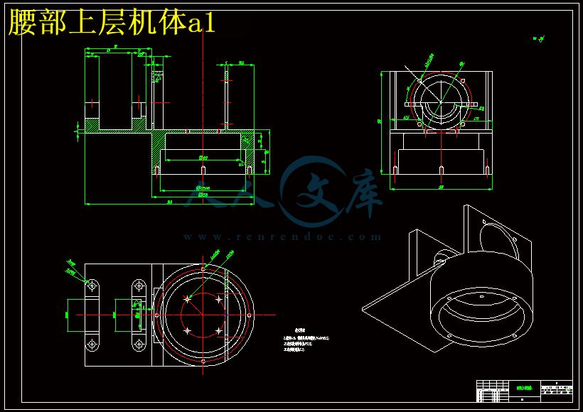
腰部上层机体a1.DWG
腰部壳体a1.DWG
长杆a3.DWG
压缩包内文档预览:
预览图 预览图 预览图 预览图 预览图 预览图 预览图 预览图
编号:19057793    类型:共享资源    大小:1.93MB    格式:RAR    上传时间:2019-05-08 上传人:俊****计 IP属地:江苏
40
积分
关 键 词:
9张CAD图纸和说明书 焊接机械手的结构设计【 9张cad图纸和 焊接 机械手 cad 图纸 焊接机械手结构的设计【 CAD图纸】 结构的设计【 焊接机械手的结构设计 张CAD图纸 张CAD图纸】
资源描述:

摘  要

本设计为焊接机械手的结构设计,主要研究内容:腰部回转机构的设计;大、小臂和腕部回转的结构设计。

本设计由整体布局入手,参考现有关节型机械臂的相关设计,初步确定腰部的转动惯量,从而确定电机的选型,安装等相关设计。在机械臂的灵活和精度的前提下完成总体结构的设计,然后根据总体结构,从而确定本设计的机械臂各个主要零部件的设计。

在主要零部件的设计中,主要包括腰部壳体的设计、轴的结构设计、轴承的选择、电机的设计计算、大小臂的结构和固定等。

本设计整体在现有关节型机械臂的结构上做了修改,使得它能够更好的满足本设计的设计要求。本设计结构简单、重量轻、外形尺寸小、设备费用低、运转安全、操作方便、便于维修和管理。


关键词:机械手;谐波减速器;结构设计


Structure design of robot arm

Abstract

The design for the design of welding structure of the manipulator, the main research contents: the design of the waist turning mechanism; structure design of large, small arm and wrist rotation.

This design by the overall layout with reference to the relevant design, the existing joint type manipulator, preliminary determine the moment of inertia of the waist, so as to determine the motor selection, installation and other related design. Complete the design of the overall structure of the flexible manipulator based on precision and the next, and then based on the overall structure, design of mechanical arm to determine the design of all the major components of the.

The design of the main components, including the housing design, structural design of shaft, bearing selection, design and calculation of the size of motor, arm structure and fixed.

The design of the whole made changes in the existing joint type manipulator structure, so that it can better meet the design requirement of this design. The design has simple structure, light weight, small size, low cost of equipment, operation safety, convenient operation, easy to repair and management.


KeyWords:robot arm;harmonic drive;structure design

目  录

1 绪论 1

1.1 机器人简介 1

1.1.1  机器人的发展及应用 2

1.1.2  点焊机器人介绍及其研究意义 4

1.1.3  机器人的组成 6

1.2 机械手的组成 8

1.3 本文主要研究工作 11

2  机械手的总体结构 12

2.1 机械手总体结构的类型 12

2.2 设计具体采用方案 13

3  机械手腰部机座 15

3.1 机械手腰部机座结构的设计 15

3.2 机械手腰部机座设计的具体采用方案 15

3.3 电动机的选择 16

3.4 减速器的选择 17

3.5 键的选择 18

4  机械手手臂的结构设计 20

4.1 设计具体采用方案 21

4.2 大臂电动机的选择 21

4.3 大臂减速器的相关计算 22

4.4 小臂电动机的选择 23

4.5 小臂减速器的相关计算 24

5  机械手腕部的结构方案设计 27

5.1 腕部电动机的选择 27

5.2 腕部减速器的选择 27

6  轴承的选用与校核 29

7  结论 39

参考文献 40

致谢 41

毕业设计(论文)知识产权声明 42

毕业设计(论文)独创性声明 43


1 绪论

1.1 机器人简介

工业机器人(英语:industrial robot。简称IR)是广泛适用的能够自主动作,且多轴联动的机械设备。它们在必要情况下配备有传感器,其动作步骤包括灵活的,转动都是可编程控制的(即在工作过程中,无需任何外力的干预)。它们通常配备有机械手、刀具或其他可装配的的加工工具,以及能够执行搬运操作与加工制造的任务。机器人是靠自身动力和控制能力来实现各种功能的一种机器。联合国标准化组织采纳了美国机器人协会给机器人下的定义:“一种可编程和多功能的,用来搬运材料、零件、工具的操作机;或是为了执行不同的任务而具有可改变和可编程动作的专门系统[1]。”

工业机器人在经历了长期发展后,已经成为制造业中不可缺少的核心设备。同时随着社会的发展和人们生活水平的提高,各种各样的机器人也被开发出来去适应制造领域意外的各个行业。这些机器人作为机器人家族的后起之秀,由于其用途广泛而大有后来居上之势,仿形机器人、农业机器人、服务机器人、水下机器人、医疗机器人、军用机器人、娱乐机器人等各种用途的特种机器人纷纷面世,而且正以飞快的速度向实用化迈进。

工业机器人由操作机(机械本体)、控制器、伺服驱动系统和检测传感装置构成,是一种仿人操作、自动控制、可重复编程、能在三维空间完成各种作业的机电一体化自动化生产设备。特别适合于多品种、变批量的柔性生产。它对稳定、提高产品质量,提高生产效率,改善劳动条件和产品的快速更新换代起着十分重要的作用。 

机器人并不是在简单意义上代替人工的劳动,而是综合了人的特长和机器特长的一种拟人的电子机械装置,既有人对环境状态的快速反应和分析判断能力,又有机器可长时间持续工作、精确度高、抗恶劣环境的能力,从某种意义上说它也是机器的进化过程产物,它是工业以及非产业界的重要生产和服务性设备,也是先进制造技术领域不可缺少的自动化设备。


1.1.1 机器人的发展及应用

1920年 捷克斯洛伐克作家卡雷尔·恰佩克在他的科幻小说《罗萨姆的机器人万能公司》中,根据Robota(捷克文,原意为“劳役、苦工”)和Robotnik(波兰文,原意为“工人”),创造出“机器人”这个词。

1939年 美国纽约世博会上展出了西屋电气公司制造的家用机器人Elektro。它由电缆控制,可以行走,会说77个字,甚至可以抽烟,不过离真正干家务活还差得远。但它让人们对家用机器人的憧憬变得更加具体。

1942年 美国科幻巨匠阿西莫夫提出“机器人三定律”。虽然这只是科幻小说里的创造,但后来成为学术界默认的研发原则。

1954年 美国人乔治·德沃尔制造出世界上第一台可编程的机器人,并注册了专利。这种机械手能按照不同的程序从事不同的工作,因此具有通用性和灵活性。


内容简介:
ABSTRACTA robot arm comprises a first and a second link, the first link having a proximal end and a distal end and the second link having a proximal and a distal end. A fixed pulley, with circumferential surfaces concentric with the first pivot axis is mounted at the proximal end of the first link. A second-link pulley is fixed to the second link for rotation about the second pivot axis. An end effector pulley is fixed to the end effector for rotation about the third pivot axis. A first belt drive is also provided and includes one or more belts connected between the circumferential surfaces of the fixed pulley and the second link pulley so that ratation of the first link relative to the fixed pulley about the first pivot axis causes rotation of the second link about the second pivot axis relative to the first link. One or more idler pulleys is provided and is rotatably mounted to one or both of the links.At least one of the belt drives includes a first belt engaged with the first circumferential surface of an idler pulley and a second belt engaged with the second circumferential surface of the same idler pulley.16 Claims, 3 Drawing Sheets 1ROBOT ARM CROSS REFERENCE TO RELATED APPLICATION This application claims the benefit of U.S. Provisional patent application No. 60/122,184 filed on Mar. 1, 1999, the disclosure of which is incorporated by reference. FIELD OF THE INVENTION The present invention relates to a robot arm having an end effector located at the remote end of the robot arm maintaming the same orientation regardless of rotational movemenu of the arm. The robot arm also has at least one idler pulley located within one of the links that allow the diameter of the joints to be enlarged so that wires or other elongated components may pass through the interior of the joints. BACKGROUND OF THE INVENTION In the semiconductor industry, robot arms have typically been employed to move semiconductor wafers from one location to another. It is desired in the design of a robot arm in the semiconductor industry to have the end effector maintain the same orientation when the arm moves radially inward and outward. As discussed, for example, in U.S. Pat.Nos. 4,299,533 and 5,064,340, robot arms have been provided with two links and an end effector mounted at a distal end of the second link. The proximal end of the first link is mounted coaxially with a pulley, referred to herein as the fixed pulley. The proximal end of the second link is pivotally connected to the distal end of the first link. A first belt connects the fixed pulley to a second link pulley at theproximal end of the second-link, whereas a second belt connects a housing fixed to the distal end of the first link to a pulley on the end effector. If the lengths of the links are equal, and if the pulleys are selected so that the ratio of rotation of the end effective to rotation of the second link is一关and the ratio of rotation of the second link to rotation of the first link is -2, the end effector will remaining fixed orientation but will move radially when the first link rotatesrelative to the fixed pulley. While this approach is effective, it imposes some serious design constraints. To provide the desired ratios, a relatively large end effector pulley is needed. For the end effector to rotate one-half the rotation of the second link, the pulley at the end effector must be twice as large as the housing on the distal end of the first link. When the pulley at the end effector is large, it adds significant mass to the end of the robot arm, increasing inertia and making it much more difficult to control precisely the movements of the arm. Also, to provide the desired ratios, the second link pulley and the housing at the distal end of the second link must be of relatively small diameter, i.e., half the diameter of the fixed pulley. This makes it difficult to connect to wires,pneumatic tubes, or other elongated components extending from the first to the second neighboring link through a hollow bore at the exit of the second link pulley and housing.Such wires, tubes and other elongated components are usually part of the control system for controlling the end effector. Thus, it would be desired to create a robot arm withenough space at the joint between the links so that these wires and tubes can pass through the center of the joint. The robot arm of the present invention addresses the problems set forth above and is described more fully below. SUMMARY OF THE INVENTION In accordance with one embodiment of the present invention, a robot arm comprises a first and a second link,the first link having a proximal end and a distal end and the second link having a proximal and a distal end. The proximal end of the first link is pivotally connected to a base for rotation relative to a first pivot axis. The proximal end of the second link is pivotally mounted to the distal end of the first link and is capable of rotation about a second pivot axis that is parallel to the first pivot axis. An end effector is pivotally connected to the distal end of the second link and is capable of rotation about a third pivot axis which is parallel to the first and second pivot axes. A fixed pulley, with a circumferential surface concentric with the first pivot axis is mounted at the proximal end of the first link. A second-link pulley is fixed to the second link for rotation with the second link about the second pivot axis. The second link pulley has a circumferential surface concentric with the second pivot axis. A housing is provided and is fixed to the first link at its distal end. The housing has a circumferential surface concentric with the second pivot axis. An end effector pulley is fixed to the end effector for rotation about the third pivot axis and the end effector pulley has circumferential surfaces concentric with the third pivot axis. A first belt drive is also provided and includes one or more belts connected between the circumferential surface of the fixed pulley and the circumferential surface of the second-link pulley so that rotation of the first link relative to the fixed pulley about the first pivot axis causes rotation of the second link about the second pivot axis relative to the first link. The first belt drive is arranged to provide a first ratio between the rotation of the first link relative to the fixed pulley and rotation of the second link relative to the fixed pulley. A second belt drive includes one or more belts connected between the circumferential surface of the housing and the circumferential surface of the end effector pulley so that rotation of the second link relative to the first link, about the second pivotaxis, causes rotation of the end effector about the third pivot axis relative to the second link. The second belt drive is arranged to provide a second ratio between the rotation of the second link relative to the first link and rotation of the end effector relative to the second link. One or more idler pulleys are provided and are rotatably mounted to one or both of the links. Each of the idler pulleys define a first and second circumferential surface. At least one of the belt drives includes a first belt engaged with the first circumferential surface of an idler pulley and a second belt engaged with the second circumferential surface of the same idler pulley. Preferably, the first ratio has a value of -2 where rotation of the first link through an angle 8 causes the second link pulley and the second link to turn through an angle of -26 with respect to the first link. Thus, if the first link travels through a 450 angle counterclockwise, this will result in the second link pulley and the second link turning through an angle of 900 in the clockwise direction relative to the first link. It is also preferred that the second ratio has a value of ? where rotation of the second link through an angle 0 causes the end effector pulley and the end effector to turn through an angle of -1/z0 with respect to the second link. For example, if the second link turns through an angle of 90degrees in the clockwise direction, this will result in the end effector pulley and the end effector turning through an angle of 450 in the counterclockwise direction relative to the second link. Because one or more of the belt drives includes an idler pulley and two belts, the pulley and housing diameters need not be selected as described above in connection with the prior art belt drives. For example, where the robot arm includes a first idler pulley mounted to the first link, the first belt of the first belt drive engages the first circumferential surface of the idler pulley and the circumferential surface of the fixed pulley. The second belt of the first belt drive engages the second circumferential surface of the first idler pulley and the circumferential surface of the second-link pulley. Also preferably, the robot arm has a second idler pulley mounted to the second link. The second belt drive desirably comprises a first belt extending from the circumferential s surface of the housing to the first circumferential surface of the second idler pulley. The second belt drive desirably further comprises a second belt extending from the second circumferential surface of the second idler pulley to the end effector pulley. Preferably, the ratio of the diameter of the first circumferential surface of the second idler pulley to the diameter of the second circumferential surface of the second idler pulley is more than 1:1 as, for example 2:1. This ratio of more than 1:1 in the second idler pulley allows a relatively smaller end effector pulley on a smaller housing, or both, than what will be provided in the absence of the second idler pulley. Preferably, the robot arm further includes elongated components and the second link pulley and housing include an internal bore. The elongated components desirably extend from the first link through the bore and into the second link.These elongated components may include wires, fiber optics or pneumatic or hydraulic hoses that are needed to operate the robot arm. The end effector pulley may also include an internal bore, and the elongated components can extend from the second link to the end effector. Preferably, the robot arm further includes a base and a first rotary motion actuator that is connected to the base of rotation for rotating the first link relative to the fixed pulley about the first pivot axis so as to move the end effector radially as described above. A further rotary motion actuator may be provided for rotating the fixed pulley and the first link so as to swing the entire arm about the first pivot axis.BRIEF DESCRIPTION OF THE DRAWINGS FIG. 1 is a perspective view of a robot arm in accordance with one embodiment of the present invention. FIG. 2 is a cross-sectional elevational view of the robot arm in FIG. 1. FIG. 3 is a top cross-sectional view of the robot arm ofFIG. 1 with the first link partially shown in phantom.DE7AILED DESCRIPTION OF THE PREFERRED EMBODIMENT As shown in FIGS. 1一,a robot arm 10 is mounted to a base 11 and has a first link 12 and a second link 14. The first link has a proximal end 16 and a distal end 18. Likewise, the second link 14 has a proximal end 20 and a distal end 22. The first and second links 12 and 14 are preferably hollow and can be made of metal, plastic or any other suitable material. First link 12 is mounted to base 12 for rotation relative to the base about a first pivot axis 28 of a first joint 24 at the proximal end 16 of the first link 12. A fixed pulley 26 is also mounted for rotation about the first pivot axis 28 at the first joint 24. The fixed pulley 26 includes a circumferential surface 30 (FIG. 3) that is concentric with the first pivot axis 28. Also extending from the first joint 24 is a shaft 32 fixed to the first pulley and a drive pulley 33 fixed to first link 12. Drive pulley 33 is connected to a first rotary motion actuator 35 so that the first actuator can drive the first link in rotation about axis 28. Shaft 32 is connected to a second actuator 37 which can drive the fixed pulley 24 in rotation about the axis 28 concurrently with rotation of the first link 12 or hold the drive pulley fixed against such rotation. The first actuator may include any conventional rotary actuator such as, for example, a stepped motor, a conventional electric motor, or the like. The second actuator may include similar components, or may include a first brake to link the fixed pulley 24 to arm 12 for rotation therewith and a second brake to hold the fixed pulley in a fixed position relative to the housing. The first and second actuators are commanded by a conventional control system (not shown). The first link 12 and the second link 14 are pivotally connected at a second joint 34. The first and second links 12 and 14 are able to rotate with respect to each other about a second pivot axis 36 that is parallel to the first pivot axis 28. A second-link pulley 38 is mounted on the second joint 34 and has a circumferential surface 40 that is concentric with the second pivot axis 36. The second-link pulley 38 is fixed to the second link 14. A housing 42 is also provided at the second joint 34 and is fixed to the first link 12. The housing 42 also has a circumferential surface 44 that is concentric with the second pivot axis 36. A third joint 46 is provided at the distal end 22 of the second link 14. An end effector pulley 48 is mounted at the third joint 46 and is able to rotate about a third pivot axis 50. The end effector pulley 48 has a circumferential surface 52 concentric with the third pivot axis 50. An end effector 54 is attached to the end effector pulley 48 and is capable of rotation about the third pivot axis 50. The end effector 54 may include fingers or other fixtures for holding a workpiece to be moved. A first idler pulley 56 is mounted to the first link 12 between the fixed pulley 26 and second-link pulley 38. The first idler pulley 56 has a first circumferential surface 58 and a second circumferential surface 60. A second idler pulley 62 is mounted to the second link 14 and has a first circumferential surface 64 and a second circumferential surface 66. The first and second idler pulleys 56 and 62 rotate about axes 68 and 69 that are parallel to the first, second and third pivotaxes 28, 36 and 50. A first belt drive 71 on first link 12 includes a first belt 70 engaging the circumferential surface of the fixed pulley 30 and the first circumferential surface of the first idler pulley 58, and a second belt 72 extending from the second circumferential surface 66 of the first idler pulley 62 to the circumferential surface 40 of the second-linked pulley. A second belt drive 75 on second link 14 includes a first belt 74 extending from the circumferential surface 44 of the housing 42 to the first circumferential surface 64 of the second idler pulley 62. A second belt 76 extends from the second circumferential surface 66 of the second idler pulley 62 to the circumferential surface 52 of the end effector pulley 48. The first and second belts 74 and 76 of the second idler pulley 62 form the second belt drive 75 of the second link. The belts 70, 72, 74 and 76 are preferably belts havingcleats on teeth, of the type commonly referred to as timing belts and are held taut to the pulleys. The pulleys have mating teeth on their circumferential surfaces. It should be appreciated by those skilled in the art that the belts can be conventional friction drive belts, v-belts or chains and thepulleys would be selected accordingly. In operation, to move the end effector radially, a first actuator 35 causes the first link 12 to rotate about the first pivot axis 28 while second actuator 37 holds the fixed pulley 26 against rotation. Because the fixed pulley 26 is stationary with respect to the first link 12, the rotation of the first link 12 results in the first idler pulley 56 rotating in the opposite direction as the first link 12. As best seen in FIG. 3, if for example the first link is rotated in the counter clockwise direction, the first idler pulley 56 will rotate in the clockwise direction with respect to the first link causing the second belt 72 of the first belt drive to move. The second belt 72 of the first idler pulley 56 is engaged with the second-link pulley 38, which is fixed to the second link 14. The movement ofbelt 72 causes clockwise movement of the second-linked pulley 38 so that the second link 14 rotates about the second pivot axis 36 in the clockwise direction relative to the first link 12. The amount of movement of the second link relative to the first link depends on the overall ratio provided by the first belt drive 71 on the first link. This in turn depends on the ratio of the diameters of the fixed pulley 26 and the second-link pulley 38 as well as the ratio of the diameters, of the first circumferential surface 58 and second circumferential surface 60 of the first idler pulley 56. In the particular embodiment shown, the diameter of the fixed pulley 26 is twice thediameter of the second-link pulley 38. Thus, whereas the first and second circumferential surfaces 58 and 60 of the first idler pulley 56 have the same diameter, a 450 rotation of the first link 12 in the counter clockwise direction will result in a 900 rotation of the second link 14 in the clockwisedirection relative to the first link 12. Because the housing 42 is fixed to the first link 12,rotation of second link 14 relating to first link 12 causes the first belt 74 of the second belt drive 75 to move relative to the second link 14. For example, if the second link rotates in the clockwise direction, the first belt 74 of the second idler pulley 62 will move and will turn the second idler pulley 62 in the counter clockwise direction relative to the second link.This moves the second belt 76, engaged with the second circumferential surface 66 of the second idler pulley 62, in the counter clockwise direction. As the second belt 76 of the second belt drive 75 is engaged with the end effector pulley 48, the movement of second belt 76 results in the end effector 54 also turning in the counter clockwise direction relative to second link 14. As best shown in FIG. 3, the amount of movement of the end Erector 54 relative to the second link 14 depends on the diameters of the circumferential surface 44 of the housing 42, the ratio of diameters of the first and second circumferential surfaces 64 and 66 of the second idler pulley 62 and the diameter of the circumferential surface 52 of the end effector pulley 48. In the particular embodiment illustrated, the ratio of diameters between the circumferential surface 44 of the housing 42 and the first circumferential surface 64 of the second idler pulley 62 is 1:1. Thus, the second link turning 900 in the clockwise direction results in the second idler pulley rotating 900 in the counter clockwise direction.The diameter of the second circumferential surface 66 of the second idler pulley is 1/z the diameter of the first circumferential surface 64. A 900 rotation of the first circumferential surface 64 will result in a 900 rotation of the second circumferential surface 66 but the linear movement of belt 76 is only 1/z the linear movement of belt 74. Further, the ratio of the diameters of the second circumferential surface 66 of the second idler pulley 62 to the diameter of the circumferential surface 52 of the end effector pulley 48 is 1/za. Thus, if the second idler pulley 62 rotates through 900, the end effector pulley would only rotate 450. Because the end effector 54 is rigidly attached to the end effector pulley 48, the end effector also rotates 450. This arrangement translates a 900 clockwise movement of the second link 14 relative to the first link into a 450 counter clockwise movement of the end effector 54. By having a -2 ratio between the fixed pulley 26 and the second-link pulley 38 and a -1/z ratio between the housing 42 and the end effector pulley 48 maintains the orientation of the end effector 54 throughout the rotational movements of the first and second links 12 and 14. In other words, the end effector 54 keeps its orientation with respect to the base ll while the first and second links are rotating. For example, if the first link 12 is moved 450 counter clockwise, the second link will move 900 in the clockwise direction while the end effector 54 rotates 450 in the counter clockwise direction.The end effector similarly moves toward or away from the first joint 24 and base 11. A further advantage of this arrangement is that the housing 42 can be made with a relatively large diameter as compared with the end effector pulley 48. This is due to the second idler pulley 62 creating a 1/z ratio between its second circumferential surface 66 and the end effector pulley 48. To establish the 1/z ratio in the absence of the second idler pulley would require that the diameter of the end effector pulley 48 be twice the diameter of the circumferential surface 44 of the housing. As mentioned above, it is desired to have a relatively small end effector pulley 48. A relatively large end effector pulley 48 would produce increase the rotational inertia of the arm and make precise control of the arm 10 more difficult. Also, the relatively large diameter of housing42 provides additional space in the center of the housing and second link pulley 38 where a bore 78 can be provided. The bore 78 allows wires, fiber optics, pneumatic or hydraulic hoses or other elongated components 90 to pass from the first link 12 to the second link 14 along the interior of the robot arm 10. Having these components 90 passing along the interior of the links 12 and 14 improves the appearance of the robot arm 10 and eliminates the possibility of those elongated components becoming caught on something or interfering with the movement of the robot arm. An additional bore 80 is provided in the center of the end effector pulley 48. This bore 80 can be used for transferring elongated components 90 from the second link 14 to the end effector 54. In a further mode of operation, the first and second actuators 35 and 37 are operated to swing the first link 12 and fixed pulley 24 about first pivot axis 28 at the same rotational velocity. This swings the entire arm around the first pivot axis, without moving the end effector radially. Thetwo modes of operation may be combined. Thus, the actuators can turn the fixed pulley and the first link simultaneously at different velocities. I claim:1. A robot a base; arm comprrsmg: a first link and a second link, said first link having a proximal end and a distal end, said second link having a proximal end and a distal end; said proximal end of said first link being pivotally connected to said base for rotation relative thereto about a first pivot axis, said proximal end of said second link being pivotally mounted to said distal end of said first link for rotation relative thereto about a second pivot axis parallel to said first pivot axrs;an end effector pivotally connected to said distal end of said second link for rotation relative thereto about a third pivot axis parallel to said first and second pivot axes, a fixed pulley rotatably mounted to said base on said first pivot axis defining a circumferential surface concentric with said first pivot axis; a second-link pulley fixed to said second link for rotation therewith about said second pivot axis, said second-link pulley having a circumferential surface concentric with said second pivot axis; a housing fixed to said first link defining a circumferential surface concentric with said second pivot axis; an end effector pulley fixed to said end effector for rotation therewith about said third pivot axis, said end effector pulley having a circumferential surface concentric with said third pivot axis, a first belt drive including one or more belts connected between said circumferential surfaces of said fixed pulley and said second-link pulley so that upon rotation of said first link rclativc to said fixed pulley about said first pivot axis, said second link will rotate about said second pivot axis relative to said first link, said first belt drive being arranged to provide a first ratio between rotation of said first link relative to said fixed pulley and rotation of said second link relative to said fixed pulley; a second belt drive including one or more belts connected between said circumferential surfaces of said housing and said end effector pulley so that upon rotation of said second link relative to said first link about said second pivot axis, said end effector will rotate about said third pivot axis relative to said second link, said second belt drive being arranged to provide a second ratio between rotation of said second link relative to said first link and rotation of said end effector relative to said second link; one or more idler pulleys rotatably mounted to one or both of said links, each of said idler pulleys defining first and second circumferential surfaces, at least one of said belt drives including a first belt engaged with the first circumferential surface of an idler pulley and a second belt engaged with the second circumferential surface of the same idler pulley. 2. A robot arm as claimed in claim 1 wherein said first ratio is -2 whereby rotation of said first link through angle 8 ca
温馨提示:
1: 本站所有资源如无特殊说明,都需要本地电脑安装OFFICE2007和PDF阅读器。图纸软件为CAD,CAXA,PROE,UG,SolidWorks等.压缩文件请下载最新的WinRAR软件解压。
2: 本站的文档不包含任何第三方提供的附件图纸等,如果需要附件,请联系上传者。文件的所有权益归上传用户所有。
3.本站RAR压缩包中若带图纸,网页内容里面会有图纸预览,若没有图纸预览就没有图纸。
4. 未经权益所有人同意不得将文件中的内容挪作商业或盈利用途。
5. 人人文库网仅提供信息存储空间,仅对用户上传内容的表现方式做保护处理,对用户上传分享的文档内容本身不做任何修改或编辑,并不能对任何下载内容负责。
6. 下载文件中如有侵权或不适当内容,请与我们联系,我们立即纠正。
7. 本站不保证下载资源的准确性、安全性和完整性, 同时也不承担用户因使用这些下载资源对自己和他人造成任何形式的伤害或损失。
提示  人人文库网所有资源均是用户自行上传分享,仅供网友学习交流,未经上传用户书面授权,请勿作他用。
关于本文
本文标题:焊接机械手的结构设计【9张CAD图纸和说明书】
链接地址:https://www.renrendoc.com/p-19057793.html

官方联系方式

2:不支持迅雷下载,请使用浏览器下载   
3:不支持QQ浏览器下载,请用其他浏览器   
4:下载后的文档和图纸-无水印   
5:文档经过压缩,下载后原文更清晰   
关于我们 - 网站声明 - 网站地图 - 资源地图 - 友情链接 - 网站客服 - 联系我们

网站客服QQ:2881952447     

copyright@ 2020-2025  renrendoc.com 人人文库版权所有   联系电话:400-852-1180

备案号:蜀ICP备2022000484号-2       经营许可证: 川B2-20220663       公网安备川公网安备: 51019002004831号

本站为文档C2C交易模式,即用户上传的文档直接被用户下载,本站只是中间服务平台,本站所有文档下载所得的收益归上传人(含作者)所有。人人文库网仅提供信息存储空间,仅对用户上传内容的表现方式做保护处理,对上载内容本身不做任何修改或编辑。若文档所含内容侵犯了您的版权或隐私,请立即通知人人文库网,我们立即给予删除!