Design and feasibility tests of a flexible gripper based on inflatable rubber pockets.pdf

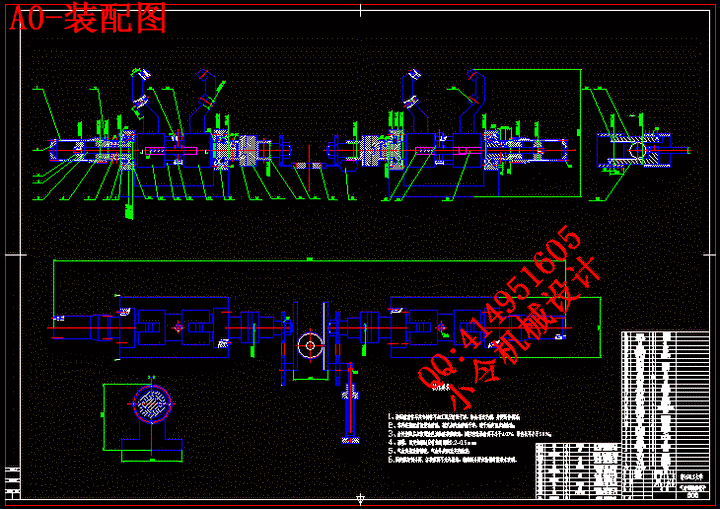
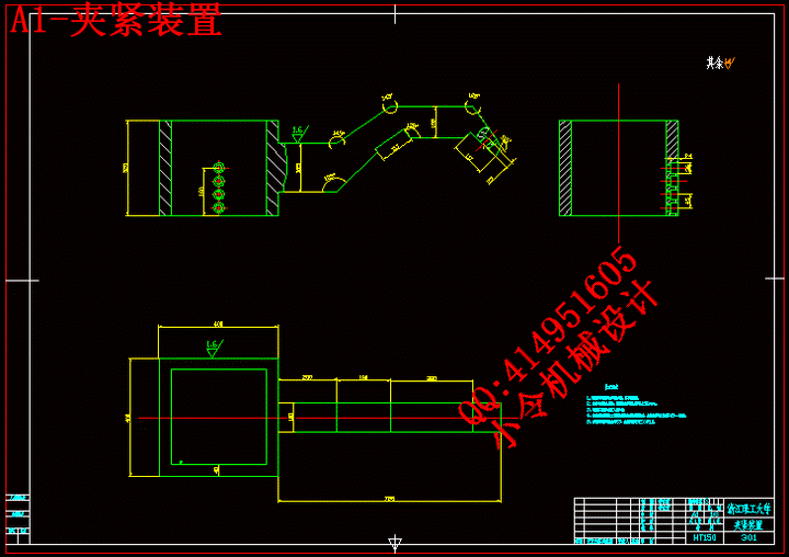
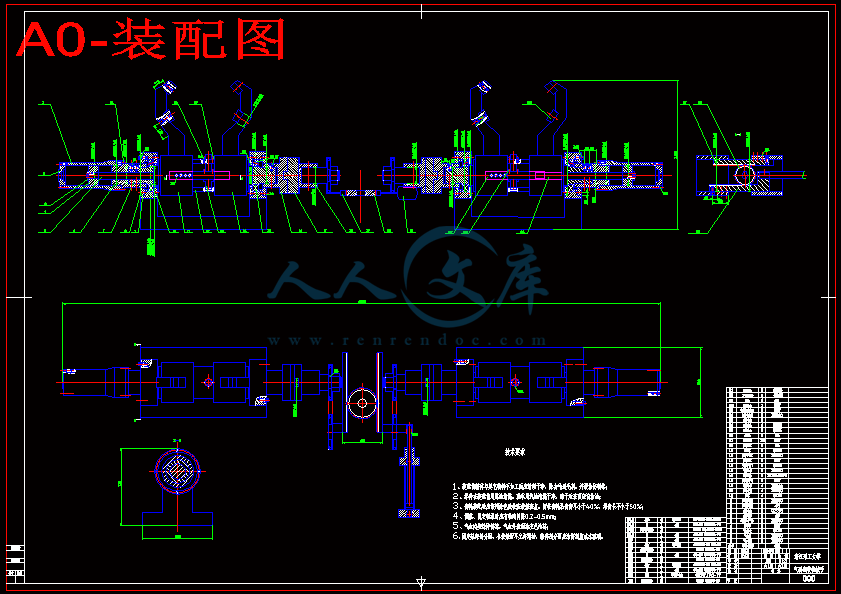
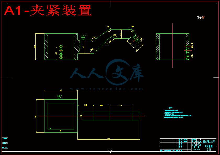
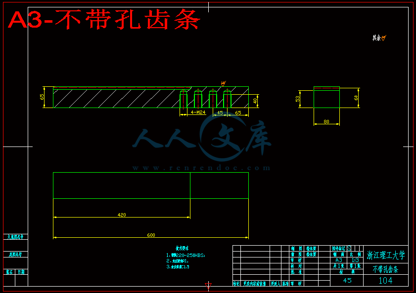
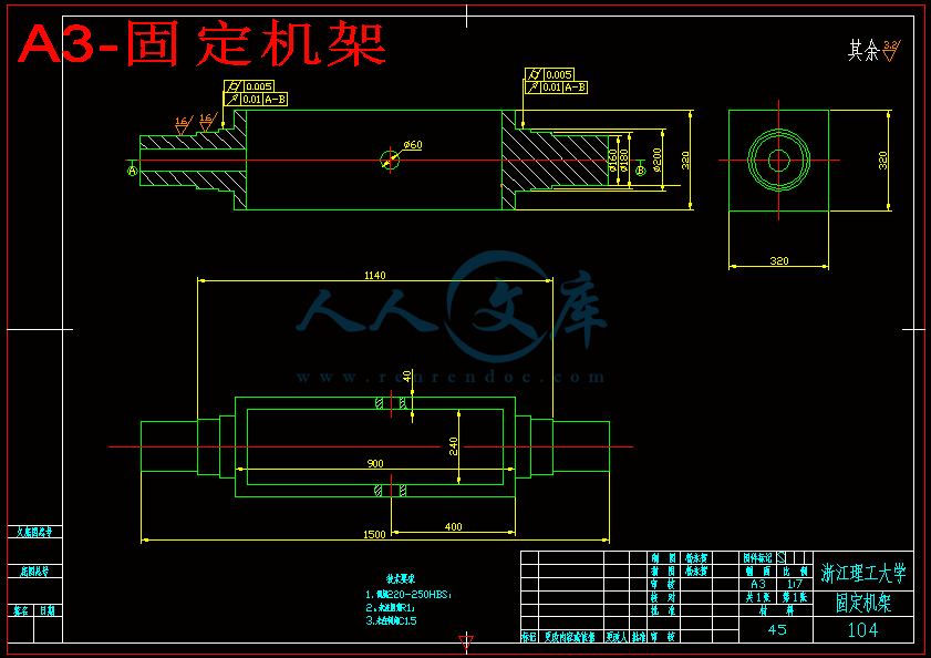
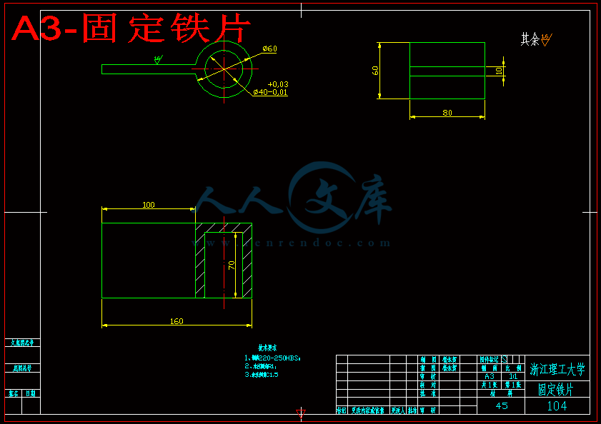
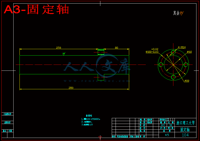
气动翻转机械手部件设计[仿真动画][PPT]【全套21张CAD图纸和毕业论文】

收藏

资源目录
跳过导航链接。
压缩包内文档预览:
预览图 预览图 预览图 预览图 预览图 预览图 预览图 预览图 预览图 预览图 预览图 预览图
编号:271534    类型:共享资源    大小:7.97MB    格式:RAR    上传时间:2014-04-07 上传人:好资料QQ****51605 IP属地:江苏
45
积分
关 键 词:
气动 翻转 机械手 部件 设计 仿真 ppt
资源描述:

【温馨提示】 购买原稿文件请充值后自助下载。

[全部文件] 那张截图中的文件为本资料所有内容,下载后即可获得。


预览截图请勿抄袭,原稿文件完整清晰,无水印,可编辑。

有疑问可以咨询QQ:414951605或1304139763



Abstract
   Pneumatic manipulator is a robot which is based on Pressure-driven. The robot is the combination of expertise and expertise of an anthropomorphic machine electro-mechanical device, not simply instead of manual labor. It owns both the rapid response to the environment state and the ability of a long continuous operation, high accuracy, and the resistance to harsh environments. It is mainly used to crawl at a fixed program, and carry objects and operate tools automatically. So Pneumatic Manipulator can reduce labor intensity, improve production efficiency. However, its disadvantages are obvious. Pneumatic Manipulator getting the precise positioning is very difficult, especially achieving multi-point positioning to anywhere because of the great compressibility of gas. Also, the compressibility limits a load to be too heavy. Traditional pneumatic system only relies on the set position of the mechanical giving location and reliable positioning and velocity which relies on a single one-way throttle. So it is often unable to meet many requirements of the automatic control equipment.
     After a deep study, we found that the pneumatic flip robot on the current production line can only be achieved crawling and flip function once in a movement process whose efficiency is too low. So we design a pneumatic flip robot which can achieve the two crawling and flipping in a motion process. There is no doubt that the pneumatic flip robot can improve work efficiency and speed up the production efficiency.
Key words:  pneumatic devices; robot; turning device; clip bottle;


目  录
摘  要
Abstract
第1章 绪论 1
1.1 引言 1
1.2气动机械手的发展 1
1.2.1国外气动机械手状况 1
1.2.2国内气动机械手情况 3
1.3发展趋势 3
1.3.1重复高精度 3
1.3.2模块化 3
1.3.3无给油化 4
1.3.4 机电气一体化 4
1.4 机械手夹持部件结构示意图 4
1.4.1 外夹持型机械手 4
1.4.2 内夹持型机械手 5
1.5国内外气动机械手设计举例 5
1.5.1与模具切割相结合 5
1.5.2 机械手虚拟样机 6
1.5.3 高精度机械手 6
第2章 气动翻转机械手总体设计 8
2.1 抓取系统的初步设计 8
2.2 翻转系统的初步设计 8
2.2.1 锥齿轮电机翻转 8
2.2.2 链轮链条气缸翻转 9
2.2.3 翻转方案选择 9
2.3气动翻转机械手的三维建模、装配思路 10
2.3.1各部分零件设计 10

2.3.2 气动翻转机械手的运动学仿真 10
2.3.3 研究思路方案、可行性分析及预期成果 11
第3章 气动翻转机械手重要零部件设计校核及其装配 12
3.1气缸的设计和校核 12
3.1.1 夹紧系统气缸设计和校核 12
3.1.2 翻转系统气缸设计和校核 14
3.2齿轮设计和校核 15
3.2.1齿轮参数的选择 15
3.2.2齿轮几何尺寸确定 15
3.2.3齿根弯曲疲劳强度计算 16
3.3齿条的设计和校核 18
3.3.1齿条的设计 18
3.4 固定机架上的轴设计和校核 20
3.4.1求输入轴上的功率、转速和转矩 20
3.4.2求作用在齿轮上的力 20
3.4.3 初步确定轴的最小直径 21
3.4.4轴的结构设计 21
3.4.5精确校核轴的疲劳强度 23
3.5圆锥滚子轴承的设计和校核 25
3.6键连接设计和校核 26
3.6.1输入轴键计算 26
3.6.2中间轴键计算 26
3.6.3输出轴键计算 27
3.7联轴器的设计和校核 27
第4章 三维建模和运动仿真 29
4.1 整体装配图 29
4.2夹紧系统装配图 29
4.3气缸推动和翻转系统装配图 30
4.4 气缸推动夹紧装置系统装配图 30
第5章 总结与展望 32

5.1总结 32
5.2展望 32
参考文献 33
致  谢 35

第1章 绪论
1.1 引言
   近20年来,气动技术的应用领域迅速拓宽,尤其是在各种自动化生产线上得到广泛应用。电气可编程控制技术与气动技术相结合, 使整个系统自动化程度更高, 控制方式更灵活, 性能更加可靠; 气动机械手、柔性自动生产线的迅速发展, 对气动技术提出了更多更高的要求;由于气动脉宽调制技术具有结构简单、抗污染能力强和成本低廉等特点, 国内外都在大力研发气动机械手。
1.2气动机械手的发展
1.2.1国外气动机械手状况
   从各国的行业统计资料来看, 近30多年来, 气动行业发展很快。20世纪70年代, 液压与气动元件的产值比约为9:1, 而30多年后的今天, 在工业技术发达的欧美、日本等国家, 该比例已达到6:4, 甚至接近5:5。
   90年代初,有布鲁塞尔皇家军事学院Y.Bando教授领导的综合技术部开发研制的电子气动机器人--"阿基里斯"六脚勘测员,也被称为FESTO的"六足动物"[12]。Y.Bando教授采用了世界上著名的德国FESTO生产的气动元件、可编程控制器和传感器等,创造了一个在荷马史诗中最健壮最勇敢的希腊英雄--阿基里斯。它能在人不易进入的危险区域、污染或放射性的环境中进行地形侦察。六脚电子气动机器人的上方安装了一个照相机来探视障碍物,能安全的绕过它,并在行走过程中记录和收集数据。六脚电子气动机器人行走的所有程序由FPC101-B可编程控制器控制,FPC101-B能在六个不同方向控制机器人的运动,最大行走速度0.1m/s。通常如果有三个脚与地面接触,机器人便能以一种平稳的姿态行走,六脚中的每一个脚都有三个自由度,一个直线气缸把脚提起、放下,一个摆动马达控制脚伸展、退回,另一个摆动马达则负责围绕脚的轴心作旋转运动。每个气缸都装备了调节速度用的单向节流阀,使机械驱动部件在运动时保持平稳,即在无级调速状态下工作。控制气缸的阀内置在机器人体内,由FPC101-B可编程控制器控制。当接通电源时,气动阀被切换到工作状态位置,当关闭电源时,他们便回到初始位置。此外,操作者能在任何一点
上停止机器人的运动,如果机器人的传感器在它的有效范围内检测到障碍物,机器人也会自动停止。
   由汉诺威大学材料科学研究院设计的气动攀墙机器人,它能在两个相互垂直的表面上行走(包括从地面到墙面或者从墙面到天花板上)。该机器人轴心的圆周边上装备着等距离(根据步距设置)的吸盘和气缸,一组吸盘吸力与另一组吸盘吸力的交替交换,类似脚踏似的运动方式,使机器人产生旋转步进运动。这种攀墙式机器人可被用于工具搬运或执行多种操作,如在核能发电站、高层建筑物气动机械手位置伺服控制系统的研究或船舶上进行清扫、检验和安装工作。机器人用遥控方式进行半自动操作,操作者只需输入运行的目标距离,然后计算机便能自动计算出必要的单步运行。操作者可对机器人进行监控。
   国外的设计人员对于机械手的设计理念已经非常成熟。Wright等人分析比较了机械手与人手抓取系统,并把机械手分成与机器人手臂和控制系统相兼容、安全抓取和握持对象、准确的完成复杂性任务三种类别。许多工厂的机械手的例子和机械手设计指导方针也被描述进去了。Pham等人总结了机械手在不同应用环境下设计方案应该如何选择。在他们的研究中,影响机械手如何选择的变量如下:(a)成分,(b)任务,(c)环境,(d)机械臂和控制条件。“成分”这个变量包括几何、形状、重量、表面质量和温度,这些因素都需要考虑好。对于可重构系统,他们以形状和大小为标准又把这个变量分成了其他家族。对于“任务”这个变量,除了机械手的类型、不同组成部分的数量、准确性及周期需要考虑外,还有主要的操作处理如抓取、握持、移动和放置都要考虑。在合适的地方设计核实的机械手,必须考虑所有的因素,而且验证性的测试必须要多做。为了减少疲劳效应,pham等人开发了一个用于选择机械手的专家系统。瑞典EIET ROIUX 公司于最近创造一种新产品一一气动机械手。这种机械手以压缩空气为动力, 小巧灵便,它装在一个圆形竖柱上, 该圆柱又能上下移动0 至150 mm , 左右移动350mm,机械手的最高速度为1000m/s,定位精度为500m/s;两个机械手各能举起5kg重物。


1.2.2国内气动机械手情况
   我国改革开放以来,气动行业发展很快。1986年至2003年间,气动元件产值的年第增率达24.2,高于中国机械工业产值平均年递增率10的水平。虽然市场和应用发展迅速,但是我国的气动技术与欧美、日本等国相比,还存在着相当大的差距。我国在气动技术的研究与开发的方面,缺乏先进的仪器与设备,研究开发手段落后,技术力量差,每年问世的新产品数量极其有限。在许多开发与研究领域还是空白,因此必须跟踪国外气动技术的最新发展动向,以减小差距,提高我国气动技术的水平。
1.3发展趋势
1.3.1重复高精度
   精度是指机器人、机械手到达指定点的精确程度, 它与驱动器的分辨率以及反馈装置有关。重复精度是指如果动作重复多次, 机械手到达同样位置的精确程度重复精度比精度更重要, 如果一个机器人定位不够精确, 通常会显示一个固定的误差, 这个误差是可以预测的, 因此可以通过编程予以校正。重复精度限定的是一个随机误差的范围, 它通过一定次数地重复运行机器人来测定。随着微电子技术和现代控制技术的发展, 以及气动伺服技术走出实验室和气动伺服定位系统的成套化。气动机械手的重复精度将越来越高, 它的应用领域也将更广阔, 如核工业和军事工业等。
1.3.2模块化
   有的公司把带有系列导向驱动装置的气动机械手称为简单的传输技术, 而把模块化拼装的气动机械手称为现代传输技术。模块化拼装的气动机械手比组合导向驱动装置更具灵活的安装体系。它集成电接口和带电缆及气管的导向系统装置, 使机械手运动自如。由于模块化气动机械手的驱动部件采用了特殊设计的滚珠轴承, 使它具有高刚性、高强度及精确的导向精度。优良的定位精度也是新一代气动机械手的一个重要特点。模块化气动机械手使同一机械手可能由于应用不同的模块而具有不同的功能, 扩大了机械手的应用范围, 是气动机械手的一个重要的发展方向。智能阀岛的出现对提高模块化气动机械手和气动机器人的性能起到了十分重要的支持作用。因为智能阀岛本来就是模块化的设备, 特别是紧凑型CP 阀岛, 它对分散上的集中控制起了十分重要的作用, 特别对机械手中的移动模块。
1.3.3无给油化
   为了适应食品、医药、生物工程、电子、纺织、精密仪器等行业的无污染要求, 不加润滑脂的不供油润滑元件已经问世。随着材料技术的进步, 新型材料(如烧结金属石墨材料) 的出现, 构造特殊、用自润滑材料制造的无润滑元件, 不仅节省润滑油、不污染环境, 而且系统简单、摩擦性能稳定、成本低、寿命长。
1.3.4 机电气一体化
   由“可编程序控制器-传感器-气动元件”组成的典型的控制系统仍然是自动化技术的重要方面;发展与电子技术相结合的自适应控制气动元件, 使气动技术从“开关控制” 进入到高精度的“ 反馈控制”; 省配线的复合集成系统, 不仅减少配线、配管和元件, 而且拆装简单, 大大提高了系统的可靠性。
   而今, 电磁阀的线圈功率越来越小, 而PLC 的输出功率在增大, 由PLC直接控制线圈变得越来越可能。气动机械手、气动控制越来越离不开PLC, 而阀岛技术的发展, 又使PLC 在气动机械手、气动控制中变得更加得心应手。
1.4 机械手夹持部件结构示意图
1.4.1 外夹持型机械手
   图1-2为一种较简单平行开闭手爪的结构。气缸的活塞有压缩空气驱动,通过活塞杆7上的支点轴2带动拨叉3转动,再通过传动轴4使手爪1沿导向槽做平行移动,图中为双作用气缸,也可为单作用气缸返回运动靠弹簧完成。该结构的特点是重量轻,体积小,最小型重量为75g,最大型为300g,因此,可以与小型机械手配套使用。


内容简介:
International Journal of Machine Tools & Manufacture 46 (2006) 13501361Design and feasibility tests of a flexible gripper based oninflatable rubber pocketsHo Choi, Muammer Koc -?NSF ERC on Reconfigurable Manufacturing Systems, College of Engineering, University of Michigan, Ann Arbor, MI 48109, USAReceived 30 January 2005; accepted 19 October 2005Available online 5 December 2005AbstractIn this paper, we present feasibility test results of a flexible gripper design following a literature survey on various types, design andcontrol strategies of the existing grippers. A flexible gripper based on the use of compliant materials (i.e., rubber) with pneumaticinflation was designed, analyzed, built and tested. Parametric FE analyses were conducted to investigate the effects of process and designparameters, such as rubber material, pressure, initial jaw displacement and friction. Based on the FEA results, a simple, single rubber-pocketed flexible gripper was designed and built. Feasibility experiments were performed to demonstrate and obtain an overallunderstanding about the capability and limitations of the gripper. It was found that objects with different shapes (cylindrical, prismaticand complex), weight (50g20kg.), and types (egg, steel hemi-spheres, wax cylinders, etc.) could be picked and placed without any loss ofcontrol of the object. The range of positioning error for two different part shapes (i.e., prismatic or cylindrical) was found to be 2090mm(translational) and 0.030.91 (rotational).r 2005 Elsevier Ltd. All rights reserved.Keywords: Gripper design; Strategies; Flexible; Selection; Robotic; Rubber1. IntroductionA gripper is an end-of-arm tooling used on robots forgrasping, holding, lifting, moving and controlling ofmaterials whenever they are not processed. Human handshave been the most common, versatile, effective anddelicate form of material handling. But, for repetitivecycles, heavy loads and under extreme environments,grippers had to be developed to substitute for humanhands. In the 1960s, after the emergence of modern robots,grippers replaced human hands on numerous occasions.Robot-gripper systems are found to be effective forrepetitive material handling functions in spite of theirinitial capital and ongoing maintenance expenses becauseof their reliability, endurance and productivity. However,the cost of grippers may be as high as 20% of a robotscost, depending on the application and part complexity 1.For manufacturing systems where flexibility is desired, thecost of a suitable gripper may even go higher since theyrequire additional controls, sensors and design needs withregards to being able to handle different parts.In the 21st century, under the influences of globalization,manufacturing companies are required to meet continu-ously changing demands in terms of product volume,variety and rapid response. flexible and reconfigurablemanufacturing systems (FMS and RMS) have emerged asa science and industrial practice to bring about solutionsfor unpredictable and frequently changing market condi-tions 2. In order to fully realize the benefits of RMS andFMS, the grippers, being one of the few direct contactswith the product at the very bottom of the manufacturingchain, must also be designed for flexibility.In the early days of robotic technology applications,most grippers were designed for dedicated tasks, and couldnot be revised for other shape, size and weight conditions.Later on, a variety of flexible gripper designs weresuggested to overcome such drawbacks. But their highcost was a barrier in addition to maintenance issues andlimitations to few materials and applications. Despite suchARTICLE IN PRESS/locate/ijmactool0890-6955/$-see front matter r 2005 Elsevier Ltd. All rights reserved.doi:10.1016/j.ijmachtools.2005.10.009?Corresponding author. Tel.: +7347637119; fax: +6465147590.E-mail address: mkoc (M. Koc -).drawbacks, cost effective flexible gripper designs havebeen always sought as a viable solution for agile materialhandling systems as an important element of the envisionedFMS and RMS. For example, assembly operations inmany industries make extensive use of dedicated grippersand fixtures. These are part-specific, and therefore, must bemodified or replaced when model changes are introduced.The cost of redesigning, manufacturing, and installingthese grippers and fixtures is substantial (on the order of$100 million per plant per year for automotive manufac-turers) and would be significantly reduced if a more flexiblealternative was developed.Inthispaper,followinganextensivereviewanddiscussion on different gripper types and design issues inthe first section, a flexible gripper design based on the useof compliant materials and internal pressure (i.e., inflatablerubber pockets) approach is introduced in the second part.This type of grippers conforms to the shape of an object bymeans of elastic gripping elements and pressurization withactive degrees of freedom. In the third section, the resultsof a parametric FEA study are presented to characterizethe performance of the selected configurations of theflexible gripper under different loading and part conditionsto determine the proper parameters setting and thematerial. Finally, in the fourth section, following theprototyping, feasibility tests conducted to characterize thelimits and capabilities of the flexible gripper are explained.2. Literature survey on gripper design and types2.1. Design methodology of grippersWright et al. 3 compared the grippers to the humangrasping system, and categorized the design requirementsof grippers into (a) compatibility with the robot arm andcontroller, (b) secure grasping and holding of the objects,and (c) accurate completion of the handling task. Manyindustrial examples of grippers were also described, and theguidelines for gripper design were presented. Pham et al. 1summarized the strategies for design and selection ofgrippers in different application cases. In their study, thevariables affecting the selection of a gripper were listed as:(a) component, (b) task, (c) environment, (d) robot armand control conditions. The component variables includegeometry, shape, size, weight, surface quality and tempera-ture of objects to be handled. For reconfigurable systems,they divided these components into part families accordingto their shape and size. For the task variables, type ofgripper, number of different parts, accuracy, and cyclewere considered in addition to major handling operationssuch as pick, hold, move and place. For the right gripperdesign at the right place, all aspects should be considered,and multiple validation tests should be conducted. Toreduce this exhaustive effort, Pham et al. 4 developed anexpert system for selecting robot grippers. They built ahybrid expert system that employs both rule-based andobject-oriented programming approaches.2.2. Gripper types and classification by driving forceGrippers could be also classified with respect to theirpurpose, size, load, and driving force. Typically, grippermechanisms and major features are defined by their drivingforces. The driving forces for robot grippers are usuallyelectric, pneumatic, hydraulic; or in some cases, vacuum,magneto-rheological fluid and shape memory, etc.Grippers with electric motors have been used since 1960,abreast with robot technology. Many other grippersadopted motor driven mechanisms. Basically, this type ofsystems included step motors, ball screws, encoders,sensors and controllers. As the arms approach the object,distance, force, weight and slip are detected by sensors. Atthe same time, a controller regulates the force, speed,position and motion. Friedrich et al. 5 developed sensorygripping system for variable products. They used multiplesensors to measure the grasping force, weight and slip.Mason et al. 6 and Kerr et al. 7 presented thefundamentals of grasping with multi-fingered hands. Leeet al. 8 comprehensively reviewed the field of tactilesensing. For contact and slip, Tremblay et al. 9 consideredslip detection, and Howleg et al. 10 divided slip into fourstages; pre-slip tension, slip-start, post-movement, and stopto better analyze grasping of parts.Another way of actuating the robot gripper is throughpneumatic (or hydraulic) systems. Pneumatic systems havebeen developed because of their simplicity, cleanliness andcost-effectiveness. Warnecke et al. 11 and Wright et al. 3developed a soft pneumatic gripper which can handle softmaterials such as eggs. Ottaviano et al. 12 developedgrasp-force control in two-finger grippers with pneumaticactuation. They proposed force control in a two-fingergripper with a sensing system using commercial forcesensors. A suitable model of the control scheme has beendesigned to control thegrasping force.Experimentsshowed the practical feasibility of two-finger grippers withforce controlled pneumatic actuation 12. Lane et al. 13used hydraulic force for a sub-sea robot hand. They offerednaturalpassivecompliancetocorrectforinevitablepositioning inaccuracy with simple design and minimummoving parts. The gripper finger relied on the elasticdeformation of cylindrical metal bellows with thin con-voluted walls. The convolution ensured that the assemblywas significantly stiffer in the radial direction than thelongitudinal one. Therefore longitudinal extension wasmuch greater than radial expansion when subjected tointernalhydraulicpressure.Themodularfingertipcontained a variety of sensors and interfaces. The fingertip contact zone contains both a strain gage and apiezoelectric vibration sensor. Closed-loop position controlwas used. It was driven by hydraulic pressure measuredfrom sensors within each tube 13.Grippers based on vacuum forces are designed and usedmainly for deformable and lightweight part handling.Kolluru et al. 1417, for example, used suction-basedcontrol for handling limp material without distortion,ARTICLE IN PRESSH. Choi, M. Koc - / International Journal of Machine Tools & Manufacture 46 (2006) 135013611351deformation or damage. They developed a fixed-sizedgripper and also a reconfigurable gripper system withsuction units. A sensor-based control system based on thehierarchical control architecture controlled the operationof the robotic gripper system. Fixed dimension gripperswere developed for stacking dissimilar-sized panels ofclothes. A fuzzy controller computes the needed suctionand control depending on material porosity, weight, robotspeed, and travel distance.Rong et al. 18 presented flexible fixtures based on theuse of phase-changing materials that change the phasefrom liquid to solid upon application of electricity orelectromagnetism (known as magneto-rheologicalMRfluid). Bertetto et al. 19 made a two-degree of freedomgripper actuated by shape memory alloy (SMA) with aflexure hinge in micro scale. They designed NiTi SMAgripper and the test showed to be able to reach designperformance. The SMA has some drawback when it isapplied to high working bandwidth, because of its thermalresponse 19.2.3. Control algorithm development for grippersA basic role of the gripper is grasping an object securely.For this purpose, many researchers have investigated onconstraining algorithms. Asada et al. 20 presented formclosure grasping by a reconfigurable universal gripper.They applied the form closure concept to grasping awork-piece. They analyzed kinematic conditions for totallyconstraining an object which is assumed to be piece-wisesmooth. An efficient algorithm for examining the totalconstraint was also devised. The gripper had reconfigurablefingers consisting of a multi-degree of freedom linkmechanism. It had the capability of changing the config-uration of individual fingers so that the finger tip could belocated at an appropriate position depending on the shapeof the work-piece 20. Yoshikawa et al. 21 provided aunified theoretical framework for grasping and manipula-tion by robotic grippers and hands as well as for fixingworks by fixtures and vises. They introduced the concept ofpassive closure and active closure. Passive closure wasdivided into passive form closure and passive force closure.They studied conditions for these closures to hold an objectsecurely 21. Wallack et al. 22 developed an algorithm forplanning planar grasp configuration for the modular vise.Brown et al. 23 expanded that work to produce a 3-Dfixture and gripper design tool. They described severalanalyses, and added a 2-D algorithm, 3-D grasp qualityandgeometricloadinganalyses.Theyshowedsomeapplications and potential uses of their code in an agileassembly line 23. Qian et al. 24 presented an efficientalgorithm for computing object poses in a modular fixturegripper. They introduced efficient algorithms for com-puting poses of given objects. The computer programshowed universal application, running fast and accurateresults 24.After gripping, alignment of a part for assembly ormachining purpose is needed. Kaneto et al. 25 showed apractical procedure for achieving an enveloping grasp. Itconsists of several phases including approach, lifting,grasping and coordinate phases. The experiment alsoshowed the effectiveness of the proposed grasping proce-dure. Zhang et al. 26 showed an alignment of parts duringgrasping using a standard parallel-jaw gripper. They usedfour gripper point contacts that will align the part in thevertical plane as the jaws close. The algorithm for partalignment includes toppling, accessibility, and form-closureanalysis 26.As mentioned in the gripper design section, grippersshould be compatible with the robot and controller. Thecontrol system could vary according to its purpose,constraining algorithm, environment, and condition. Itcould be an independent and subordinate system based onthe purpose. The control system could also vary based onthe sensors and actuators that are adopted. For example,Kolluru et al. 15 used vision and optical sensors for agripper system. In their case, the gripping process iscomposed of two steps. First, the gripper is coarselypositioned by means of a vision sensor. Second, finealignment is measured and controlled using an opticalARTICLE IN PRESSFig. 1. Conceptual models of flexible gripper designs with rubber pockets, movable/adjustable jaws and additional pin locators, etc; (a) three rows ofvertical rubber pockets, (b) hemispherical rubber pockets, and (c) single rubber pocket design. In all cases, note the multiple holes and pins on the upperplate.H. Choi, M. Koc - / International Journal of Machine Tools & Manufacture 46 (2006) 135013611352sensor array. For an integrated robotic gripper system,they also suggested hierarchical control architecture andfuzzy logic formulation. For manipulating payloads withmultiple robots, Sun et al. 27 described an approach tonon-model based controls of multi-robot systems.2.4. Flexible gripping strategiesIn terms of accomplishing flexible gripping tasks, fivedifferent strategies were suggested by Pham and Yeo 1 toachieve the flexibility in a cost-effective manner. The firstkind of gripper gains its flexibility from a number ofnotches on the gripping surfaces so that objects withvarious shapes can be handled. Obviously, notching ofgripper fingers is only suitable for the parts of similar sizeand weight. Another flexible gripper concept is based oninterchangeable gripper fingers. This method is moreflexible and reliable than notching method when thegripper is equipped with a finger changing apparatus anda standard set of fingers. Another strategy is to change thegripper itself. This method can be used when a singlegripper cannot handle a whole set of parts with differentsizes, geometries and weights. These grippers need variouschanging systems for locking and unlocking grippers. Thismethodismore complexandexpensivethanotherstrategies. Finally, use of multiple grippers was alsosuggested. Multiple grippers are attached on revolving orsliding mechanisms. This technique could reduce timecomparing to gripper changing technique. But, it is obviousthat the pay load increases in proportion to the numbersof grippers. Therefore, it is more suitable for lightpayload applications such as electronics and small precisemachining.Universal grippers are also suggested to be a viableway of handling a wide range of objects with differentshapes and weight 1. The universal grippers are groupedinto two categories: active and passive grippers. Passivegrippers automatically conform to the shape of the objectsby means of gripping elements which are elastic or havepassive degrees of freedom. It was reported that, withpassive gripping, it is difficult to ensure the precise positionof the gripped object with respect to the robots coordinateARTICLE IN PRESS00.511.522.533.544.550100200300400500600700Strain (%)Stress (MPa)100% modulus1.7 MPa300% modulus2.9 MPaFig. 3. Flow stress curve of neoprene rubber material used in the FEanalyses 27.Table 1Coefficient of friction of neoprene rubber with different part materialsMaterialCoefficient of static friction on rubberWax0.5970.01Aluminum0.6670.01Steel0.6970.01Fig. 4. FE model, initial conditions (DD- Initial distance btw jaws) andmeasurement (Dy-vertical displacement of part during gripping).Fig. 2. FE models of two conceptual flexible gripper designs: (a) singlerubber pocket and (b) multiple rubber pockets.H. Choi, M. Koc - / International Journal of Machine Tools & Manufacture 46 (2006) 135013611353system. In one specific case 28, the gripper surface iscovered with a membrane comprised or cubic cells filledwith compressible fluid. The cells are separated by a flexiblebut non-elastic material. After the initial contact is made,the robot applies a force to simultaneously compress andlift the part. A shear force will be introduced by thisparticular manner of applying the force. When the liftingforce and gripping force are increased, the distortion willalso increase until the friction force is large enough to liftthe part. At this point, the distortion will reach itsmaximum. After that the distortion will decrease whenthe cells are further compressed by increasing the grippingforce because of the tendency of fluid inside the cells tomaximize its volume. The magnitude of the distortion ismonitored with shear force sensors. Thus, the point wherethe distortion decreases is the point at which it is time topick up the object. Key idea of this kind of gripper is toimitate the basics of a human hand. Although thesegrippers are so amazing and can ideally handle any kindsof part, at least in short term, active grippers are expensive,unreliable, and not a good fit for industrial use.3. Design, analysis and fabrication of a flexible gripperbased on inflatable rubber pocketsIn order to complement the efforts and realize the fullbenefitsof reconfigurableand flexible manufacturingsystems, we made an attempt to design, prototype andvalidate a flexible gripper system based on pneumaticallyinflated rubber pockets concept. In this section, design andanalysis of the flexible gripper are presented in detail.The requirements for the desired flexible gripper systemcan be summarized as follows: it should be (1) able handleparts with different shapes, sizes and weights, (2) durable,(3) highly accurate and repeatable in terms of placementpositioning (less than 100mm), (4) cost-effective, and (5)easy to implement and maintain. The targeted part sizeenvelope was 60 (w)?70 (d)?90 (h)mm, and the weightrange was between 50g (i.e., wax) and 3Kg (steel).We adopted the pneumatically inflatable rubber pocketsthat are compliant to different shapes in order to handledifferent shapes, size and weight. Fig. 1 illustrates variousconceptual designs generated based on this idea. In general,for all conceptual designs, rubber pocket(s) are embeddedARTICLE IN PRESSTable 2Factors and their levels considered in the FE analyses (Ppressure, DDinitial distance btw jaws, and Wpart weight), and response (Dy)Factors and levelsResponseInitial distancebtw jaws (DD,mm)Internal pressure(P, kPa)Weight of part(W, kg)3.0150.06Verticaldisplacement ofpart (Dy, mm)7.5650.78121151.50Fig. 5. Effect of process (pressure), part (weight) and initial conditions (initial distance between jaws) on the vertical displacement (positioning error) ofthe part (Dy).H. Choi, M. Koc - / International Journal of Machine Tools & Manufacture 46 (2006) 135013611354on to the hard jaw plates using clamps for various partsizes. Screw-type stoppers are designed to adjust the spacebetween jaws. By changing the rubber-pocket pressure, thegripper could handle parts with different shapes andweights. In order assure an accurate part positioningduring placement, multiple pins embedded into the upperplate are envisioned. The location and size of these pins canbe changed easily to ensure placement positioning ofdifferent parts.Fig. 1a shows a gripper that has a several verticallyalignedrubberpockets.Tosecureandreducethepositional error of part handling and to increase thereliability, three rubber pockets were conceptualized ineach side of the gripper. This type of design could beadopted especially for the parts with shape complexitiessuch as grooves or caves in the side walls. In anotherconceptual gripper design of similar type, multiple mush-room (dome-like) rubber pockets are placed on the jaws tohandle the parts with complex surface shapes as shown inFig. 1b. The concave and convex regions of the multiplerubber pockets are thought to play a major role to grabcomplex-shaped parts securely by the increased surface (i.e.contact) area as the domes are inflated and gets in contactwith the object. Finally, a simpler version is designed asdepicted in Fig. 1c. In this case, a large pocket is designedin each side of the gripper for simplicity.In order to demonstrate the feasibility of the conceptua-lized flexible grippers based on inflatable rubber pocketsapproach, a number of FE analyses were conducted beforethe detailed design and prototyping efforts. Only two typesof the conceptual designs were considered in the analyses.First, the flexible gripper with a single rubber pocket (Figs.1c and 2a) was modeled in 2D and analyzed under differentpressure, part weight and initial conditions. Second, theARTICLE IN PRESSTable 3Factors and their levels considered in the second set of FE analyses (Ppressure, DDinitial distance btw jaws, and Wpart weight), and response (Dy)Case #123UnitResponse 1Response 1DD333mmVertical displacement of thepart (Dy, mm)Horizontal displacement of thejaw (Dx, mm)P1156565kPaW0.780.061.5kgIn this case, elastic deflection of jaws was taken into account in addition to the effects of non-flat parts and double-rubber pockets.Fig. 6. Results of FE analyses for three cases (different DD, P and W as listed in Table 3) under four different conditions (rigid vs. elastic jaws, single vs.double rubber pockets, and flat vs. non-flat part).H. Choi, M. Koc - / International Journal of Machine Tools & Manufacture 46 (2006) 135013611355flexible gripper with multiple rubber-pockets (Figs. 1b and2b) was studied. In order to accurately model the grippinginterface with the gripper material and the object to behandled, the friction coefficient between two different typesof rubber (neoprene and butyl) and three different partmaterials (aluminum, steel and wax) were first experimen-tally determined as listed in Table 1. Basically, differentobject materials of simple shapes (cylindrical and pris-matic) were gripped at different pressure values. Then, theobject is pulled down. The force required to move theobject and the displacement were measured. Based on theseARTICLE IN PRESSTable 4Specifications of the flexible gripper based on single-rubber pocket conceptNameDescriptionMaterial of gripper body, MAluminumMaterial of air-pocketButyl or neoprene rubberJaw actuatorPneumatic, 600KPaRubber-pocket pressure, P0600KPa (087psi)Range of initial space betweenjaws, D4564mm (1.772.51 inch)StopperFixed screw typeFig. 8. Dimensions of the designed flexible gripper (L 95mm, a b d 51mm, c 70mm, D 45264mm, DD is the initial distance between jawand the part while A is the characteristic size of the part): (a) front view of the flexible griper and (b) side view of a jaw.Fig. 7. Flexible gripper; (a) selected conceptual model, (b) assembled gripper, and (c) gripper attached to a robot.H. Choi, M. Koc - / International Journal of Machine Tools & Manufacture 46 (2006) 135013611356two values and the geometry, average friction coefficientswere calculated. Similarly, the material model of rubberwas constructed based on the data obtained from MatWebfor neoprene 29 as depicted in Fig. 3. A hybrid elementtype (C3D8H, fully incompressible hyper-elastic material)was used to model the rubber material. The thickness of therubber was considered to be 1.6mm whereas the side platethickness was 18mm. Fig. 4 illustrates the FE model,definition of the initial conditions (i.e., initial distancebetween jaws), and the measurement of vertical partdisplacement during gripping (Dy), whereas Table2presents the factors considered in the FE analyses (valuesof initial distance between jaws, pressure and part weight),their ranges and levels as well as the response.ARTICLE IN PRESSTable 5Specifications of the parts used in the feasibility testsPart typeMaterialWeightSizeHemispherical part, Fig. 9aSteel5kg60?90?70mm (w, h, d)Stepped cylindrical part, Fig. 9bAluminum1kg60?90mm (OD, h)Prismatic wax part, Fig. 9cWax67gr30?30?60mm (w, h, d)Cylindrical wooden part, Fig. 9dWood300gr70?90mm (OD, h)Egg, Fig. 1050gr30?50mm (OD, h)Fig. 10. Illustration of pick and place operation with an egg without damaging or breaking it.Fig. 9. Tested part types (shape and weight).H. Choi, M. Koc - / International Journal of Machine Tools & Manufacture 46 (2006) 135013611357As a result of the first set of FE analyses conductedaccording to the matrix in Table 2, we can conclude that(as shown in Fig. 5) excessive initial distance between jaws(DDm) leads to poor handling (Dym) of the part particu-larly when the part is heavy (Wm) and pressure is notsufficient (Pk). The optimal handling (i.e., minimal partdisplacement, Dy) conditions can be achieved when theinitial distance between the jaws (DD) is around 78mmand pressure (P) is at its medium levels (6070KPa) for apart weight of around 1.5kg (W). When the part is light(?100500g), optimal handling conditions are found to bewhen the pressure is at low levels (50KPa) while the initialjaw displacement is around 67mm. However, it should benoted that optimal conditions may change for heavier andmore complex-shaped parts since the friction conditionsbetween the part and rubber would change.In the second set of FE analyses, elasticity of the jaws (sideplates) was also taken into account in addition to the effectsof double-rubber pocket and non-flat parts. Thus, besides thevertical displacement (Dy) of the part, horizontal displace-ment (Dx) of the jaw was also measured and reported in theFE analyses. Three different cases of (DD, P and W) wereconsidered as presented in Table 3 and Fig. 6. As it can beobserved in this figure, elasticity of jaws affect the parthandling accuracy considerably when Fig. 6a and b arecompared for a single pocket and flat part type case.Regardless of the process conditions (DD, P, W), vertical andhorizontal displacements increase 48 times (to 2040mmfrom 5mm and below). It should be noted, in the case of rigidjaws (Fig. 6a), there is no horizontal displacement. A similartrend in the increase of part displacements is also observedfor non-flat part as depicted in Fig. 6c. However, upon use ofdouble-rubber pockets, as shown in Fig. 6d, displacementerrors particularly in the vertical direction are reduced downto 10mm levels. Horizontal displacement is slightly decreasedby the use of double pockets since the rubber materialconform to the part shape. In summary, as a result of the FEanalyses, we can conclude that:(1) The concept of inflatable rubber-pockets for flexiblegripping is feasible.(2) Range of placement errors was predicted to be between40 and 75mm under different pressure and part weightcircumstances.(3) Multiple rubber-pocket approach is potentially moredesirable to reduce part handling errors.(4) However, manufacturing (i.e., molding) of small mush-room-like pockets would be too costly and lengthy.Therefore, for prototyping and feasibility experiments,a flexible gripper with single-rubber pockets wasselected due to its simplicity, relatively low cost andeasy interchangeability and maintainability.Detailed specifications of the designed gripper are listedin Table 4. A three-dimensional rendering of the flexiblegripper, its physical prototype and assembly onto the robotare shown in Fig. 7, while Fig. 8 presents the dimensions.The designed flexible gripper operates in two phases. First,it roughly encloses the part with parallel-jaws (size plates)approaching to the part without any contact. Secondly, therubber pockets attached to parallel-jaws are inflated tograsp and hold the part securely. By controlling the initialjaw displacement (DD) and pressure (P), various partshapes and weight can be handled accurately and softly.4. Feasibility tests on the flexible gripperVarious tests at different levels were performed to verifythe feasibility of the flexible gripper. First, in order todemonstrate that it could handle a variety of part shapes,parts with different shapes were picked, moved and placedwithout any handling problems such as slippage, dropping,or breakage, as shown in Fig. 9. For instance, around twodozens of eggs were picked and placed repeatedly withoutdropping and damaging as depicted in Fig. 10. In thesecond level, we tested the sensitivity of the gripperparameters on different part types. We changed thepressure between 30 and 80KPa, initial jaw distanceARTICLE IN PRESSFig. 11. Test setup used for measuring the maximum weight that could behandled by the gripper.Table 6Maximum part weight lifted by gripper as a function of pressurePressureMaximum part weight34kPa (5psi)12kg (27lbs)138kPa (20psi)31kg (70lbs)Table 7Experimental conditions for the measurement of displacement errorsCase 1Case 2Case 3Part shapeCylindricalPrismaticPrismaticPart weight (kg)0.0571.51.5P (kPa)135596DD (mm)7.544MaterialNeopreneNeopreneNeopreneH. Choi, M. Koc - / International Journal of Machine Tools & Manufacture 46 (2006) 135013611358between 3 and 7mm, and used two different rubbermaterials (neoprene and butyl), and checked their effecton the handling of different part shape and size. Table 5presents the specifications of the tested parts which rangefrom a hemispherical shapes steel part of 5Kg. to eggs of50g. Third, the limits of part size and weight were tested. InARTICLE IN PRESS errorerror Diagonal(X0, Y0)(X1, Y1)Target positionActual positionAngular0.08780.01730.01290.0000.0500.1000.1500.2000.250case 1case 2case 3case 1case 2case 3Diagonal error(mm) 0.01370.03950.94370.0000.5001.0001.5002.0002.500Angular error(deg.) Fig. 12. Measured placement error of the flexible gripper and its variation under different pressure conditions. Table 7 presents the experimentalconditions. For both diagonal and angular errors, Case #2 and #3 results in very small values and variation.001234567951015202530354010NeopreneButy l rubberFailure11# of inflation cycles (x103)Expansion of rubber pocket (mm)NeopreneButyl rubberFailuree: Expansion ofrubber pocketPFig. 13. Cyclic durability test results for neoprene and butyl rubber materials (expansion versus number of inflation cycles).H. Choi, M. Koc - / International Journal of Machine Tools & Manufacture 46 (2006) 135013611359order to test the limits of part weight that can be handled, asimple method was used where a scale was attached to apart that was held by the gripper as illustrated in Fig. 11.At different pressure values and rubber material condi-tions, the part is then pulled down until it is moved. Theforce reading at that moment recorded as the maximumweight that can be handled. It was found that with aninternal pressure of 34KPa, parts up to 12kg can behandled. When the pressure was increased to 138KPa, partweight limit also increased to 31kg as listed in Table 6.Fourth, to validate the handling accuracy of the flexiblegripper, the positional error in diagonal and angulardirections were measured using an optical measurementsystem. Basically, the distance and rotation between target(designed) position and actual position of the part after itwas placed was measured. Two kinds of parts, cylindrical(56g) and prismatic (1.5Kg) parts were used with variousinitial jaw distance and pressure as presented in Table 7.The results are shown in Fig. 12. For the light cylindricalpart, the placement error was 90mm in diagonal and 0.91 inangular directions whereas for the heavy prismatic part, theerrorwas10mmindiagonaland0.041inangulardirections. When we compare Case #2 and #3, Case #3has slightly larger error than Case #2, although they are forthe same part as shown in Fig. 12 and Table 7. Thedifference was due to the higher-pressure application at agiven initial jaw distance for Case #3. Similar trend wasalso predicted previously by FE analyses.Finally, it was observed that type of rubber material didnot affect the weight limitations. However, as observed atthe end of cyclic inflation tests (Fig. 13), neoprene materialyielded at around 2800 cycles of inflation following agradual increase in its expansion ratio up to 36mm fromwhere as butyl lasted more than 10,000 cycles of inflation ata consistent expansion of 13mm.5. Results and conclusionsIn this paper, after a review of the existing gripper typesand design strategies, design stages of a flexible gripperbased on inflatable rubber pockets concept were explained.Results of numerical analyses on the performance of asimple conceptual design case were presented to reflect thepotential effects of process and rubber material on the parthandlingaccuracy. Finally,uponmanufacturingandinstallation a prototype flexible gripper onto a robot,feasibility experiments were performed to demonstrate andobtain an overall understanding about the capability andlimitations of the gripper. It was found that:(1) The designed flexible gripper can handle parts of(a) various shapes ranging from simple cylindricalparts to complex-shaped parts,(b) different weight ranging from 50g to above 30kg,(c) any size in an envelope of 60?90?70 (w, h, d)mm.(2) The range of the errors for picking and placing parts(prismatic or cylindrical) were 2090mm in diagonaland 0.030.91 in angular direction.(3) Rubber material type does not affect the part weightlimitation, but butyl rubber shows a superior durabilityand consistent expansion under cyclic inflation testscompared to neoprene. Thus, selection of rubbermaterial is crucial for accuracy and maintenanceaspects.(4) Design of other elements of the flexible gripper mayalso affect the accuracy of part handling. Thickness andelasticity of the side plates (jaws), and also the top plateand its joint to the side plates play an important role indecreasing the deflection of the side plates whenpressure is applied into the rubber pockets, thus, ontothe side plates. During the feasibility tests, slightopening of the side plates was observed. Similardeflection was also predicted in the 2D FEA when sideplate elasticity was taken into account.(5) As a future work, experimental validation of repeat-ability and accuracy of the flexible gripper will beperformed to fully characterize its capabilities.(6) Finally, in order to increase the accuracy and repeat-ability of the flexible gripper, a three or four-fingerapproach can be used particularly to handle round-likeARTICLE IN PRESSFig. 14. (a) Next generation design of flexible gripper based on inflatable rubber pockets using three-finger approach and (b) conceptual design of aflexible fixture designed based on the same idea.H. Choi, M. Koc - / International Journal of Machine Tools & Manufacture 46 (2006) 135013611360and irregularly shaped parts as depicted in Fig. 14a.Moreover, a similar approach seems feasible to achieveflexible fixtures for assembly, inspection and machiningprocesses provided that higher levels of pressure, maybe hydraulic, are available as shown in Fig. 14b.AcknowledgmentsThe authors are pleased to acknowledge the financialsupport of the NSF Engineering Research Center forReconfigurable Manufacturing Systems (NSF Grant #EEC-9529125).References1 D.T. Pham, S.H. Yeo, Strategies for gripper design and selection inrobotic assembly, International Journal of Production Research 29(2) (1991) 303316.2 Y. Koren, U. Heisel, F. Jovane, T. Moriwaki, G. Protschow, G.Ulsoy, H.V. Brussel, Reconfigurable Manufacturing Systems, CIRPAnnals 48 (2) (1999) 527540.3 P.K. Wright, M.R. Cutkosky, Design of gripper, Handbook ofIndustrial Robot, 1985, pp. 96111.4 D.T.Pham,E.Tacgin,Anexpertsystemforselectionofrobot grippers, Expert System with Application, vol. 5, 1992,pp. 2893005 W. Friedrich, P. Lim, H. Nicholls, Sensory gripping system forvariable products. in: Proceedings of IEEE International Conferenceon Robotics and Automation, San Francisco, 2000, pp. 19821987.6 T. Mason, J.K. Salisbury, Robot Hands and the Mechanics ofManipulation, MIT Press, Cambridge, MA, 1985.7 J. Kerr, B. Roth, Analysis o
温馨提示:
1: 本站所有资源如无特殊说明,都需要本地电脑安装OFFICE2007和PDF阅读器。图纸软件为CAD,CAXA,PROE,UG,SolidWorks等.压缩文件请下载最新的WinRAR软件解压。
2: 本站的文档不包含任何第三方提供的附件图纸等,如果需要附件,请联系上传者。文件的所有权益归上传用户所有。
3.本站RAR压缩包中若带图纸,网页内容里面会有图纸预览,若没有图纸预览就没有图纸。
4. 未经权益所有人同意不得将文件中的内容挪作商业或盈利用途。
5. 人人文库网仅提供信息存储空间,仅对用户上传内容的表现方式做保护处理,对用户上传分享的文档内容本身不做任何修改或编辑,并不能对任何下载内容负责。
6. 下载文件中如有侵权或不适当内容,请与我们联系,我们立即纠正。
7. 本站不保证下载资源的准确性、安全性和完整性, 同时也不承担用户因使用这些下载资源对自己和他人造成任何形式的伤害或损失。
提示  人人文库网所有资源均是用户自行上传分享,仅供网友学习交流,未经上传用户书面授权,请勿作他用。
关于本文
本文标题:气动翻转机械手部件设计[仿真动画][PPT]【全套21张CAD图纸和毕业论文】
链接地址:https://www.renrendoc.com/p-271534.html

官方联系方式

2:不支持迅雷下载,请使用浏览器下载   
3:不支持QQ浏览器下载,请用其他浏览器   
4:下载后的文档和图纸-无水印   
5:文档经过压缩,下载后原文更清晰   
关于我们 - 网站声明 - 网站地图 - 资源地图 - 友情链接 - 网站客服 - 联系我们

网站客服QQ:2881952447     

copyright@ 2020-2024  renrendoc.com 人人文库版权所有   联系电话:400-852-1180

备案号:蜀ICP备2022000484号-2       经营许可证: 川B2-20220663       公网安备川公网安备: 51019002004831号

本站为文档C2C交易模式,即用户上传的文档直接被用户下载,本站只是中间服务平台,本站所有文档下载所得的收益归上传人(含作者)所有。人人文库网仅提供信息存储空间,仅对用户上传内容的表现方式做保护处理,对上载内容本身不做任何修改或编辑。若文档所含内容侵犯了您的版权或隐私,请立即通知人人文库网,我们立即给予删除!