外文翻译--一个短期课程自动变速器.doc

Polo轿车三轴五档手动变速器设计【4张CAD图纸】【优秀】

收藏

压缩包内文档预览:
预览图 预览图 预览图 预览图 预览图 预览图 预览图 预览图 预览图 预览图 预览图 预览图 预览图 预览图 预览图 预览图 预览图 预览图 预览图
编号:300215    类型:共享资源    大小:1.26MB    格式:RAR    上传时间:2014-07-30 上传人:上*** IP属地:江苏
45
积分
关 键 词:
polo轿车 三轴五档 手动 变速器 设计 cad图纸
资源描述:

Polo轿车三轴五档手动变速器设计

48页 15000字数+说明书+外文翻译+6张CAD图纸【详情如下】

Polo轿车三轴五档手动变速器设计论文.doc

三轴五档变速器装配图.dwg

变速器操纵机构装配图.dwg

外文翻译--一个短期课程自动变速器.doc

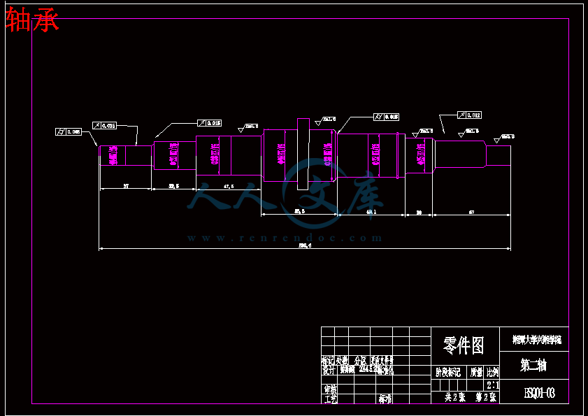
轴承.dwg

齿轮.dwg

摘  要

   本设计的任务是设计一台用于轿车上的五档手动变速器。合理的设计和布置变速器能使发动机功率得到最合理的利用,从而提高汽车动力性和经济性。变速传动机构的主要作用是改变转距和转速的数值和方向;操纵机构的主要作用是控制传动机构,实现变速器传动比的改变,即实现换挡,以达到变速变距。

   本文参阅了国内外大量文献,首先简单地叙述了机械式变速器的发展历史、变速器的地位和作用,讨论了其现状以及未来发展趋势。进而研究了机械式变速器的基本结构和变速原理,其中重点研究了传动机构(主要是轴和齿轮)的基本结构、特点及工作原理,对机械式变速器各挡传动路线进行了简要分析。文章包括大量的计算过程,具体内容有:变速器的布置方案分析、变速器回转件结构参数的确定、同步器的结构及工作原理、各挡齿轮的强度校核、轴的强度校核、轴承的使用寿命计算等。

关键词 齿轮、同步器、变速器

Abstract

   This design task is to design a car for five manual shift transmission. Reasonable design and decorate transmission can make the engine power to get the most reasonable use of, so as to improve the dynamic performance and fuel economy cars. Variable speed transmission's main function is to change the torque and speed of numerical and direction; Operation is the main purpose of control transmission mechanism, realize the transmission ratio of the gearbox change, which realize the shift, in order to achieve the change from the speed.

   This article refer to the domestic and foreign many papers, and first simply describes the mechanical transmission of the history, the status and effect of the transmission, and discussed its present situation and future development trend. And then we study the basic structure of the mechanical transmission and variable speed principle, which focus on the transmission mechanism (mainly shaft and gear) the basic structure, characteristic and work principle, mechanical transmission of each block transmission line are briefly analyzed. The articles included a large amount of calculation process, and the specific contents: the layout of transmission analysis, the transmission structure paramete  determination of turning a synchronizer, the structure and the working principle, each block of the gear axis strength check, the intensity, the service life of the bearings calculations, etc.

Keywords  Gear, Shaft, Synchronizer, Three axis five gear  

目  录

摘  要I

AbstractII

第1章  绪论1

1.1 本设计的目的和意义1

1.2 变速器的发展1

1.3变速器的设计要求3

1.4设计内容与思路3

1.4.1设计内容3

1.4.2设计思路4

1.5本章小结4

第2章  变速器的整体结构方案设计5

2.1变速器传动机构的型式选择与结构分析5

2.1.1变速器传动方案的比较5

2.1.2倒档的布置方案6

2.2本章小结7

第3章 变速器主要参数的选择与齿轮设计9

3.1变速器主要参数的选择9

3.1.1档位数和传动比9

3.1.2中心距10

3.1.3齿轮模数11

3.1.4压力角α、螺旋角β和齿宽b12

3.1.5齿轮的变位系数13

3.2各档传动比及其齿轮齿数的确定13

3.2.1确定一档齿轮的齿数13

3.2.2确定常啮合齿轮副的齿数14

3.2.3确定其他档位的齿数15

3.2.4确定倒档齿轮的齿数15

3.2.5确定齿轮轮齿尺寸15

3.3本章小结16

第4章 变速器齿轮的强度计算与材料选择17

4.1齿轮的主要失效形式17

4.2齿轮的强度计算及材料接触应力17

4.2.1齿轮弯曲强度计算17

4.2.2齿轮材料接触应力19

4.3本章小结21

第5章 变速器轴的设计与校核22

5.1变速器轴的结构和尺寸22

5.1.1轴的结构22

5.1.2轴的尺寸22

5.2轴的校核23

5.2.1第一轴的强度与刚度校核23

5.2.2第二轴的强度与刚度校核24

5.3本章小结26

第6章 变速器同步器与操纵机构的设计27

6.1同步器设计27

6.1.1同步器的工作原理27

6.1.2同步环主要参数的确定28

6.2变速器的操纵机构30

6.2.1操纵机构的功用30

6.2.2操纵机构的设计要求31

6.2.3变速器的换档位置32

6.3本章小结32

第7章 轴承的选用与寿命计算33

7.1 第一轴轴承选用与计算33

7.2第二轴轴承选用与计算33

7.3本章小结34

结  论41

致  谢42

参考文献43

    第1章  绪论

1.1 本设计的目的和意义

   随着我国汽车工业不断的壮大,以及汽车行业持续快速的发展,如何设计出经济实惠,工作可靠,性能优良汽车已经是当前汽车设计者的紧迫问题。为了发挥发动机的最佳性能,就必须有一套传动效率高,维修保养成本低,能够带来驾驶乐趣变速装置,来协调发动机的转速和车轮的实际行驶速度。

   该课题针对机械专业学生,使学生了解变速器的设计,通过本课题的研究使学生完成理论课程的实践总结,获得一定的工程设计工作方法,可以更好的学习并掌握现代汽车设计与机械设计的全面知识和锻炼学生利用所学知识分析问题和解决问题的能力。

1.2 变速器的发展

   在汽车变速箱100多年的历史中,主要经历了从手动到自动的发展过程。目前世界上使用最多的汽车变速器为手动变速器(MT)、自动变速器(AT)、手自一体变速器(AMT)、无级变速器(CVT)、双离合变速器(DCT)五种型式。

(1)手动变速器(MT)

   手动变速器(Manual Transmission)采用齿轮组,每档的齿轮组的齿数是固定的,所以各档的变速比是个定值。曾有人断言,繁琐的驾驶操作等缺点,阻碍了汽车高速发展的步伐,手动变速器会在不久被淘汰,从事物发展的角度来说,这话确实有道理。但是从目前市场的需求和适用角度来看,手动变速器不会过早的离开。首先,从商用车的特性上来说,手动变速器的功用是其他变速器所不能替代的。其次,对于老司机和大部分男士司机来说,他们的最爱还是手动变速器。第三,随着生活水平的不断提高现在轿车已经进入了家庭,对于普通工薪阶级的老百姓来说,经济型轿车最为合适,手动变速器以其自身的性价比配套于经济型轿车厂家,而且经济适用型轿车的销量一直在车市名列前茅。

(2)自动变速器(AT)

   自动变速器(AutomaticTransmission),利用行星齿轮机构进行变速,它能根据油门踏板程度和车速变化,自动地进行变速。而驾驶者只需操纵加速踏板控制车速即可。虽说自动变速汽车没有离合器,但自动变速器中有很多离合器,这些离合器能随车速变化而自动分离或合闭,从而达到自动变速的目的。

(3)手动/自动变速器(AMT)

   此型车在其档位上设有“+”、“-”选择档位。在D档时,可自由变换降档(-)或加档(+),如同手动档一样。自动—手动变速系统向人们提供两种驾驶方式—为了驾驶乐趣使用手动档,而在交通拥挤时使用自动档,这样的变速方式对于我国的现状还是非常适合的。

(4)无级变速器(CVT)

   当今汽车产业的发展,是非常迅速的,用户对于汽车性能的要求是越来越高的。汽车变速器的发展也并不仅限于此,无级变速器便是人们追求的“最高境界”。无级变速系统不像手动变速器或自动变速器那样用齿轮变速,而是用两个滑轮和一个钢带来变速,其传动比可以随意变化,没有换档的突跳感觉。它能克服普通自动变速器“突然换档”、油门反应慢、油耗高等缺点。

(5)双离合变速器(DCT)

   DCT结合了手动变速器的燃油经济性和自动变速器的舒适性,它是从传统的手动变速器演变而来,目前代表变速器的最高技术。双离合变速器(Dual Clutch Transmission) DCT有别于一般的自动变速器系统,它基于手动变速器而又不是自动变速器,除了拥有手动变速器的灵活性及自动变速器的舒适性外,还能提供无间断的动力输出。而传统的手动变速器使用一台离合器,当换挡时,驾驶员须踩下离合器踏板,使不同挡的齿轮做出啮合动作,而动力就在换挡期间出现间断,令输出表现有所断续。

   针对中国变速器市场发展趋势,Global Insight的亚洲区技术分析师段诚武博士阐述了几点自己的见解:  1.3变速器的设计要求

   (1)应保证汽车具有高的动力性和经济性指标。在汽车整体设计时,根据汽车载重量、发动机参数及汽车使用要求,选择合理的变速器挡数及传动比,来满足这一要求。

   (2)工作可靠,操纵轻便。汽车在行驶过程中,变速器内不应有自动跳挡、乱挡、换挡冲击等现象的发生。为减轻驾驶员的疲劳强度,提高行驶安全性,操纵轻便的要求日益显得重要,这可通过采用同步器和预选气动换挡或自动、半自动换挡来实现。

   (3)重量轻、体积小。影响这一指标的主要参数是变速器的中心距。选用优质钢材,采用合理的热处理,设计合适的齿形,提高齿轮精度以及选用圆锥滚柱轴承可以减小中心距。

   (4)传动效率高。为减小齿轮的啮合损失,应有直接挡。提高零件的制造精度和安装质量,采用适当的润滑油都可以提高传动效率。

   (5)噪声小。采用斜齿轮传动及选择合理的变位系数,提高制造精度和安装刚性可减小齿轮的噪声。

1.4设计内容与思路

1.4.1设计内容

   1、齿轮主要参数的选择设计与校核计算

   2、齿轮轴的设计与校核计算

   3、同步器的设计计算

   4、轴承的选择设计与校核计算

   5、用CATIA软件进行三维建模

1.4.2设计思路

   查看变速器相关资料,理解变速器的结构组成与工作原理,先对变速器进行整体布置,包括整体的传动方案和倒档的布置。其次次变速器中的齿轮和轴进行设计计算,只要确定了齿轮和轴的尺寸就可以用CAD进行草图的绘制,在此基础上对同步器进行设计计算,进一步完善草图。对各个部分进行校核计算,查看其尺寸是否满足使用要求,如果不正确可以对其进行修改。着重分析同步器和操纵机构的工作原理,对其进行细化处理,并出一张的操纵机构图纸。当CAD二维图纸绘制完成后,用CATIA软件进行三维建模,并仿真运动,立体结构能更直观的把变速器呈现出来,也能把内部机构的配合看的更清楚。

1.5本章小结

   本章对变速器的发展历史和未来的方向进行了初步了解,我还是对手动变速器的未来比较乐观,因为它有巨大的市场。本章还明确了该设计的目的和意义,设计会严格按照目的去做,保证了不会偏离方向。变速器的设计要求是需要严格遵守的,因为这直接关系到变速器的安全性和舒适性;最后还对本次设计的设计内容和设计思路进行了展开,进一步明确了设计方案。    第2章  变速器的整体结构方案设计

2.1变速器传动机构的型式选择与结构分析

   变速器的种类很多,按其传动比的改变方式可以分为有级、无级和综合式的。有级变速器按根据前进档档数的不同,可以分为三、四、五档和多档变速器;而按其轴中心线的位置又分为固定轴线式、螺旋轴线式和综合式的。其中固定轴式应用广泛,有两轴式和三轴式之分,前者多用于发动机前置前轮驱动的汽车上,而后者多用于发动机前置后轮驱动的汽车上。

2.1.1变速器传动方案的比较

   图2-3是三轴式五档变速器传动方案。它们的共同特点是:变速器第一轴和第二轴的轴线在同一直线上,经啮合套将它们连接得到直接档。使用直接档,变速器的齿轮和轴承及中间轴均不承载,发动机转矩经变速器第一轴和第二轴直接输出,此时变速器的传动效率高,可达90%以上,噪声低,齿轮和轴承的磨损减少因为直接档的利用率高于其它档位,因而提高了变速器的使用寿命;在其它前进档位工作时,变速器传递的动力需要经过设置在第一轴,中间轴和第二轴上的两对齿轮传递,因此在变速器中间轴与第二轴之间的距离(中心距)不大的条件下,一档仍然有较大的传动比;档位高的齿轮采用常啮合齿轮传动,档位低的齿轮(一档)可以采用或不采用常啮合齿轮传动;多数传动方案中除一档以外的其他档位的换档机构,均采用同步器或啮合套换档,少数结构的一档也采用同步器或啮合套换档,还有各档同步器或啮合套多数情况下装在第二轴上。再除直接档以外的其他档位工作时,三轴式变速器的传动效率略有降低,这是它的缺点。在档数相同的条件下,各种三轴式变速器主要在常啮合齿轮对数,换档方式和倒档传动方案上有差别。第3章 变速器主要参数的选择与齿轮设计

   本设计是根据 Polo 2011款劲取 1.6 MT实酷版而开展的,设计中所采用的相关参数均来源于此种车型,如表3-1所示:

   表3-1

主减速比3.16最大扭矩155Nm/3750rpm

最高时速188km/h最大功率77kw/5000rpm

轮胎型号185/60R15发动机型号    EA111

整备质量1155Kg

3.1变速器主要参数的选择

3.1.1档位数和传动比

   为了降低油耗,提高燃油利用率,变速器的档数应该适当增加。目前,乘用车一般用4--5个档位的变速器。本设计也采用5个档位。

   选择最低档传动比时,应根据汽车最大爬坡度、驱动轮与路面的附着力、汽车的最低稳定车速以及主减速比和驱动轮的滚动半径等来综合考虑、确定。

   汽车爬陡坡时车速不高,空气阻力可忽略,则最大驱动力用于克服轮胎与路面间的滚动阻力及爬坡阻力。故有

参考文献

[1] 刘惟信. 汽车设计[M].北京:清华大学出版社,2001

[2] 郭新华.汽车构造[M].北京:高等教育出版社.2004

[3] 余志生.汽车理论[M].北京:机械工业出版社.2010

[4] 过学迅/邓亚东.汽车设计[M].北京:人民交通出版社.2008

[5] 王黎钦/陈铁鸣.机械设计[M].哈尔滨:哈尔滨工业大学出版社.2008

[6] 孙恒/陈作模/葛文杰.机械原理[M]. 北京:高等教育出版社.2006

[7] 张景田/季雅娟/丁建梅.画法几何及机械制图[M].哈尔滨:哈尔滨工业大学出版社.2005

[8] 刘品/李哲.机械精度设计与检测基础[M].哈尔滨:哈尔滨工业大学出版社.2009

[9] 王宝玺/贾庆祥.汽车制造工艺学[M]. 北京:机械工业出版社.2007

[10] 江洪/李仲兴/陆利锋.CATIA基础教程[M]. 北京:机械工业出版社.2005

[11] 施建/胡建杰.CATIA造型设计项目案例解析. 北京:清华大学出版社,2010

[12] Hans-Hermann Braess, Ulrich Seiffert. Handbook of Automotive Engineering. SAE International, 2004

[13] James D.Halderman, Chase D.Mitchell. Automotive technology: principle, diagnosis, and service.  Pearson Education lnc. 2004

内容简介:
一个短期课程自动变速器由查尔斯奥法里现代自动变速器是迄今为止,在今天的汽车最复杂的机械部件。自动变速器包括机械系统,液压系统,电气系统和计算机控制的所有完美的结合在一起,几乎没有什么问题。本文将帮助您了解里面的这些技术奇迹和修复他们当他们失败的时候去什么概念。本文分为以下五个部分:什么是传输打破了最简单的传输的目的是什么。传动部件描述了每个系统的一般原理简单来说帮助您了解如何自动变速器厂。发现问题变得更糟之前他们表示要寻求防止小问题变成大。维护谈预防性维护,每个人都应该知道的。传输修理了修理通常从轻微的调整传输完成检修类型。_传输是什么?变速器是连接到后面的引擎,将发动机动力传递到驱动轮的装置。汽车发动机处于最佳状态,在一定的转速运行(转每分钟)的范围和它传输的工作以确保动力传递给驱动轮的同时保持该范围内的发动机。它是通过不同的齿轮组合。在第一轮,发动机将关系到驱动轮的速度更快,而在高速运转的发动机,即使是蛇王的汽车可能会超过70英里的。除了不同的前进档,变速器也有一个中立的立场断开发动机与驱动轮,反向,使驱动轮向相反的方向转让你回来了。最后,有停车位。在这个位置,闩锁机制(不像门上的锁舌锁定)插入输出轴的槽,锁驱动轮和阻止转动,从而防止汽车移动。有两种基本类型的自动变速器的车辆是否是后轮驱动、前轮驱动。在后轮驱动的汽车,变速器通常安装在发动机后端和位于下底盘中心与油门踏板位置。驱动轴连接传输后,位于后桥最终的驱动和用于将动力传递给后轮。功率流系统是简单直接地从发动机,通过液力变矩器,然后通过变速器、传动轴,直到最后传动是分送到两个后车轮。传输是什么?变速器是连接到后面的引擎,将发动机动力传递到驱动轮的装置。汽车发动机处于最佳状态,在一定的转速运行(转每分钟)的范围和它传输的工作以确保动力传递给驱动轮的同时保持该范围内的发动机。它是通过不同的齿轮组合。在第一轮,发动机将关系到驱动轮的速度更快,而在高速运转的发动机,即使是蛇王的汽车可能会超过70英里的。除了不同的前进档,变速器也有一个中立的立场断开发动机与驱动轮,反向,使驱动轮向相反的方向转让你回来了。最后,有停车位。在这个位置,闩锁机制(不像门上的锁舌锁定)插入输出轴的槽,锁驱动轮和阻止转动,从而防止汽车移动。有两种基本类型的自动变速器的车辆是否是后轮驱动、前轮驱动。在后轮驱动的汽车,变速器通常安装在发动机后端和位于下底盘中心与油门踏板位置。驱动轴连接传输后,位于后桥最终的驱动和用于将动力传递给后轮。功率流系统是简单直接地从发动机,通过液力变矩器,然后通过变速器、传动轴,直到最后传动是分送到两个后车轮。在一个前轮驱动的汽车,变速器通常是结合形成所谓的最终驱动桥。在一个前轮驱动的汽车发动机通常是安装在车侧与跨桥塞在它所面临的汽车后部的发动机侧。前车轴是直接连接到驱动桥和提供电力的前轮。在这个例子中,功率流从发动机,通过液力变矩器到一个大型链条将动力通过一个180度的转向传动是沿侧发动机。从那里,权力是经由传输到最后的驱动器,这是分裂,通过传动轴传递给两个前轮。有一些其他的安排,包括前轮驱动车辆的发动机安装前后而不是横着有其它系统,四轮驱动,但两种系统是目前最受欢迎的。一个不太常见的后驱布置变速器直接安装到最后的驱动器后部和由传动轴扭矩转换器,仍然是安装在发动机的连接。本系统是在新出厂的发现,用以平衡的重量均匀地在前轮和后轮之间的改进的性能和处理。另一个后轮驱动系统安装一切,发动机,传输和最终的驱动器,在后面。这发动机后置的布置上流行的保时捷。_传动部件现代自动变速器是由设计,在一个巧妙的机械交响乐团一起工作的许多部件和系统,液压和电气技术,经过多年的发展,在许多机械倾向的人认为是一种艺术形式。我们尝试使用简单的,通用的解释来描述这些系统,但是,由于一些复杂的组件,您可能需要使用一些可视化的操作。组成自动变速器的主要部件包括:行星齿轮组,提供不同的前进档和倒档的机械系统。液压系统采用一种特殊的传动液被泵的压力下通过阀体控制离合器和为带控制行星齿轮组。密封件和垫片使用机油那里应该是和防止漏油。液力变矩器就像一个离合器允许车辆来齿轮停止而发动机仍在运行。调节器、节流阀电缆监测速度和为节气门位置确定时移。新型车辆,换挡点由计算机引导电螺线管改变油流到适当的组件在正确的即时控制。行星齿轮组在一个前轮驱动的汽车,变速器通常是结合形成所谓的最终驱动桥。在一个前轮驱动的汽车发动机通常是安装在车侧与跨桥塞在它所面临的汽车后部的发动机侧。前车轴是直接连接到驱动桥和提供电力的前轮。在这个例子中,功率流从发动机,通过液力变矩器到一个大型链条将动力通过一个180度的转向传动是沿侧发动机。从那里,权力是经由传输到最后的驱动器,这是分裂,通过传动轴传递给两个前轮。有一些其他的安排,包括前轮驱动车辆的发动机安装前后而不是横着有其它系统,四轮驱动,但两种系统是目前最受欢迎的。一个不太常见的后驱布置变速器直接安装到最后的驱动器后部和由传动轴扭矩转换器,仍然是安装在发动机的连接。本系统是在新出厂的发现,用以平衡的重量均匀地在前轮和后轮之间的改进的性能和处理。另一个后轮驱动系统安装一切,发动机,传输和最终的驱动器,在后面。这发动机后置的布置上流行的保时捷。_传动部件现代自动变速器是由设计,在一个巧妙的机械交响乐团一起工作的许多部件和系统,液压和电气技术,经过多年的发展,在许多机械倾向的人认为是一种艺术形式。我们尝试使用简单的,通用的解释来描述这些系统,但是,由于一些复杂的组件,您可能需要使用一些可视化的操作。组成自动变速器的主要部件包括:行星齿轮组,提供不同的前进档和倒档的机械系统。液压系统采用一种特殊的传动液被泵的压力下通过阀体控制离合器和为带控制行星齿轮组。密封件和垫片使用机油那里应该是和防止漏油。液力变矩器就像一个离合器允许车辆来齿轮停止而发动机仍在运行。调节器、节流阀电缆监测速度和为节气门位置确定时移。新型车辆,换挡点由计算机引导电螺线管改变油流到适当的组件在正确的即时控制。行星齿轮组自动变速器包括许多不同的齿轮组合。在一个手动变速箱齿轮沿轴向滑动,当你移动换挡杆从一个位置到另一个,从事各种大小齿轮的要求,提供正确的传动比。然而在自动变速器中,齿轮,不移动,并保持啮合。这是通过行星齿轮组完成。基本的行星齿轮装置由一个太阳轮,齿圈和两个或两个以上的行星齿轮,所有剩余的常啮合。行星齿轮连接到彼此通过一个共同的载体,使齿轮旋转轴称为“小齿轮”,这是附着在载体。一种方式,该系统可应用的一个例子是连接到齿圈发动机的输入轴连接,行星架与输出轴,并锁定太阳齿轮,使它不能动。在这种情况下,当我们转动齿圈,行星将“走”着太阳轮(这是固定)导致行星架转动输出轴在同一方向的输入轴,但速度较慢的速度,导致齿轮减速(类似汽车的第一齿轮)。如果我们解开太阳齿轮和锁的任何两个元素,这将导致所有三个要素,把在相同的速度,从而使输出轴将速度作为输入轴同转率。这就像一辆汽车是第三或高齿轮。另一种方式,我们可以使用一个行星齿轮组是由行星架固定移动,然后运用权力环带动太阳轮反向给我们倒档齿轮。右边的图显示上述简单的系统将在一个实际的传输。输入轴连接到环形齿轮(蓝色),输出轴与行星架(绿色)和单向离合器单向离合器(也被称为“斜撑离合器)是一种装置,将允许一个组件如环形齿轮转一个方向而不是在其他。这种效果是一样的自行车,在踏板将车轮向前蹬踏,但将自旋自由时,后蹬。一个单向离合器是用来在第一齿轮时,移相器在驱动位置。当你开始加速从停止,开始在第一齿轮传动。你有没有注意到,如果你释放的气体,而它仍然是在第一轮会发生什么?汽车继续滑行仿佛你是在中性。现在,切换到低速齿轮代替开车。当你停止加油,在这种情况下,你会感觉到发动机放慢你像一个标准的移动车。这是因为在驱动,一个单向离合器使用而在低,离合器或者是用带。乐队一种带是一种摩擦材料的内表面的钢表带。该带的一端固定在变速器壳体上,另一端连接到伺服。在适当的时间,液压油被送到伺服压力收紧带在滚筒停止滚筒转动下。液力变矩器在自动变速器,液力变矩器以标准换档车辆离合器的地方。它的存在是为了让发动机继续运行,当车辆停止时。液力变矩器的原理就像一扇是插入吹向另一个的风扇。如果你抓住拔掉风扇叶片,你可以把它举行,但只要你放手,它就会开始加速,直到它接近风扇转速的动力。与液力变矩器不同的是,而不是使用空气,它使用油或传动液,更精确。液力变矩器是一种形装置的大炸圈饼(10“至15”的直径),安装在发动机与变速器之间的。它由三个内部元素一起发射功率的传输。变矩器的三个要素是泵,涡轮,和定子。泵直接安装的转换器壳体依次是直接连接到发动机的曲轴和发动机转速转。涡轮机内的房屋和直接连接到传输提供动力以驱动车辆的输入轴。定子安装在单向离合器使它可以自由旋转在一个方向而不是其他的。三种元素各有鳍安装在他们正是直接通过变矩器的油流在发动机运转时,传动液进入泵部分,是由离心力向外推,直至使其转动的涡轮。流体不断循环运动回到定子涡轮中心。如果涡轮速度低于泵,液体会与定子的定子翅片,推到单向离合器的前接触并阻止它旋转。停止与定子,液体由叶轮重新泵在“帮助”的角度提供扭矩增加。由于涡轮速度赶上泵,流体开始攻击静子叶片造成定子在同一方向转动泵和涡轮背面。随着速度的增加,这三个要素开始转向在大约相同的速度。年代以来,为了提高燃油经济性,变矩器配备了锁止离合器(未显示),锁定为涡轮泵的车辆速度达到约45 - 50英里。这是锁定计算机控制,通常不会进行,除非是在第三或第四齿轮传动。液压系统液压系统是一个复杂的通道和管发送传输流体压力的传动与液力变矩器的所有部件在迷宫。在左边的图是从3速自动从60年代的一个简单的。新系统更复杂,结合计算机电气元件。传动液用于多项用途,包括:变速控制,一般润滑和冷却变速器。不像发动机,主要采用油润滑,一个传输功能的各个方面的压力下,依赖于不断提供的液体。这是不同于人类的循环系统(液体甚至是红色)甚至几分钟的操作时,有一个缺乏的压力可能是有害的或传输的生活甚至是致命的。为了保持变速器在正常工作温度,流体的一部分是通过一到两个钢管专用室THA派A Short Course onAutomatic Transmissionsby Charles OfriaThe modern automatic transmission is by far, the most complicated mechanical component in todays automobile. Automatic transmissions contain mechanical systems, hydraulic systems, electrical systems and computer controls, all working together in perfect harmony which goes virtually unnoticed until there is a problem. This article will help you understand the concepts behind what goes on inside these technological marvels and what goes into repairing them when they fail.This article is broken down into five sections: What is a transmission breaks down in the simplest terms what the purpose of a transmission is. Transmission Components describes the general principals behind each system in simple terms to help you understand how an automatic transmission works. Spotting problems before they get worse shows what to look for to prevent a minor problem from becoming major. Maintenance talks about preventative maintenance that everyone should know about. Transmission repairs describes the types of repairs that are typically performed on transmissions from minor adjustments to complete overhauls. What is a transmission?The transmission is a device that is connected to the back of the engine and sends the power from the engine to the drive wheels. An automobile engine runs at its best at a certain RPM (Revolutions Per Minute) range and it is the transmissions job to make sure that the power is delivered to the wheels while keeping the engine within that range. It does this through various gear combinations. In first gear, the engine turns much faster in relation to the drive wheels, while in high gear the engine is loafing even though the car may be going in excess of 70 MPH. In addition to the various forward gears, a transmission also has a neutral position which disconnects the engine from the drive wheels, and reverse, which causes the drive wheels to turn in the opposite direction allowing you to back up. Finally, there is the Park position. In this position, a latch mechanism (not unlike a deadbolt lock on a door) is inserted into a slot in the output shaft to lock the drive wheels and keep them from turning, thereby preventing the vehicle from rolling. There are two basic types of automatic transmissions based on whether the vehicle is rear wheel drive or front wheel drive. On a rear wheel drive car, the transmission is usually mounted to the back of the engine and is located under the hump in the center of the floorboard alongside the gas pedal position. A drive shaft connects the rear of the transmission to the final drive which is located in the rear axle and is used to send power to the rear wheels.Power flow on this system is simple and straight forward going from the engine, through the torque converter, then through the transmission and drive shaft until it reaches the final drive where it is split and sent to the two rear wheels.On a front wheel drive car, the transmission is usually combined with the final drive to form what is called a transaxle. The engine on a front wheel drive car is usually mounted sideways in the car with the transaxle tucked under it on the side of the engine facing the rear of the car. Front axles are connected directly to the transaxle and provide power to the front wheels.In this example, power flows from the engine, through the torque converter to a large chain that sends the power through a 180 degree turn to the transmission that is along side the engine. From there, the power is routed through the transmission to the final drive where it is split and sent to the two front wheels through the drive axles. There are a number of other arrangements including front drive vehicles where the engine is mounted front to back instead of sideways and there are other systems that drive all four wheels but the two systems described here are by far the most popular.A much less popular rear drive arrangement has the transmission mounted directly to the final drive at the rear and is connected by a drive shaft to the torque converter which is still mounted on the engine. This system is found on the new Corvette and is used in order to balance the weight evenly between the front and rear wheels for improved performance and handling.Another rear drive system mounts everything, the engine, transmission and final drive in the rear. This rear engine arrangement is popular on the Porsche.Transmission Components The modern automatic transmission consists of many components and systems that are designed to work together in a symphony of clever mechanical, hydraulic and electrical technology that has evolved over the years into what many mechanically inclined individuals consider to be an art form. We try to use simple, generic explanations where possible to describe these systems but, due to the complexity of some of these components, you may have to use some mental gymnastics to visualize their operation.The main components that make up an automatic transmission include: Planetary Gear Sets which are the mechanical systems that provides the various forward gear ratios as well as reverse. The Hydraulic System which uses a special transmission fluid sent under pressure by an Oil Pump through the Valve Body to control the Clutches and the Bands in order to control the planetary gear sets. Seals and Gaskets are used to keep the oil where it is supposed to be and prevent it from leaking out. The Torque Converter which acts like a clutch to allow the vehicle to come to a stop in gear while the engine is still running. The Governor and the Modulator or Throttle Cable that monitor speed and throttle position in order to determine when to shift. On newer vehicles, shift points are controlled by Computer which directs electrical solenoids to shift oil flow to the appropriate component at the right instant. Planetary Gear SetsAutomatic transmissions contain many gears in various combinations. In a manual transmission, gears slide along shafts as you move the shift lever from one position to another, engaging various sized gears as required in order to provide the correct gear ratio. In an automatic transmission, however, the gears are never physically moved and are always engaged to the same gears. This is accomplished through the use of planetary gear sets. The basic planetary gear set consists of a sun gear, a ring gear and two or more planet gears, all remaining in constant mesh. The planet gears are connected to each other through a common carrier which allows the gears to spin on shafts called pinions which are attached to the carrier. One example of a way that this system can be used is by connecting the ring gear to the input shaft coming from the engine, connecting the planet carrier to the output shaft, and locking the sun gear so that it cant move. In this scenario, when we turn the ring gear, the planets will walk along the sun gear (which is held stationary) causing the planet carrier to turn the output shaft in the same direction as the input shaft but at a slower speed causing gear reduction (similar to a car in first gear). If we unlock the sun gear and lock any two elements together, this will cause all three elements to turn at the same speed so that the output shaft will turn at the same rate of speed as the input shaft. This is like a car that is in third or high gear. Another way that we can use a Planetary gear set is by locking the planet carrier from moving, then applying power to the ring gear which will cause the sun gear to turn in the opposite direction giving us reverse gear. The illustration on the right shows how the simple system described above would look in an actual transmission. The input shaft is connected to the ring gear (Blue), The Output shaft is connected to the planet carrier (Green) which is also connected to a Multi-disk clutch pack. The sun gear is connected to a drum (yellow) which is also connected to the other half of the clutch pack. Surrounding the outside of the drum is a band (red) that can be tightened around the drum when required to prevent the drum with the attached sun gear from turning. The clutch pack is used, in this instance, to lock the planet carrier with the sun gear forcing both to turn at the same speed. If both the clutch pack and the band were released, the system would be in neutral. Turning the input shaft would turn the planet gears against the sun gear, but since nothing is holding the sun gear, it will just spin free and have no effect on the output shaft. To place the unit in first gear, the band is applied to hold the sun gear from moving. To shift from first to high gear, the band is released and the clutch is applied causing the output shaft to turn at the same speed as the input shaft. Many more combinations are possible using two or more planetary sets connected in various ways to provide the different forward speeds and reverse that are found in modern automatic transmissions. Some of the clever gear arrangements found in four and now, five, six and even seven and eight-speed automatics are complex enough to make a technically astute lay persons head spin trying to understand the flow of power through the transmission as it shifts from first gear through top gear while the vehicle accelerates to highway speed. On modern vehicles (mid 80s to the present), the vehicles computer monitors and controls these shifts so that they are almost imperceptible. Clutch PacksA clutch pack consists of alternating disks that fit inside a clutch drum. Half of the disks are steel and have splines that fit into groves on the inside of the drum. The other half have a friction material bonded to their surface and have splines on the inside edge that fit groves on the outer surface of the adjoining hub. There is a piston inside the drum that is activated by oil pressure at the appropriate time to squeeze the clutch pack together so that the two components become locked and turn as one.One-Way Clutch A one-way clutch (also known as a sprag clutch) is a device that will allow a component such as ring gear to turn freely in one direction but not in the other. This effect is just like that of a bicycle, where the pedals will turn the wheel when pedaling forward, but will spin free when pedaling backward.A common place where a one-way clutch is used is in first gear when the shifter is in the drive position. When you begin to accelerate from a stop, the transmission starts out in first gear. But have you ever noticed what happens if you release the gas while it is still in first gear? The vehicle continues to coast as if you were in neutral. Now, shift into Low gear instead of Drive. When you let go of the gas in this case, you will feel the engine slow you down just like a standard shift car. The reason for this is that in Drive, a one-way clutch is used whereas in Low, a clutch pack or a band is used.BandsA band is a steel strap with friction material bonded to the inside surface. One end of the band is anchored against the transmission case while the other end is connected to a servo. At the appropriate time hydraulic oil is sent to the servo under pressure to tighten the band around the drum to stop the drum from turning.Torque ConverterOn automatic transmissions, thetorque converter takes the place of the clutch found on standard shift vehicles. It is there to allow the engine to continue runningwhen the vehicle comes to a stop. The principle behind a torque converter is like taking a fan that is plugged into the wall and blowing air into another fan which is unplugged. If you grab the blade on the unplugged fan, you are able to hold it from turning but as soon as you let go, it will begin to speed up until it comes close to the speed of the powered fan. The difference with a torque converter is that instead of using air, it uses oil or transmission fluid, to be more precise.A torque converter is a large doughnut shaped device (10 to 15 in diameter) that is mounted between the engine and the transmission. It consists of three internal elements that work together to transmit power to the transmission. The three elements of the torque converter are the Pump,the Turbine, and the Stator. The pump is mounted directly to the converter housing which in turn is bolted directly to the engines crankshaft and turns at engine speed. The turbine is inside the housing and is connected directly to the input shaft of the transmissionproviding power to move the vehicle. The stator is mounted to a one-way clutch so that it can spin freely in one direction but not in the other. Each of the three elements have fins mounted in them to precisely direct the flow of oil through the converterWith the engine running, transmission fluid is pulled into the pump section and is pushed outward by centrifugal force until it reaches the turbine section which starts it turning. The fluid continues in a circular motion back towards the center of the turbine where it enters the stator. If the turbine is moving considerably slower than the pump, the fluid will make contact with the front of the stator fins which push the stator into the one way clutch and prevent it from turning. With the stator stopped, the fluid is directed by the stator fins to re-enter the pump at a helping angle providing a torque increase. As the speed of the turbine catches up with the pump, the fluid starts hitting the stator blades on the back-side causing the stator to turn in the same direction as the pump and turbine. As the speed increases, all three elements begin to turn at approximately the same speed.Since the 80s, in order to improve fuel economy, torque converters have been equipped with a lockup clutch (not shown) which locks the turbine to the pump as the vehicle speed reaches approximately 45 - 50 MPH. This lockup is controlled by computer and usually wont engage unless the transmission is in 3rd or 4th gear.Hydraulic SystemThe Hydraulic system is a complex maze of passages and tubes that sends transmission fluid under pressure to all parts of the transmission and torque converter. The diagram at left is a simple one from a 3-speed automatic from the 60s. The newer systems are much more complex and are combined with computerized electrical components. Transmission fluid serves a number of purposes including: shift control, general lubrication and transmission cooling. Unlike the engine, which uses oil primarily for lubrication, every aspect of a transmissions functions is dependant on a constant supply of fluid under pressure. This is not unlike the human circulatory system (the fluid is even red) where even a few minutes of operation when there is a lack of pressure can be harmful or even fatal to the life of the transmission. In order to keep the transmission at normal operating temperature, a portion of the fluid is sent through one of two steel tubes to a special chamber that issubmerged in anti-freeze in the radiator. Fluid passing through this chamber is cooled and then returned to the transmission through the other steel tube. A typical transmission has an average of ten quarts of fluid between the transmission, torque converter, and cooler tank. In fact, most of the components of a transmission are constantly submerged in fluid including the clutch packs and bands. The friction surfaces on these parts are designed to operate properly only when they are submerged in oil.Oil PumpThe transmission oil pump(not to be confused with the pump element inside the torque converter) is responsible for producing all the oil pressure that is required in the transmission. The oil pump is mounted to the front of the transmission case and is directly connected to a flange on the torque converter housing. Since the torque converter housing is directly connected to the engine crankshaft, the pump will produce pressure whenever the engine is running as long as there is a sufficient amount of transmission fluid available. The oil enters the pump through a filter that is located at the bottom of the transmission oil pan and travels up a pickup tube directly to the oil pump. The oil is then sent, under pressure to the pressure regulator, the valve body and the rest of the components, as required.Valve BodyThe valve body is the control center of the automatic transmission. It contains a maze of channels and passages that direct hydraulic fluid to the numerous valves which then activate the appropriate clutch pack or band servo to smoothly shift to the appropriate gear for each driving situation. Each of the many valves in the valve body has a specific purpose and is named for that function. For example the 2-3 shift valve activates the 2nd gear to 3rd gear up-shift or the 3-2 shift timing valve which determines when a downshift should occur.The most important valve, and the one that you have direct control over is the manual valve. The manual valve is directly connected to the gear shift handle and covers and uncovers various passages depending on what position the gear shift is placed in. When you place the gear shift in Drive, for instance, the manual valve directs fluid to the clutch pack(s) that activates 1st gear. It also sets up to monitor vehicle speed and throttle position so that it can determine the optimal time and the force for the 1 - 2 shift. On computer controlled transmissions, you will also have electrical solenoids that are mounted in the valve bodyto direct fluid to the appropriate clutch packs or bands under computer control to more precisely control shift points.Computer ControlsThe computer uses sensors on the engine and transmission to detect such things as throttle position, vehicle speed, engine speed, engine load, brake pedal position, etc. to control exact shift points as well as how soft or firm the shift should be. Once the computer receives this information, it then sends signals to a solenoid pack inside the transmission. The solenoid pack contains several electrically controlled solenoids that redirect the fluid to the appropriate clutch pack or servo in order to control shifting. Computerized transmissions even learn your driving style and constantly adapt to it so that every shift is timed precisely when you would need it.Because of computer controls, sports models are coming out with the ability to take manual control of the transmission as though it were a stick shift, allowing the driver to select gears manually. This is accomplished on some cars by passing the shift lever through a special gate, then tapping it in one direction or the other in order to up-shift or down-shift at will. The computer monitors this activity to make sure that the driver does not select a gear that could over speed the engine and damage it.Another advantage to these smart transmissions is that they have a self diagnostic mode which can detect a problem early on and warn you with an indicator light on the dash. A technician can then plug test equipment in and retrieve a list of trouble codes that will help pinpoint where the problem is.Governor, Vacuum Modulator, Throttle CableThese three components are important in the non-computerized transmissions. They provide the inputs that tell the transmission when to shift. The Governor is connected to the output shaft and regulates hydraulic pressure based on vehicle speed. It accomplishes this using centrifugal force to spin a pair of hinged weights against pull-back springs. As the weights pull further out against the springs, more oil pressure is allowed past the governor to act on the shift valves that are in the valve body which then signal the appropriate shifts.Of course, vehicle speed is not the only thing that controls when a transmission should shift, the load that the engine is under is also important. The more loads you place on the engine, the longer the transmission will hol
温馨提示:
1: 本站所有资源如无特殊说明,都需要本地电脑安装OFFICE2007和PDF阅读器。图纸软件为CAD,CAXA,PROE,UG,SolidWorks等.压缩文件请下载最新的WinRAR软件解压。
2: 本站的文档不包含任何第三方提供的附件图纸等,如果需要附件,请联系上传者。文件的所有权益归上传用户所有。
3.本站RAR压缩包中若带图纸,网页内容里面会有图纸预览,若没有图纸预览就没有图纸。
4. 未经权益所有人同意不得将文件中的内容挪作商业或盈利用途。
5. 人人文库网仅提供信息存储空间,仅对用户上传内容的表现方式做保护处理,对用户上传分享的文档内容本身不做任何修改或编辑,并不能对任何下载内容负责。
6. 下载文件中如有侵权或不适当内容,请与我们联系,我们立即纠正。
7. 本站不保证下载资源的准确性、安全性和完整性, 同时也不承担用户因使用这些下载资源对自己和他人造成任何形式的伤害或损失。
提示  人人文库网所有资源均是用户自行上传分享,仅供网友学习交流,未经上传用户书面授权,请勿作他用。
关于本文
本文标题:Polo轿车三轴五档手动变速器设计【4张CAD图纸】【优秀】
链接地址:https://www.renrendoc.com/p-300215.html

官方联系方式

2:不支持迅雷下载,请使用浏览器下载   
3:不支持QQ浏览器下载,请用其他浏览器   
4:下载后的文档和图纸-无水印   
5:文档经过压缩,下载后原文更清晰   
关于我们 - 网站声明 - 网站地图 - 资源地图 - 友情链接 - 网站客服 - 联系我们

网站客服QQ:2881952447     

copyright@ 2020-2025  renrendoc.com 人人文库版权所有   联系电话:400-852-1180

备案号:蜀ICP备2022000484号-2       经营许可证: 川B2-20220663       公网安备川公网安备: 51019002004831号

本站为文档C2C交易模式,即用户上传的文档直接被用户下载,本站只是中间服务平台,本站所有文档下载所得的收益归上传人(含作者)所有。人人文库网仅提供信息存储空间,仅对用户上传内容的表现方式做保护处理,对上载内容本身不做任何修改或编辑。若文档所含内容侵犯了您的版权或隐私,请立即通知人人文库网,我们立即给予删除!