外文翻译--数控机床中的车床.doc

四自由度气动机械手设计【5张CAD图纸】【优秀】

收藏

压缩包内文档预览:
预览图 预览图 预览图 预览图 预览图
编号:396440    类型:共享资源    大小:516.47KB    格式:RAR    上传时间:2015-01-17 上传人:上*** IP属地:江苏
45
积分
关 键 词:
四自由度 气动 机械手 设计 cad图纸
资源描述:

四自由度气动机械手设计

34页 15000字数+说明书+任务书+外文翻译+5张CAD图纸【详情如下】

任务书.doc

四自由度气动机械手设计说明书.doc

外文翻译--数控机床中的车床.doc

套筒.dwg

封皮.doc

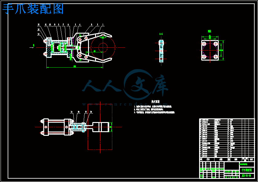
手爪装配图.dwg

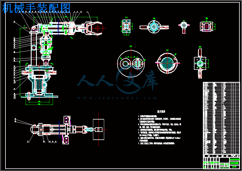
机械手装配图.dwg

气动夹具装配图.dwg

轴承端盖.dwg
摘 要

   针对数控车床设计的一种套类零件自动上下料机构,实现了坯料的抓取、自动定位、夹紧以及工件的回放。该机构主要由自动安装夹具,坯料、工件拾取机械手,动力及控制系统组成。零件的自动定位、夹紧由弹簧涨胎心轴实现,涨胎心轴是以工件的内孔表面定位,由气缸驱动弹性筒夹向外扩涨,实现工件的定位和夹紧的。坯料、工件的拾取、回放是由单臂形式的机械手通过伸缩、旋转以及俯仰等运动实现的,这些运动均由气缸驱动获得。

   本设计中,为实现工件的自动上下料,单臂机械手的运动与涨胎心轴的张合需进行紧密配合。考虑到所夹持工件的实际尺寸、质量等因素,本机构采用气动夹具、电气控制实现了坯料和工件的拾取、安装、回放过程的自动完成。

   本文对气动机械手进行总体方案设计,确定了机械手的坐标形式和自由度。同时,设计了机械手的夹持式手部结构。

关键词: 自动上下料;气动机械手;气动夹具;套类零件  

Abstract

   This paper is aimed at designing a sleeve parts automatic baiting agencies for a CNC lathe.Its function is processing the crawls, automatic positioning and clamping of the workpiece.The automatic baiting agencies mainly consist of the automatic fixture, the manipulator for picking up the workpiece and billets and the drive and control system.Among them,the automatic positioning and clamping of the sets parts is achieved by the axis fetal heart rate rising to the workpiece centering hole.When clamping the workpiece,flexible tube folder can center and clamp the cylindrical hole through the expansion and inflation;blank grasping of the workpiece and the intervals are achieved by the manipulator arm by stretching and rotating.In the issue,it is necessary for the movements of the manipulator arm and the automatical fixture Zhang to require the coordination.Taking into account that the actual workpiece size,the quality and the various features of the driven approach to the system,we decide to adopt the aerodynamic control,using compressed air to achieve the movements of the clamping fixture and manipulator.

Keywords:Automatic baiting;Pneumatic manipulator;Pneumatic fixture;sleeve parts

目 录

摘要I

AbstractII

第1章  概述1

1.1  气动四自由度机械手结构设计的背景与目的1

  1.1.1  数控机床1

1.2   气动四自由度机械手结构设计的意义4

第2章  总体方案设计5

2.1  方案设计概述5

  2.1.1  方案设计5

     明确设计要求5

     功能分析5

     功能原理设计5

  2.1.2  技术设计5

     确定基本技术参数6

     机械结构设计6

  2.2  驱动方式的确定6

  2.2.1  电动机驱动7

  2.2.2  气压驱动7

  2.3  本章小结9

第3章  气缸夹紧设计10

  3.1 夹紧力的确定10

  3.2  夹紧气缸的设计计算10

  3.3  本章小结12

第4章  机械手设计14

4.1  运动分析14

4.2  结构设计16 

  4.2.1  手部设计16

     概述16

     机械式手抓设计16

     夹紧气缸的设计计算17

  4.2.2  臂部设计19

     臂部设计的基本要求19

     手臂直线运动机构20

     手臂伸缩运动气缸的设计计算20

  4.2.3  机身设计22

     概述22

     臂部俯仰运动气缸的设计计算23

     回转运动气动装置的设计计算25

    4.3  本章小结27

结 论28

致 谢29

1.2   气动四自由度机械手结构设计的意义

   该机械手利用压缩空气作为动力源,取之不尽,用之不竭,可以节约能源,气体不易堵塞流动通道,用过后可随时排入,不污染环境,成本较低,维护保养容易气动动作迅速,反应快,气动机械手与气动夹具相互配合工作,能够实现数控车床的自动连续工作,从而提高了加工成本,降低了工人的劳动强度。    第2章  总体方案设计

2.1  方案设计概述

   机械产品的设计过程由三个相互影响的步骤组成,称为方案设计阶段(或称概念设计阶段)、技术设计阶段(或称初步设计阶段)和施工设计阶段(或称详细设计阶段)。

2.1.1  方案设计

   方案设计阶段的主要任务是根据计划任务书,在经调研进一步确定设计要求的基础上,通过创造性思维和试验研究,,克服技术难关,经过分析、综合与技术经济评价,使构思和目标完善化,从而确定出产品的工作原理与总体设计方案。  明确设计要求  

   设计要求主要是功能要求、使用性能要求、工况适应性要求、宜人性要求、外观要求、环境适应性要求、工艺性要求、法规与标准化要求、经济性要求等等。

 功能分析

   技术系统是由构造体系和功能体系构成的。建立构造体系是为了实现功能要求。对技术系统从功能体系入手进行分析,有利于摆脱现有结构的束缚,形成新的更好的方案。功能分析的目标是通过分析,建立对象系统的功能结构,通过局部功能的联系,实现系统的总功能。功能分析过程是设计人员初步酝酿功能原理设计方案的过程。这个过程往往不是一次能够完成的,而是随着设计工作的深入进行不断修改、完善。

 功能原理设计

   此阶段的落脚点是为不同的功能、不同的工作原理、不同的运动规律匹配不同的结构,这就是通常所说的型、数综合,而且通过上述的排列组合,会出现非常多的功能原理解,产生很多的运动方案,这就为优选方案提供了基础。   套类零件自动上下料机构主要由单臂机械手、弹簧涨胎心轴夹具组成,二者均由气动驱动并辅以电气控制。其中,单臂机械手由伸缩气缸、升降气缸和旋转气缸等通过法兰、螺栓联结而成,能够旋转180°进行机床的上下料。弹簧涨胎心轴作为车床夹具,通过夹具体与主轴相连并带动工件回转,它主要由弹性筒夹和心轴组成,通过均匀弹性变形实现定心夹紧。

   本上下料机构采用气动驱动机械手,实现了内径φ30~40mm、外径φ60~80mm、长度150mm套类工件、坯料的拾取、回放等功能;采用弹簧涨胎心轴实现了工件的自动定位、夹紧;通过气动、电气控制系统实现了拾取——送料、定位——夹紧、拾取——回放等过程的自动完成。对相关自动输送料系统的设计有一定的参考价值。

   本自动上下料机构基本满足了所有功能要求,实现了自动化过程,但在其细节处仍存在一些问题:

   (1)上料过程中,机械手将工件送入夹具时,夹具对工件进行精确定位夹紧;

   (2)在不损伤工件的前提下,手爪夹紧工件时,夹紧力的精确控制。

上述问题在设计过程中未得到圆满解决,仍需日后继续解决。

参考文献

[1]  陈奎生. 液压与气压传动[M]. 武汉理工大学出版社,2001.8:3.

[2]  张树森. 机械制造工程学[M]. 东北大学出版社,2001.3:228-258.

[3] 付亚军. 花键轴自动线上下料机械手的设计[J]. 十堰大学学报(自然科学版).1997,(1):36-39.

[4]  梁梅超. 一种数控车床气动自动夹紧送料装置[J]. 机械制造. 2005.8,43(492):67-68.

[5]  朱光力. 三坐标气动机械手气动控制回路设计[J]. 机械设计与制造. 2003.4,(2):61-62.

[6]  高微,杨中平,赵荣飞等. 机械手臂结构优化设计[J]. 机械设计与制造. 2006.1,(1):13-15.

[7] Babu,Valli,Anil Kumaretal.Automatic Modular Fixture Generation in Computer-Aided Process Planning Systems[J].Proceeding of the I MECH E Part C Journal of Mechanical Engineering Science.2005,10:1147-1152.

[8] Amy J.C.Trappey,C.Richard Liu.Automated fixture configuration using projective geometry approach[J].The International Journal of Advanced Manufacturing Technology.1993,8(5):297-304.

[9] S.-H.Lee,T.A.Lasky,S.A.Velinsky.Manipulability-Based Design and Analysis of Hybrid Manipulator for Highway Application[J].Mechanics Based Design of Structures and Machines .2005,33(1):99-118

[10]  李剑玲,贺炜,丁毅等. 一种换刀机械手卡爪夹紧机构的设计[J]. 组合机床与自动化加工技术. 2003,(10):48-49.

[11]  张波,李卫民,尚锐. 多功能上下料用机械手液压系统[J]. 液压与气动. 2002,(8):31-32.

[12]  聂彤. 多机械手气动系统的设计方法[J]. 液压与气动. 2001,(3):25-27.

内容简介:
附录1 数控机床是一种以数字量作为指令信息、形式,通过电子计算机或专用计算机装置控制的机床,是在机电一体化技术的基础上发展起来的一种灵活而高效的自动化机床,在机械行业中得到了日益广泛的应用 数控机床是按照预定程序自动工作的,一般情况下工作过程不需要人工干预,这就消除了操作者认为生产的误差。在设计制造设备主机时,通常采取了许多措施,使数控设备的机械部分达到较高的精度。数控装置的脉冲当量可达0.010.00002mm, 同时,可以通过实现检测反馈修正误差或补偿来获得更高的精度。因此,数控机床可以获得比机床本身精度更高的加工精度。尤其提高了同批零件生产的一致性 ,使产品质量获得稳定的控制。数控机床的工作是按预先编制好的加工程序自动连续完成的,操作者除输入加工程序及相关的操作之外,不需进行繁重的重复手工操作,劳动条件和劳动强度大为改善。数控机床与普通机床相比具有许多优点,其应用范围正在不断扩大,但目前它并不能完全替代普通机床,也还不能以最经济的方式解决机械加工中的所有问题。在实际选用时,一定要充分考虑其技术经济效益。由于数控机床的自动化程度、生产效率都很高,可最大限度地减小操作工人。因此,大批量生产的零件采用数控机床加工,在经济上也是可行的。车床主要是用于车削加工,在机床上一般可以加工各种回转表面,如内外圆柱面、圆锥面、成形回转表面及螺纹表面等。在数控车床上还可以加工高精度的曲面与端面螺纹。用的刀具主要是车刀、各种孔加工工具(钻头、铰刀、镗刀等)及螺纹刀具。车床主要用于加工各种轴类、套筒类和盘类零件上的回转表面。数控车床加工零件的尺寸精度可达IT5IT6,表面粗糙度可达1.6m以下。数控车床的种类很多,各种卧式车床都有数控化的。数控车床主要可分为数控卧式车床、数控立式车床和数控专用车床(数控凸轮车床、数控曲轴车床、数控丝杠车床等);或分为普通数控车床和车削加工中心。现在,数控车床技术还在不断向前发展着。随着数控系统,机床结构和刀具材料的技术发展,数控车床将向高速化发展,进一步提高主轴转速、刀具快速移动以及转位换刀速度;工艺和工序将更加复合化和集中化;数控车床向多主轴、多刀架加工方向发展;为实现长时间无人化全自动操作,数控车床向全自动化方向发展;机床的加工精度向更高方向发展。同时,数控车床也向简易型发展。 随着工业自动化程度的提高,工业现场的很多重体力劳动必将有机器代替,这一方面可以减轻工人的劳动强度,另一方面可以大大提高劳动生产率。随着机械制造业的日益发展和数控车床的普及使用,工件的装夹往往成为制约提高加工效率的主要原因,而普通车床常用的夹紧送料方式是采用手工送料,利用装在机床主轴法兰上的三爪卡盘或四爪卡盘进行夹紧工件,装夹时间较长,工人的劳动强度大。对于数控车床而言,人工装夹时间往往比加工时间还长,为此,在数控车床上曾开发出液压或电机夹紧送料装置。液压夹紧装置虽然体积小,但必须每台车床配备一套液压站,所以其成本较高,且送料机构采用重物提拉方法,结构大,占用地方多,另外液压站使用的介质为液压油,维护保养时易污染环境等。电机夹紧装置的体积较液压夹紧装置稍微大些,较经济,但一般只有夹紧装置而只有送料装置,使数控车床无法实现自动连续工作,从而降低了数控车床的加工效率。套类零件自动上下料机构主要包括自动安装夹具,坯料、工件拾取机械手,动力及控制系统。在数控车床加工过程中,该机构用于实现坯料的抓取、自动定位夹紧以及工件的回放等功能,可以实现数控车床的自动连续工作,操作简便,大幅度提高了工作效率和加工的自动化程度。附录2Nc machine tool is a kind of digital quantity as instruction information, form, by computer or dedicated computer device control machine tool, is developed on the basis of the electromechanical integration technology of a flexible and efficient automated machine tools, are widely used in machinery industryNc machine tool is in accordance with the scheduled program automatic work, working process normally does not need manual intervention, this eliminates the error of the operator that production. In equipment design and manufacture of the host, usually taken many measures, make the mechanical parts to achieve high precision of the numerical control equipment. Numerical control device of pulse equivalent to 0.01-0.00002 mm, at the same time, can realize test feedback error correction or compensation to obtain higher precision. Therefore, numerical control machine tool can achieve higher precision than the machine itself the machining accuracy. Especially enhances the consistency of production, with the number of parts which controls the product quality stability.CNC machine work is a good processing program is done automatically and continuously advance, in addition to the operator input processing procedures and related operations, without heavy on repeat manual operation, has improved working conditions and labor intensity.Nc machine tool has a number of advantages when compared with the general machine tools, its application scope is expanding constantly, but it is not entirely replace the ordinary machine tool, is not the most economical way to solve all the problems in machining. In actual use, must give full consideration to the technical and economic benefits.As a result of the nc machine tool, the production efficiency is very high degree of automation, can minimize operation workers. Therefore, mass production parts adopt numerical control machine, is also feasible in economy.The lathe is mainly used for turning processing, generally in the machine tool processing can be all kinds of rotary surface, such as internal and external rotary cylinder, cone surface, forming surface and thread surface, etc. On the nc lathe can also processing precision of curved surface and end thread. With a cutting tool is mainly lathe tool, all kinds of machining tools (drill, reamer, boring cutter, etc.) and thread cutting tools. Lathe is mainly used for processing various shaft, sleeve and the rotary surface of the plate parts. Numerical control lathe processing parts size accuracy can reach IT5 IT6, surface roughness of 1.6 microns.Many different kinds of CNC lathe, all kinds of horizontal lathe of numerical control. CNC lathe main can be divided into nc horizontal lathe, nc vertical lathe and special numerical control lathe, numerical control CAM lathe, CNC crankshaft lathe, CNC lathe ball screws, etc.); Or is divided into general CNC lathes and turning center.Now, also in the continuous development of the numerical control lathe technology. With numerical control system, the machine tool structure and tool material technology, numerical control lathe to the high speed development, further improve the spindle speed, cutting tool speed fast moving and transposition in the edge of the sword; Composite technology and the process will be more and centralization; Numerical control lathe to develop in the direction of the spindle, tool post processing. To realize unmanned automatic operation for a long time, the numerical control lathe to develop in the direction of fully automated; The machining precision of machine tools to a higher direction. At the same time, numerical control lathe to simple type development.With the improvement of industrial automation, industrial site of many heavy physical labor is sure to have a machine to replace, this can reduce the labor intensity of workers, on the one hand, on the other hand can greatly improve the labor productivity. With the development of mechanical manufacturing and the popularity of numerical control lathe, workpiece clamping, often become the main reason for the improvement of machining efficiency, common and ordinary lathe clamping feeding way is to use the manual feeding, use of mounted on the spindle flange three jaw chuck or four jaw chuck clamping workpiece, the clamping time is longer, the workers labor intensity. For CNC lathe tooling clip than processing time is long, therefore, on the CNC lathe has developed the hydraulic clamping feeding device or motor. Hydraulic clamping device is small in size, but must each lathe is equipped with a set of hydraulic station, so the cost is higher, and weight lifting method is used for the conveying mechanism, structure, take up the place, also use the medium for hydraulic oil hydraulic station, when the maintenance is easy to pollute the environment, etc. Motor clamping device of the hydraulic clamping device of a slightly larger size, more economic, but usually only only feeding device, clamping device and make the CNC lathe is unable to achieve automatic continuous working, which reduces the efficiency of nc lathe machining.Set of parts mainly includes automatic installation jig automatic up-down material mechanism, billet, workpiece picking manipulator, power and control systems. In the process of numerical control lathe processing, the agency is implemented by scraping blank, automatic positioning, clamping and artifacts of playback, and other functions, can realize automatic CNC lathe work continuously, simple operation, greatly improved the working efficiency and processing automation.working process normally does not need manual intervention, this eliminates the error of the operator that production. In equipment design and manufacture of the host, usually taken many measures, make the mechanical parts to achieve high precision of the numerical control equipment. Numerical control device of pulse equivalent to 0.01-0.00002 mm, at the same time, can realize test feedback error correction or compensation to obtain higher precision. with the general machine tools, its application scope is expanding constantly, but it is not entirely replace the ordinary machine tool, is not the most economical way to solve all the problems in machining.generally in the machine tool processing can be all kinds of rotary surface, such as internal and external rotary cylinder, cone surface, forming surface and thread surface, etc. On the nc lathe can also processing precision of curved surface and end thread. With a cutting tool is mainly lathe tool, all kinds of machining tools (drill, reamer, boring cutter, etc.) and thread cutting tools.numerical control lathe to the high speed development, further improve the spindle speed, cutting tool speed fa
温馨提示:
1: 本站所有资源如无特殊说明,都需要本地电脑安装OFFICE2007和PDF阅读器。图纸软件为CAD,CAXA,PROE,UG,SolidWorks等.压缩文件请下载最新的WinRAR软件解压。
2: 本站的文档不包含任何第三方提供的附件图纸等,如果需要附件,请联系上传者。文件的所有权益归上传用户所有。
3.本站RAR压缩包中若带图纸,网页内容里面会有图纸预览,若没有图纸预览就没有图纸。
4. 未经权益所有人同意不得将文件中的内容挪作商业或盈利用途。
5. 人人文库网仅提供信息存储空间,仅对用户上传内容的表现方式做保护处理,对用户上传分享的文档内容本身不做任何修改或编辑,并不能对任何下载内容负责。
6. 下载文件中如有侵权或不适当内容,请与我们联系,我们立即纠正。
7. 本站不保证下载资源的准确性、安全性和完整性, 同时也不承担用户因使用这些下载资源对自己和他人造成任何形式的伤害或损失。
提示  人人文库网所有资源均是用户自行上传分享,仅供网友学习交流,未经上传用户书面授权,请勿作他用。
关于本文
本文标题:四自由度气动机械手设计【5张CAD图纸】【优秀】
链接地址:https://www.renrendoc.com/p-396440.html

官方联系方式

2:不支持迅雷下载,请使用浏览器下载   
3:不支持QQ浏览器下载,请用其他浏览器   
4:下载后的文档和图纸-无水印   
5:文档经过压缩,下载后原文更清晰   
关于我们 - 网站声明 - 网站地图 - 资源地图 - 友情链接 - 网站客服 - 联系我们

网站客服QQ:2881952447     

copyright@ 2020-2025  renrendoc.com 人人文库版权所有   联系电话:400-852-1180

备案号:蜀ICP备2022000484号-2       经营许可证: 川B2-20220663       公网安备川公网安备: 51019002004831号

本站为文档C2C交易模式,即用户上传的文档直接被用户下载,本站只是中间服务平台,本站所有文档下载所得的收益归上传人(含作者)所有。人人文库网仅提供信息存储空间,仅对用户上传内容的表现方式做保护处理,对上载内容本身不做任何修改或编辑。若文档所含内容侵犯了您的版权或隐私,请立即通知人人文库网,我们立即给予删除!