新建 Microsoft Word 文档 (2).docx

基于Solidworks的抓物机器车机构设计及运动仿真【三维SW】【20张CAD图纸+PPT答辩稿+论文】

收藏

资源目录
跳过导航链接。
基于Solidworks的抓物机器车机构设计及运动仿真【三维SW】【全套CAD图纸+WORD毕业论文】【答辩通过】.rar
连杆盘.DWG---(点击预览)
连杆.DWG---(点击预览)
轴啊.DWG---(点击预览)
转臂.DWG---(点击预览)
设计说明书.docx---(点击预览)
装配体1.DWG---(点击预览)
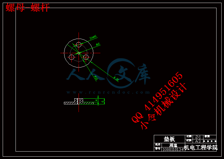
螺母-螺杆.DWG---(点击预览)
螺杆.DWG---(点击预览)
答辩PPT.pptx---(点击预览)
爪子.DWG---(点击预览)
毕设进度表.doc---(点击预览)
支板2.DWG---(点击预览)
支板1.DWG---(点击预览)
开题报告.doc---(点击预览)
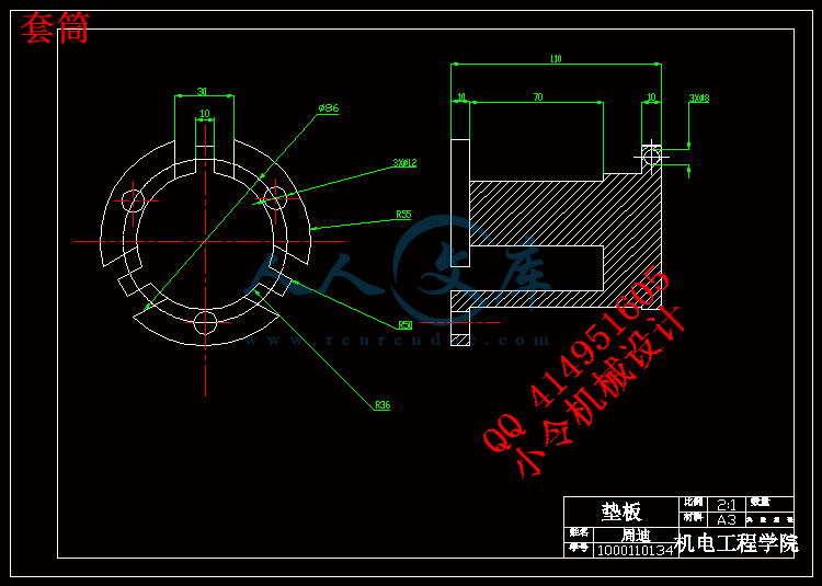
套筒.DWG---(点击预览)
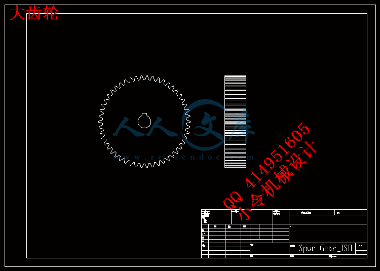
大齿轮.DWG---(点击预览)
固定架.DWG---(点击预览)
任务书.doc---(点击预览)
中间板.DWG---(点击预览)
中期检查表.doc---(点击预览)
丝杆螺母.DWG---(点击预览)
丝杆.DWG---(点击预览)
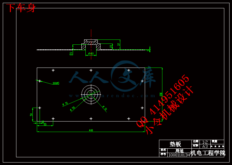
下车身.DWG---(点击预览)
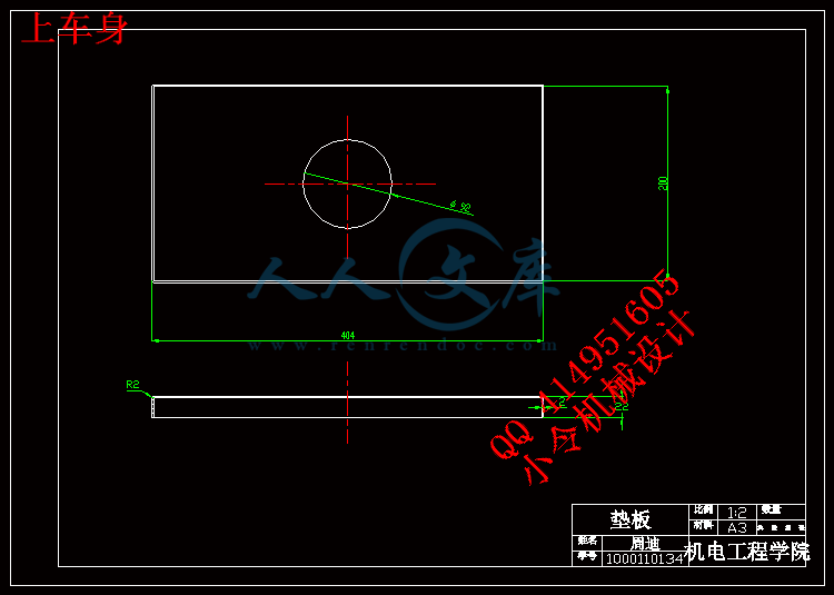
上车身.DWG---(点击预览)
A3小图汇总.dwg---(点击预览)
a3 小图汇总.dwg---(点击预览)
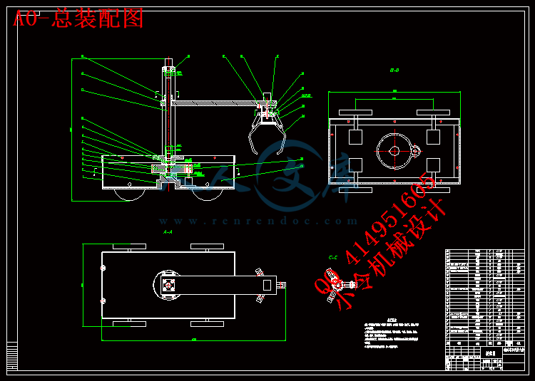
A0-总装配图.dwg---(点击预览)
三维SW
A3.dxf
plot.log
上车身.SLDPRT
下车身.SLDPRT
丝杆.SLDPRT
丝杆螺母.SLDPRT
中间板.SLDPRT
固定架.SLDPRT
地面.SLDPRT
套筒.SLDPRT
支板1.SLDPRT
支板2.SLDPRT
板.SLDPRT
板2.SLDPRT
爪子.SLDPRT
物体.SLDPRT
螺杆.SLDPRT
螺母-螺杆.SLDPRT
螺钉3.SLDPRT
装配体1.IGS
装配体1.SLDASM
转臂.SLDPRT
轮子.SLDPRT
轴啊.SLDPRT
连杆.SLDPRT
连杆盘.SLDPRT
外文翻译
视频
毕设.pdf---(点击预览)
爆炸.avi
爆炸1.avi
爆炸2.avi
装配1.avi
装配体1.avi
装配体2.avi
压缩包内文档预览:
预览图 预览图 预览图 预览图 预览图 预览图 预览图 预览图 预览图
编号:402473    类型:共享资源    大小:15.66MB    格式:RAR    上传时间:2015-01-31 上传人:好资料QQ****51605 IP属地:江苏
50
积分
关 键 词:
基于 solidworks 机器 机构 设计 运动 仿真 三维 sw 全套 cad 图纸 word 毕业论文 答辩 通过
资源描述:

【温馨提示】 购买原稿文件请充值后自助下载。

[全部文件] 那张截图中的文件为本资料所有内容,下载后即可获得。


预览截图请勿抄袭,原稿文件完整清晰,无水印,可编辑。

有疑问可以咨询QQ:414951605或1304139763

摘  要

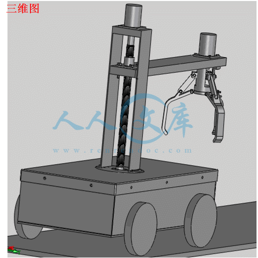
很多地方是我们人类没法进去的,因为其中的一些东西已经对我们造成了生命的威胁,但我们又有必须进去的理由。在这种场合下,机械就能为我们解决这些问题,因为它可以代替我们进行一些危险操作,用来取代人力来工作。我们设计的抓物机器车是在机械化,自动化生产过程中发展起来的一种将机械手和搬运车联系为一体的产品。使其能抓物运动,可以在地形复杂或恶劣、危险的环境里替人完成物体的搬运或者障碍的清除等工作。
抓物机器车的设计主要是通过无线通信来控制小车的前进、后退或者转弯,并由螺杆转动,带动螺杆上的螺母上下移动,再通过连杆结构实现抓爪的闭合,从而实现抓物动作。丝杆竖直放置,转臂固定在丝杆螺母上,步进电机带动丝杆旋转,螺母会上下移动,转臂也会上下移动,也就是机械手上下移动,满足了机械手降下抓物,升高移动物体的情况。机械手的转动,在由齿轮带动固定丝杆的中间件转动而实现的。
关键词:机器车;抓物;丝杆

Abstract

Many things that we humans can not go , because some of these things have been a threat to our life , but the reason we have to go in there . In this case , our machinery will be able to solve these problems. Because it can replace us doing some dangerous operation , to replace manpower to work. Because it can replace us some dangerous operation, to replace manpower to work. We have designed the Grasping machine car that developed in the mechanization and automation of the production process and the robot van combined into one product. So that it can catch things exercise can help people complete the removal of an object or obstacle clearance work in complex terrain or harsh, dangerous environment.
Grasping machine car designed primarily controlled by a wireless communication car forward, backward, or turn. by the screw rotates, driven to move up and down the screw on the nut, and then realize gripper closure through the link structure to realize grasping objects actions . Screw placed vertically, and the arm is fixed on  screw nut, stepper motor driven rotary screw, nut meeting next move, the arm will move up and down, which is under the robot moves down to meet the robot grasping objects, elevated movement of the object. Turn the robot, driven by fixed-gear screw rotation middleware
implementation.
Key words: machine car; grasping objects; screw


目    录
引言 1
1  设计方案 2
1.1 设计内容 2
1.2 设计目的 2
1.3 方案的选择 2
2  机械手的设计 3
2.1 抓手结构的设计 3
2.2 爪片的设计 5
2.3 螺杆的设计 7
2.3.1确定螺纹中径 8
2.3.2螺杆的强度计算 9
2.3.3螺母螺纹牙的强度计算 9
2.4 连杆盘的设计 10
2.5 套筒的设计 11
2.5.1套筒的尺寸 11
2.5.2螺栓的选择 11
2.5.3螺纹连接的防松 13
3  转臂的设计 13
3.1 受力分析 13
3.2 转臂的尺寸计算 14
3.3 螺栓的设计 15
3.3.1螺栓组结构设计 15
3.3.2螺栓受力分析 15
4  滑动丝杆的设计 16
4.1 螺纹牙型的选择 16
4.2 螺距选择 16
4.3 丝杆直径的确定 16
4.4 螺杆的强度计算 17
4.5 螺母螺纹牙的强度计算 17
4.6 丝杆的长度 18
4.7 丝杆螺母的传动形式 18
4.8 丝杆的固定 19
4.9 轴承的选择 19
4.10 固定板的设计 21
4.10.1固定板的结构 22
4.10.2固定架的固定 22
5  转盘的设计 23
5.1 中间板的设计 23
5.2 键的选择 25
5.3 齿轮的设计 25
5.3.1选定齿轮类型,精度等级,材料及模数 25
5.3.2按齿面接触疲劳强度设计 26
5.3.3按齿根弯曲疲劳强度设计 27
5.3.4几何尺寸计算 27
5.4 轴的设计 28
6  车身的设计 30
6.1 上车身的设计 30
6.2 下车身的设计 31
6.3 支板的设计 35
6.3.1支板的结构 35
6.3.2尺寸计算 35
6.3.3支板的连接 36
6.3.4轮子孔的设计 36
7  solidworks的建模和仿真 37
8  总结 38
谢  辞 39
参考文献 40


引言
随着社会的进步,社会的分工也越来越细,特别是在现代化的生产中,有的人每天就只能做着同一件事,或者是拧同个部位的某个螺母,或者是接着同一个地方的线头,就像电影《摩登时代》中所演的,由于老是做同一个动作,身体相同的部位得不到休息,于是开始产生了各种职业病。于是人们强烈的希望能有什么东西能代替自己工作而自己不用那么的难受。于是机器人就被发明了出来,并替人完成那些很枯燥、单调、危险的工作。而且,机器人的发明大大的提高了工作效率,提高了工业的发展,为更多的人提供了机会。
机器人的出现,使人们摆脱了那些繁琐、危险的工作。一般的,在有危险,对人体有害的场合,你总能看到他们的身影。如喷漆行业,油漆发出的气味很难闻,那是有毒气体,闻多了会对人体造成难以想象的伤害;还有电焊的场合也是对人眼睛的伤害也很大,也是有了专门用来焊接的机器人。这样的地方很多,在工业里已经屡见不鲜了。特别是在汽车和工程机械行业里,喷漆和焊接那是必不可少的。也正是这些工作对汽车行业的不可或缺,近几年来,国内生产的工业机器人大多是用于服务汽车行业的,也正因为这样,汽车工业的发展也推动了机器人的增长。
在一些对灰尘要求很严的重要场合或者实验室中,一旦灰尘的量超过了标准,就会有废品的出现。例如要在 10级洁净室中制造的电脑重要器件。按国际标准,10级洁净室就是要在一立方英尺内不得出现超过10个以上的直径大于0.5微米的尘埃。100级洁净室就是在一立方英尺内不得出现100个同样大小的尘埃。可就是想进入100级洁净室,工作人员也要换上特制的装备才可以进去,而且,在进去之前的5个小时都不可以使用化妆品或者吸烟等,这条件可见很难做到了。所以10级洁净室也只能由机器来完成了,想进去,条件太苛刻了。
而有些场合,由于被环境的限制,如有放射性物质,被有害气体包围等,我们很难进去,也没法找里面的东西出来研究。于是特制的抓物机器车就很有必要设计出来。
这次设计是基于三维软件Solidworks设计的。该软件的功能很强大,组件也很多。 Solidworks是现在最主流的三维CAD解决方案,因为他具有了功能强大、易学易用、技术创新等特点。 而且SolidWorks可以提供不同的设计方案、减少了设计过程中的错误以便提高产品质量。对工程师和设计者来说,SolidWorks 不仅提供如此强大的功能,操作更是简单方便、易学易用。


1 设计方案
1.1 设计内容
因为是要进行比较精密的抓取物体,所以采用无线通信技术实现对机器车的控制。通过无线接通电机,电机驱动轮子来实现小车的前进、后退与转向。而在小车的上面则是抓物机械手的部件。要实现机械手的上下移动还有一定范围的转动,还有爪片的自由张合。
1.2 设计目的
(1)可以在危险的,无人可进入的地方抓住物体并且移动物体,便于实验和研究。
(2)由于抓物机器车使用无线通信技术控制,其动作准确,操作简单,因此可以提高稳定性能。
1.3 方案的选择
由于小车的移动都要很精确,所以只考虑了步进电机和伺服电机。步进电机的速率是由驱动器信号输入的脉冲数量和频率来控制的。但不适合在长时间和同方向的场合使用,这样容易烧坏电机。而伺服电机与步进电机相比,在控制方式上很相似都是用脉冲串和方向信号,但价格相对来说较高。在性能满足的情况下,考虑经济方面,我们采用了步进电机。
对于机械手的上下移动,可以想到的有液压、气动还有丝杆。考虑液压和气动都比较的便宜,但考虑到精确度,能采用的也只有丝杆了。对于爪片的自由张合,气动便宜实用,但由于在前面都没用到,在这里用的话还得设计气动装置,麻烦而且也不太实际,因此我们采用了步进电机。

2 机械手的设计
由于设计的抓物车一般是在危险的地方工作,那地方可能是一些夹缝什么的,因此我们设计的小车都比较的小。设小车的尺寸为400*200*100mm,而抓取的物体最重为6KG。
2.1 抓手结构的设计
设抓盘的直径为50mm,爪子的开口角度为120度,抓爪可转动30度。采用的是四杆机构来实现爪子的自由张合。结构如图所示:

图2-1 四杆结构简图
其中L1是连杆盘与抓盘的距离,L2是爪子上两个圆柱销之间的距离,L3是连杆与爪子的距离,L4是连杆。
如图,L2、L3、L4为定长,而L1随着连杆盘的移动而改变,当连杆盘向上移动时,L1会变大,那时,连杆L4通过L3拉着L2向上转动,那时爪子张开:相反,当连杆盘向下移动时,连杆会压爪子向下转动,即爪子会抓紧物体。
受力分析:

内容简介:
编号: 毕业设计(论文)外文翻译(原文)院 (系): 机电工程学院 专 业: 机械设计制造及其自动化 学生姓名: 韦子亮 学 号: 1000110130 指导教师单位: 桂林电子科技大学 姓 名: 彭晓楠 职 称: 副教授 2014年 5 月 23 日Design of Lightweight Lead Screw Actuators for Wearable Robotic ApplicationsJournal of Mechanical DesignKevin W. Hollander Thomas G. SugarA wearable robot is a controlled and actuated device that is in direct contact with its user. As such, the implied requirements of this device are that it must be portable, lightweight, and most importantly safe. To achieve these goals, The design of the standard lead screw does not normally perform well in any of these categories. The typical lead screw has low pitch angles and large radii, thereby yielding low mechanical efficiencies and heavy weight. However, using the design procedure outlined in this text, both efficiency and weight are improved; thus yielding a lead screw system with performances that rival human muscle. The result of an example problem reveals a feasible lead screw design that has a power to weight ratio of 277 W/kg, approaching that of the dc motor driving it, at 312 W/kg, as well as a mechanical efficiency of 0.74, and a maximum strength to weight ratio of 11.3 kN/kg 。 1 Introduction One in five persons in the United States live with some form of disability, with 61% of those suffering from either a sensory or physical disability.As an example, within the elderly population,8% to 19% are affected by gait disorders . Many disabled individuals could benefit from some form of robotic intervention. A wearable robot is a computer controlled and actuated device that is in direct contact with its user. The purpose of such a device is the performance/strength enhancement of the wearer. It can be used in training, in therapy, or simply as a device to assist in functional daily living. The implication of the term “wearable” isthat the robot must be portable, lightweight, and most importantly safe. In contrast, a factory floor robot is none of these things, so the simple adaptation of existing technology is not possible. The standard approach to wearable robot design suffers from three major limitations;1 Low battery power density;2 motors with low “strength to weight” ratios;3 weight and safety of a mechanical transmission system. The goal of this work is to review the design process of a lead screw actuator; the result of which will demonstrate significant improvements over the limitations described in item number 3, i.e., the weight and safety of the mechanical transmission system.2 BackgroundInterest in the area of wearable robotics has grown over the last decade. The recent surge of interest can be attributed to advancements in electronic miniaturization, microprocessor capabilities, and wireless technology proliferation. The feasibility of a portable computer controlled strength enhancing device is closer to reality However, aside from the availability of portable computation platforms, issues of the physical mechanism must still be addressed. The main issues in any wearable robot development are power, weight, and safety. How much power is available to do mechanical work? How much additional weight does the robotic device add to the person? And, how can this power be transferred and still maintain safety? The safe interaction between the wearer and theactuated robot has to be the primary concern in a wearable robot design.The purpose of a wearable robotic system is to offset the effort or energy of the operator by some amount of energy from a storage device, i.e., battery, fuel cell, and air tank. The sharing of the work load between the operator and the robot is heavily influenced by actuator efficiencies and the overall system weight. The additional weight that the robot adds to the user, in many cases, can increase the total amount of work required to accomplish a given task. This means that the robot not only has to augment the operators abilities, but must also compensate for its own additional weight.2.1 Actuator Comparisons. Human skeletal muscle is the “gold” standard by which many robotic actuators are compared. Known for their good “power to weight” ratios and excellent force production capabilities, skeletal muscle performance is what most actuator designers would like to match. In order to match the performance capabilities of skeletal muscle, it is important to know some of its measures. Unfortunately, common throughout biological literature is a wide variation of measured muscle properties. Although reported values have a wide variance, these values can still give a sense of scale in which biological materials behave. Data tabulated and estimated from several sources were used to describe the attributes of human muscle performance, and the result of which can be seen in Table 1.Table1:Actuator comparison: Compares various actuator types by mechanical efficiency, power to weight ratio, “corrected”power to weight ratio, and strength to weight ratio Measuresallows the direct comparisons to be made based upon utilization of available energy. However, both of these parameters need to be examined in the development of a wearable robotic actuator. Consider that if all actuators were to operate at 100% efficiency, then the entire group could be compared directly by their respective power to weight ratios. However, if only the power stated in the power to weight ratio were supplied to each actuator, then because of their respective efficiency, only a fraction of that power would be yielded as output. Therefore, to appropriately compare the above described actuators, their corrected power to weight(c) ratios must be computed (1)where is the mechanical efficiency and Pwt is the original power to weight ratio. The results of this calculation for various kinds of actuators can be seen in Table 1.Values in Table 1 were obtained either by referenced literature or estimations based upon that literature. The values for the dc motor are for the Maxon RE40 motor. The values for the + gearbox combination were also found in the Maxon 2004 catalog. values from an electric Series Elastic Actuator were used to estimate these parameters. However, a similiarly sized lead screw system will likely have a better strength to weight ratio, due to its ability to carry higher loads and its nut is of lower weight. For the McKibben style air muscles, a variety of literature was found describing its relevant measures.Immediately evident in this comparison is that the corrected power to weight, cP, values of the dc motor, the air muscle and human skeletal muscle are all similarly matched. However, once additional hardware is added to the dc motor, its performance decreases significantly. If one could create a mechanical transmission system that did not significantly alter the weight of the dc motor based actuator, then performances very near that of human skeletal muscle could be achieved.3 Lead Screw Design。Seen above, the performance of a typical lead screw system is limited when compared to other wearable robotic actuator concepts. The primary reason for its low performance is poor mechanical efficiency. The coefficient of friction in a standard lead screw system is approximately =0.36., metal on metal, better results are possible if lubrication is used.In contrast, the typical ball screw system has very good mechanical efficiency. The rolling contact of the ball bearings keeps the frictional effects on this system to an absolute minimum. However, even with its improved efficiencies, the cP value for the ball screw actuator is still well below that of skeletal muscle, due directly to the considerable weight of the ball screw system. To improve the cP performance of a ball screw, a significantreduction of weight must be achieved.Journal of Mechanical Design Fig. 1 Lead screw geometry; as drawn, pitch p and lead lare equivalent in a single helix screw The basic mathematics surrounding the design of a lead screw can also apply to a ball screw system. The primary difference between these two mechanical transmissions is their coefficient of friction. In the following section, an exploration of the design parameters that influence weight and mechanical efficiency of a lead screw will be considered and thus improvements to its ccan be made.3.1 Lead Screw Geometry.Shown in Fig. 1 is the basic geometry of a common lead screw. The key parameter of a lead screw is the lead, l, which is dependent on screw radius, r, and lead angle. The lead, l, is the amount of displacement achieved for each revolution of the screw. A high precision screw has a very short or fine lead. The right triangle in Fig. 1 shows the unwrapped geometry of a single revolution of a screw. The lead angle , represents the incline or slope of the screw thread. The base of the triangle is the circumference of the screw shaft, the right leg of the triangle is its lead, and the hypotenuse representsthe path length of the helical thread. Also seen on the right triangle are the forces present on a screw that is lifting a load. The force of the load is shown as Fw, the force resulting from the torque on the screw is F, the normal reaction force on the thread of the screw isN, and the frictional force is N. From this diagram, the following equation for a lifting torque can be derived (2) 3.2 Alpha Versus R.Considering, again, the geometry of a lead screw in Fig. 1, it can be shown that leadl, is described both by screw radiusr, and lead angle. The relationship between these variables is given in (3) (4)The meaning of Eq(4)is that both r, screw radius, and, lead angle, are necessary to create a screw lead, l. This means that there exists a continuous relationship between r and . Although this continuous relationship exists, most screw systems are designed with very small lead angles. A review of the preferred ACME screw sizes reveal that although the individual diameters vary, the lead angles are all less than 3.From Eq(4).it is shown that for any screw lead desired, a variety of radii could be used. The significance of this is that as screw radius, r, shrinks, the weight of the screw shrinks by a factor.r2 Thus, to compensate for small screw radii, a larger value of lead angle , must be considered.Fig. 2 Mechanical efficiency of lead screw systems: Shaded part of the graph is the typical design region for the majority of lead screws. is small, radius is large, weight is large, and efficiencies are lower. Designs in the unshaded region of the graph, where is large, implies smaller radii, lower weight, and higher efficiencies. 3.3 Efficiency Versus Alpha. For a wearable robot design, not only is the weight of a lead screw actuator an important issue, but the efficiency of an actuator is also key. As mentioned before, a decrease in screw radius can achieve significant reductions in actuator weight. However, while the screw radius is reduced, the lead angle, must be increased to maintain a constant lead. When looking at Eq(2). it is seen that the torque required to lift a load, Fw, is dependent upon both lead angle, as well as the coefficient of friction。Relating the efficiency of a screw to both lead angle and coefficient of friction, Figure 2 shows the impact on both coefficient of friction, and lead angle, on the efficiency of a lead screw system (5)Each line in Fig. 2 is based upon a different value of the coefficient of friction. Several common engineering materials are given as examples to give the reader a sense of what effect different materials or coatings could have on the efficiency of a lead screw system. This figure shows that as the lead angle increases, so does the mechanical efficiency; or at least until a peak value is reached.Ideally, it would be advantageous to pick the angle, based upon maximum efficiency. A lead screw system operating at peak efficiency minimizes the input torque requirements to lift the load Fw. The angle at which peak efficiency occurs can be determined by taking the derivative of efficiency with respect to angle, the result of which can be seen in (6)Although a high lead angle can lead to a high efficiency, it can also lead to a system that is “back-drivable”. A back-driveable system is one in which the load, Fw, can cause a rotation of the screw without the assistance of applied torque, thus allowing the load, Fw, to self-lower. A back-driveable lead screw is a bad idea for a car jack, but is desirable in a wearable robot. For the lead angles in which back-drive will occur (7)Lead angle and coefficient of friction are all that influence this condition, regardless of how high the load force becomes. Fora very low coefficient of friction system, such as a ball screw,back-drive is an inevitable consequence.4 Practical ConsiderationsIdeally, as shown in the previous text, it would be desirable to reduce our screw radius, r, to an almost microscopic scale. However, this is not a practical solution, neither from a design nor manufacturing perspective. Although small screw diameters and high lead angles are desired from the perspective of weight and efficiency, they may not allow the designer to meet the strength demands of the physical system. Issues, such as axial yielding,compression buckling, and mechanism bind, need to be considered as well. Consider that a single ultrathin screw may be lightweight, although it may not be strong enough to carry the load required by the system. A single or several screws can be used, but must be sized large enough to handle the load placed upon it. As a note,there is no weight advantage to using several small screws to carry a large load, as the computation for both weight and stress are driven by a cross-sectional area of the screw. However, using several small screws to carry the load can allow the continued use of high lead angles and thus operate with high efficiencies, even in the presence of high loads. By pushing the limits of raw material properties of the lead screw, high axial loading can be achieved. This approach works better for a tensional system than it does for a compression bearing system. When considering the compressive loading of a long slender screw, Euler buckling must be addressed . Similar to that of the McKibben actuators or even human muscles, a lead screw actuator could be designed to bear a tensional load only, thus eliminating the consideration of buckling altogether. Creating a tension-only actuation system in a wearable robot does not necessarily mean that an antagonistic pair is required. In fact, for an assistance robot, a disabled person may only have muscle weakness in a single actuated direction and, therefore, a single tensional actuator would be all that is required to aid that person.。For those designers who would push the limits of the screw radius and thus lead angle to beyond that of maximum efficiency, the presence of friction limits just how far the angle can be inclined. The physical interpretation of this is that the system willbind or lock. This can be seen by evaluating Eq.(2). An evaluation of the denominator in Eq.(2). yields the following relation。 (8) In addition to the practical considerations listed here, there exists many other issues that could be detailed. Examples of which may include torsional stiffness/yielding or even heat dissipation. Each of these factors are important and worthy of consideration, however, the purpose of this exercise is to demonstrate an alternativeto the typical approaches of designing or selecting screw systems. The benefits of this alternative approach are directly applicable to the design issues of a wearable robotic system.5 Example Problem To demonstrate a crude design exercise, consider the peak ankle joint torque during gait of an able-bodied or normal individual that weighs 80 kg and walks at 0.8 Hz stepping frequency. The peak ankle torque during gait is approximately 100 Nm. This peak occurs at roughly 45% of the gait cycle, A gait cycle is defined by the heel strike of a foot to the next heel strike of the same foot. Toe off is the point in which the weight of the individual has transferred to the opposite leg and the initiation of swing begins. The conclusion of the swing phase of gait places the foot back into a heel strike position again and then the next gait cycle can begin.As an example, let us consider building a lead screw actuator for ankle gait assistance. For our problem, let us assume the levelTable 2: Example problem actuator comparison: Compares lead screw designs I and II to human muscle in terms of mechanical efficiency, power to weight ratio, corrected power to weight ratio and strength to weight ratio, measures of assistance to be at 30% and that the actuator acts with a 12 cm moment arm to the ankle joint. These values can be changed but, based upon personal experience, are reasonable in their scale. Using these values and parameters available for a chosen Maxon motor, the RE40, a range of lead lengths for this example solution has been determined; the range of possible screw leads areExample Problem Results. Two lead screw designs were generated to solve this problem. The first design, lead screw I, is a design solved for maximum efficiency. Assuming a lead of 2 mm and a =0.05, yields an efficiency of 0.9 for the screw at =43.5 and a radius of 0.34 mm. With such a small radius, multiple screws are needed to hold the load. Even so, estimates for the actuator power to weight are 280 W/kg. Power to weight has been determined by dividing the peak power required in our example by the weight of the motor and estimated transmission system. From our previous work, the weight of the accessory components was scaled proportionally to the reduced weight of the screw and nut.The second design, lead screw II, uses dimensions available from a commercial vendor. The screw is estimated to have an =13.6 and an efficiency of 0.82. Even with these larger dimensions, the actuators power to weight ratio of 277 W/kg =0.74 is expected. The results of this example problem have been tabulated for the purpose of comparison. Table 2 shows the numerical results of both example lead screw designs. These values are compared to the previous values tabulated for a dc motor alone, and the estimated values for human skeletal muscle. The strength to weight properties calculated for these examples is based upon the peak force required by our example.6 DiscussionIn the analysis of the maximum efficiency solution, lead screw design I, it was shown that a single small radii screw will not always handle the loads required of it. However, a bundle of screws operating in parallel can perform that task with the same high efficiency. Although a 0.34 mm radius screw would not be easily manufactured using typical techniques, it is possible that this kind of approach i.e., use multiple screws to maintain high efficiency could be useful for a MEMs scaled device. One could imagine a compact “force pack” built up from many high efficiency small diameter screws. Without going to the extremes in efficiency for a particular screw design, it was shown that for lead screw design II, a feasible solution exists for our example problem of ankle gait. Corrected power to weight values were obtained that are very close to those discussed for human muscle. Using a similar approach, a ball screw mechanism could benefit in performance, as well. The general approach to creating back-driveable, low weight, and high efficiency screw system can make a dc motor-based actuator a competiti
温馨提示:
1: 本站所有资源如无特殊说明,都需要本地电脑安装OFFICE2007和PDF阅读器。图纸软件为CAD,CAXA,PROE,UG,SolidWorks等.压缩文件请下载最新的WinRAR软件解压。
2: 本站的文档不包含任何第三方提供的附件图纸等,如果需要附件,请联系上传者。文件的所有权益归上传用户所有。
3.本站RAR压缩包中若带图纸,网页内容里面会有图纸预览,若没有图纸预览就没有图纸。
4. 未经权益所有人同意不得将文件中的内容挪作商业或盈利用途。
5. 人人文库网仅提供信息存储空间,仅对用户上传内容的表现方式做保护处理,对用户上传分享的文档内容本身不做任何修改或编辑,并不能对任何下载内容负责。
6. 下载文件中如有侵权或不适当内容,请与我们联系,我们立即纠正。
7. 本站不保证下载资源的准确性、安全性和完整性, 同时也不承担用户因使用这些下载资源对自己和他人造成任何形式的伤害或损失。
提示  人人文库网所有资源均是用户自行上传分享,仅供网友学习交流,未经上传用户书面授权,请勿作他用。
关于本文
本文标题:基于Solidworks的抓物机器车机构设计及运动仿真【三维SW】【20张CAD图纸+PPT答辩稿+论文】
链接地址:https://www.renrendoc.com/p-402473.html

官方联系方式

2:不支持迅雷下载,请使用浏览器下载   
3:不支持QQ浏览器下载,请用其他浏览器   
4:下载后的文档和图纸-无水印   
5:文档经过压缩,下载后原文更清晰   
关于我们 - 网站声明 - 网站地图 - 资源地图 - 友情链接 - 网站客服 - 联系我们

网站客服QQ:2881952447     

copyright@ 2020-2025  renrendoc.com 人人文库版权所有   联系电话:400-852-1180

备案号:蜀ICP备2022000484号-2       经营许可证: 川B2-20220663       公网安备川公网安备: 51019002004831号

本站为文档C2C交易模式,即用户上传的文档直接被用户下载,本站只是中间服务平台,本站所有文档下载所得的收益归上传人(含作者)所有。人人文库网仅提供信息存储空间,仅对用户上传内容的表现方式做保护处理,对上载内容本身不做任何修改或编辑。若文档所含内容侵犯了您的版权或隐私,请立即通知人人文库网,我们立即给予删除!