液压与气动系统外文翻译.doc

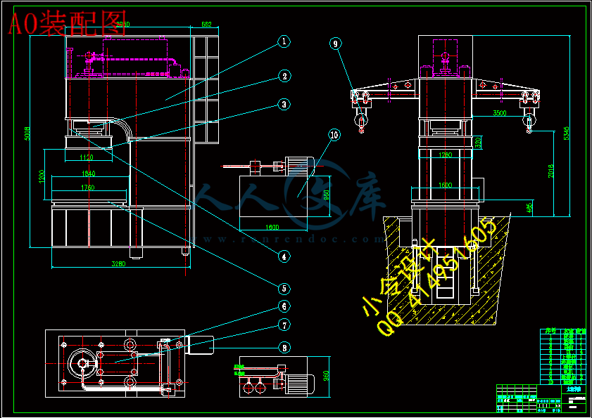
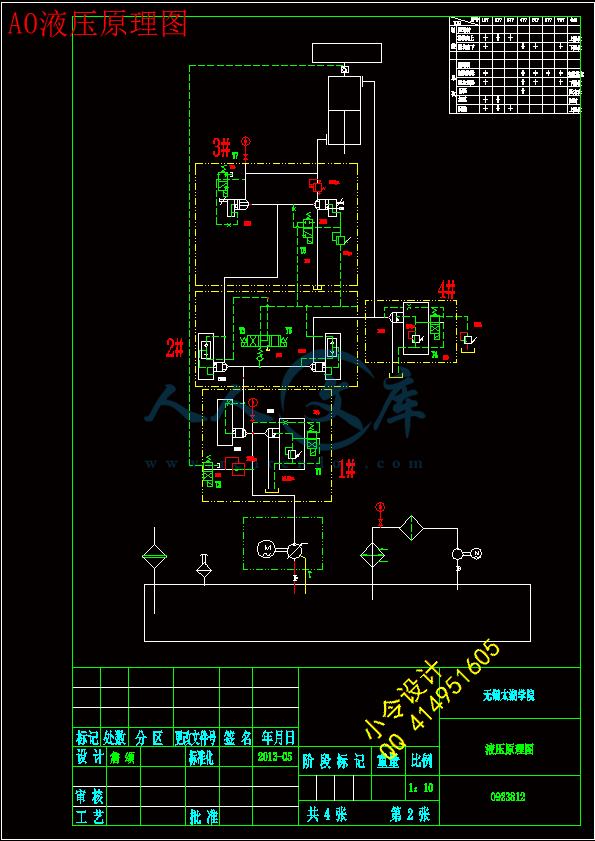
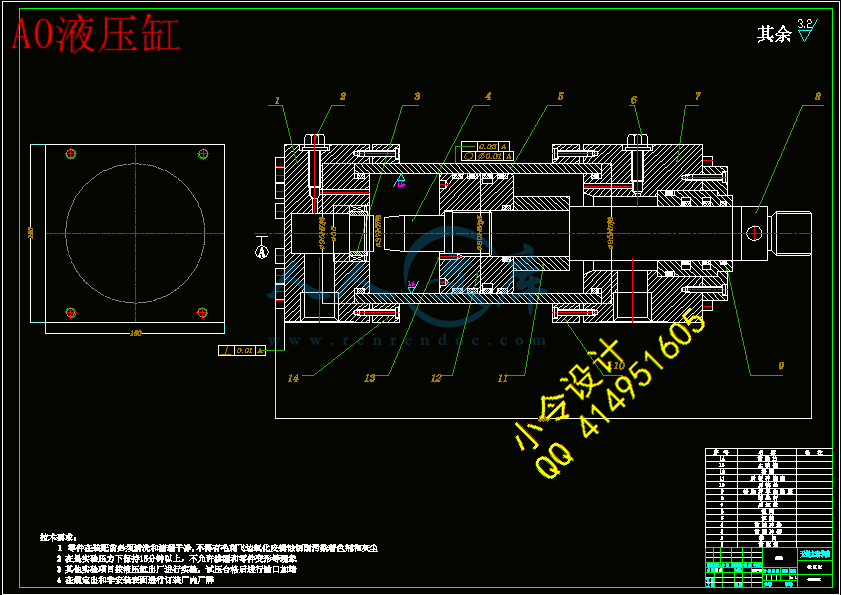
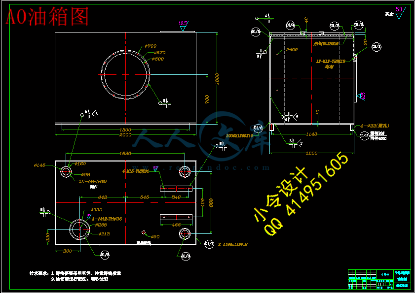
5000KN单臂液压机的液压系统设计【4张CAD图纸+毕业论文】

收藏

压缩包内文档预览:
预览图 预览图 预览图 预览图 预览图 预览图 预览图 预览图 预览图 预览图 预览图 预览图
编号:435832    类型:共享资源    大小:1002.31KB    格式:RAR    上传时间:2015-05-26 上传人:好资料QQ****51605 IP属地:江苏
45
积分
关 键 词:
kn 液压机 液压 系统 设计
资源描述:

【温馨提示】 购买原稿文件请充值后自助下载。

[全部文件] 那张截图中的文件为本资料所有内容,下载后即可获得。


预览截图请勿抄袭,原稿文件完整清晰,无水印,可编辑。

有疑问可以咨询QQ:414951605或1304139763


摘 要

液压传动相对于机械传动来说是一门新技术,液压机是利用帕斯卡定律制成的利用液体压强传动的机械,广泛应用于各种工业中。而在液压机中液压传动系统是其非常重要的组成部分,对液压机的各种性能起到决定性的作用,至于它与微电子和计算机技术密切结合,得以在尽可能小的空间内传递出尽可能大的功率并加以精确控制,更是近几十年内出现的新事物。

本文为5000KN单臂液压机设计了液压传动系统,500T单臂校正压装液压机液压系统采用插装阀集成系统,动作可靠,使用寿命长,液压冲击小,减小了连接管路与泄漏点。独立的电器控制系统,工作可靠,动作直观,维修方便。采用按钮集中控制,设调准(点动),单次(半自动)二种操作方式。大大的提高了传统液压机的控制有欠缺自动化、操纵性和安全性差等缺点。

它适用于轴类零件、型材的校正和轴套类零件的压装、板材零件的弯曲、压印、套形、简单零件的拉伸塑料制品、机床、内燃机、轻纺制造机械、轴类、轴承、洗衣机、汽车电机、空调电机、电器、军工企业、三资企业装配流水线等行业使用。

该设计主要包括在给定参数情况下液压系统零部件的参数计算,从而进行合适的选择,在根据实际情况确定液压元件(辅助元件)以及液压泵站和油箱,文章也附带了液压元件的安装说明及液压机的技术要求和液压机的驱动要求。


   关键词:单臂液压机;液压系统 ;液压元件


Abstract

Hydraulic transmission is a new technology compared with the mechanical transmission.  The hydraulic press is based on the Pascal’s law and designed for producing heavy press. The hydraulic drive system is an important part in the hydraulic press system. And it is the fateful element for the techniques of hydraulic press system. When closely combing with microelectronics and computer technology, it is able to deliver as far as possible big power and precise control within as little space as possible, especially in recent years it is a new thing.

   This paper is designed for 5000 KN single arm hydraulic press hydraulic transmission system, 500t single arm correction hydraulic press hydraulic system adopts cartridge valve integrated system installation with the advantages to reliable, long service life, small hydraulic impact, reducing the connection pipe and the leak point. The Independent electric control system, has the advantages of the work reliable, intuitive, easy maintenance. With the using of centralized control buttons, alignment (or points) and single (semi-automatic) ,two kinds of operating mode, greatly improve the traditional hydraulic control with lack of automation, poor maneuverability and security flaws.

   It is suitable for shaft parts, profile correction and sleeve parts, bending, stamping of sheet parts installation, set of form, the simple components of the tensile plastic products, machine tools, internal combustion engines, textile manufacturing machinery, shaft, bearing, washing machine, automobile motor, air conditioner motor, electrical appliance assembly line, military industrial enterprises, joint ventures, etc.

   This design mainly includes the system preliminary design is in such a case that the estimated parameters is determined and the loop forms of some circumstances, hydraulic components and connecting lines are fully determined. The design of the system has the performance analysis and performance checking to deal with the actual situation. I determine hydraulic components (secondary element), and hydraulic pump stations and tank. The article also comes with the installation instructions of hydraulic components and technical requirements of hydraulic press and hydraulic press driven by demand.


Key words: Single arm hydraulic press;Hydraulic system; Hydraulic components


目  录

AbstractIV

目  录V

1绪论1

1.1 液压机的介绍1

1.1.1液压机的工作原理1

1.1.2液压机的分类1

1.2液压形成的技术优点2

1.3液压传动系统的简介及发展趋势2

1.3.1 液压传动的概念及其优缺点2

1.3.2 液压系统的组成3

1.3.3液压系统的维护3

1.4本课题的研究内容和意义4

1.5国内外的发展概况4

1.6本课题应达到的要求5

2 5000KN液压系统参数及略见图6

2.1 表2-1各型号单臂液压机参数(500T)6

2.2 5000kN单臂液压机(略见图纸)7

3 单臂液压机液压系统设计8

3.1 液压系统零部件的参数计算与选择8

3.1.1 电机的选用8

3.1.2 液压缸的载荷组成与计算8

3.2液压元件的选用13

3.2.1液压阀的选定14

3.2.2单向阀的选择15

3.2.3溢流阀的选择16

3.2.4电液换向阀的选择16

3.2.5 电磁换向阀的选择17

3.2.6顺序阀的选定17

3.3过滤器的选定18

3.3.1回油过滤器的选择18

3.3.2空气过滤器的选择19

3.4压力表及压力表辅件的选择19

3.4.1压力表的选定19

3.4.2压力表开关的选定20

3.5液位仪表的选定20

3.6管件的选定21

3.6.1管路尺寸参数的确定21

3.6.2管接头的确定21

3.7油箱的设计确定22

3.7.1初选油箱容积22

3.7.2油箱的结构设计22

3.8 液压泵站的选用24

4 液压元件的安装说明和驱动要求26

4.1 液压元件的安装说明26

4.2 液压机的安全使用及液压驱动要求26

4.2.1安全防护26

4.2.2装配质量26

4.3 液压驱动要求27

5 结论与展望28

5.1 结论28

5.2不足之处与展望28

致 谢30

参考文献31


  1绪论

1.1 液压机的介绍

 1.1.1液压机的工作原理

    液压机是利用帕斯卡定律制成的利用液体压强传动的机械。按传递压强的液体种类来分,有油压机和水压机两大类。油压机是一种专用液压油和乳化油做为工作介质,用液压泵作为动力源件,靠液压泵的压力使液压油通过液压管道进入活塞和油缸,然后油缸和活塞有几组互相配合的密封件,不同位置的密封件是不同的,但都起到密封的作用,使液压油不能泄露。最后通过各种阀改变液压油方向并在油箱循环使油缸和活塞循环做功从而完成一定机械动作的机械。[1]

 1.1.2液压机的分类

按用途主要分为金属成型、折弯、拉伸、冲裁、粉末(金属,非金属)成型、压装、挤压等。

按结构形式主要分为:四柱式、单柱式(C型)、卧式、立式框架等。

与传统的冲压工艺相比,液压成形工艺在减轻重量、减少零件数量和模具数量、提高刚度与强度、降低生产成本等方面具有明显的技术和经济优势,在工业领域尤其是汽车工业中得到了越来越多的应用。

在控制方面主要有电控,机控与手控三大类。电控液压设备通过电磁铁操纵有关的换向阀,实现其控制的目的,这是主要的液压设备。对于它多采用标准液压元件,所以拆卸比较方便,设备储存液方便的,这对于故障分析是很有利的。

   机控液压机的设备信息取决于机构的运动。例如在车床与刨床的液压系统就是通过行程限位控制运动方向,对于它工作压力及传动功率偏低,运行环境适中,磨损速度相对是比较慢。

手控液压机设备的信息是取决于操作者,手控液压设备运行环境比较差,元件磨损速度快。

1.2液压形成的技术优点

在汽车工业及航天、航空等领域,缩短工艺时间节约资源是人们长期追求的目标,也是先进制造技术发展的趋势之一。液压成形(hydroforming)就是为实现速度快和量化的一种先进制造技术。与传统的冲压工艺相比,液压成形工艺在重量、数量和成本有很大的优势,它不仅提高工件的刚度与强度、大大降低生产中成本等方面所具有明显的经济优势,在工业领域尤其是汽车工业中(主要是汽车的外壳的冲压)得到了越来越多的实用价值。液压成形技术广泛的应用汽车、航空、航天和管道等行业,主要适用于:沿构件轴线变化的圆形、矩形或异型截面空心结构件,如汽车的排气系统异型管件;非圆截面空心框架,如发动机托架、仪表盘支架、车身框架;空心轴类件和复杂管件等。

液压成形工艺的适用材料包括碳钢、不锈钢、铝合金、铜合金及镍合金等,原则上适用于冷成形的材料均适用于液压成形工艺。与冲压工艺相比,液压成形技术和工艺有以下主要优点[2]:

1.减轻质量,节约材料。对于汽车发动机托架、散热器支架等典型零件,液压成形件比冲压件减轻15%~45%;对于空心阶梯轴类零件,可以减轻30%~45%的重量。

2.减少零件和模具数量,降低模具费用。液压成形件通常需要1套模具,而冲压件大多需要多套模具。液压成形的发动机托架零件由6个减少到1个,散热器支架零件由17个减少到7个,大大减少了资源。

3.可减少后续机械加工和组装的焊接量。

4.降低生产成本。根据对已应用液压成形零件的统计分析,液压成形件的生产成本比冲压件平均降低16%~21%,模具费用降低28%~38%。

 5.提高强度与刚度,尤其是疲劳强度,如液压成形的散热器支架,其刚度在垂直方向可提高40%,水平方向可提高47%。

   液压机技术特点:

(1)本系列液压机适合于可塑性材料的压制工艺,如冲压、弯曲、拉伸等。

(2)也可以从事校正、压装、塑料制品及粉末制品的压制成型。


内容简介:
Hydraulic System There are only following three basic methods of transmitting power : electrical,mechanical ,and fluid power. Most applications actually use a combination of the three methods to obtain the most efficient overall system. To properly determine which principle method to use, it is important to understand the characteristic of each method. For example,hydraulic systems on the long distance economically deliver power more than mechanical systems. However, fluid systems are restricted to shorter distances than electrical systems. Hydraulic power transmission systems are concerned with the generation, modulation, and control of sculptress and flow, and in general such systems include: l. Pumps convert available power from the prime mover to hydraulic power at the actuator. 2. Valves control the direction of pump- flow, the level of produced power, and the amount of fluid-flow to the actuators. The power level is determined by controlling both the flow and pressure level. 3. Actuators convert hydraulic power to usable mechanical power output at the point required. 4. The medium is a liquid, provides rigid transmission and control as well as lubrication of components, sealing in valves, and cooling of the system. 5.Connectors link the various system components, provide power conductors for the fluid under pressure, and fluid flow return to tank(reservoir). 6. Fluid storage and conditioning equipment ensure sufficient quality and quantity as well as cooling of the fluid. Hydraulic systems are used in industrial applications such as stamping presses, steel mills and general manufacturing, agricultural machines, mining industry, aviation, space technology, deep-sea exploration, transportation, Narine technology, and offshore gas and petroleum exploration. In short, many people get somehow benefiting from the technology of hydraulics. The secret of the success and widespread use of the hydraulic system is its versatility and manageability. Fluid power is not hindered by the geometry of the machine as is the case in mechanical systems. Also, power can be transmitted in almost limitless quantities because fluid systems are not so limited by the physical limitations of materials as are the electrical systems. For example, the performance of an electromagnet is limited by the saturation limit of steel. On the other hand, the power limit of fluid systems is limited only by the strength capacity of the material. Industry is going to depend more and more on automation in order to increase productivity. This includes remotion and direct control of production operations, manufacturing processes, and materials handling. Fluid power is the muscle of automation because of the advantages in the following four major categories. 1. Ease and accuracy of control. By the use of simple levers and push buttons, the operator of a fluid power system can readily start , stop ,speed up or slow down, and provide any desired horsepower with tolerances as precise as one ten-thousandth of an inch. 2. Multiplication of force. A fluid power system (without using cumbersome gears, pulleys, and levers) can multiply force simply and efficiently create the output from a fraction of an ounce to several hundred tons. 3. Constant force or torque. Only fluid power systems are capable of providing constant force or torque regardless of speed changes. It produces the work output moving from a few inches per hour to several hundred inches per minute, or from a few revolutions per hour to thousands of revolutions per minute. 4. Simplicity, safety, economy. In general, fluid power systems use fewer moving parts than comparable mechanical or electrical systems. Thus, they are simpler to maintain and operate. This, in turn, maximizes safety, compactness, and reliability. For example, a new power steering control design has made all other kinds of power systems obsolete on many off-highway vehicles. The steering unit consists of a manually operated directional control valve and meter in a single body. Because the steering unit is fully fluid-linked, without the link of mechanical linkages, universal joints, bearings, reduction gears, etc. This provides a simple, compact system. In addition, very little input torque is required to produce the control needed for the toughest applications. This is important where limitations of control space require a small steering wheel and it becomes necessary to reduce operator fatigue. Additional benefits of fluid power systems include instantly reversible motion, automatic protection against overloads, and infinitely variable speed control. Fluid power systems also have the highest horsepower per weight ratio of any known power source. In spite of all these highly desirable features of fluid power, it is not a panacea for all power transmission problems. Hydraulic systems also have some drawbacks. Hydraulic oils are messy, and leakage is impossible to completely eliminate. Also, most hydraulic oils can cause tires if an oil leak occurs in an area of hot equipment.Now, a concrete example is following - we use hydraulic stations to introduce the advantages of the hydraulic system. Hydraulic Station and the development of hydraulic components Profiles Hydraulic Pump Station also known as the stations is independent hydraulic device. It is requested by the oil gradually and controls the hydraulic oil flow direction, pressure and flow rate, applied to the mainframe and hydraulic devices ability of hydraulic machinery. Users just need to connect hydraulic station and host of implementing agencies (motor oil or fuel tanks) with tubing. Hydraulic machinery can realize these specified movements and the work cycle. Hydraulic pump station is equipped with Pump device, manifold or valve portfolio, tanks, electrical boxes. Pump device - is equipped with motors and pumps. Hydraulic station is the source of power and can translate mechanical energy into hydraulic oil pressure. Manifold - is installed by hydraulic valve and assembled channel. It has the function of adjusting the direction for implementation of hydraulic oil, pressure and flow. Valve portfolio - plate valve is installed in up board, the back board connects and has the same functional with IC. Tank - plate welding semi-closed containers, also is loaded with oil filtering network, air filters ans is used to save oil, oil filters and cooling. Electrical boxes - has the two patterns. A set of external fuse terminal plate and a full range of control electrical. The principle of the hydraulic Station: the motor drives pump rotation, pump absorbs oil from the oil tank, then translates mechanical energy into hydraulic pressure of the station. Hydraulic oil through Manifold (or valve combinations) realized the direction, pressure. After adjusting flow pipe, it external flows to the cylinder hydraulic machinery or motor oil, so as to control the direction of the motive fluid, the size of transformation force and the speed of the pace, finally it promotes hydraulic machinery to the various acting. Firstly, A development course China Hydraulic (including hydraulic, the same below), pneumatic and seals industrial development process can be broadly divided into three phases, namely : the early 1950s to the early 1960s is the initial stage. The 60s and 70s is the growth stage for specialized production system.The80s-90s is the growth stage for the rapid development .Meanwhile, hydraulic industry started in the early 1950s from the machine tool industry production of fake us-grinder, broaching machine, copying lathe, and other hydraulic drive. Hydraulic Components from the plant hydraulic machine shop is self-occupied. After entering the l960s, the application of hydraulic technology from the machine gradually extended to the agricultural machinery and mechanical engineering fields, attached to the original velocity of hydraulic shop some stand out as pieces of hydraulic professional production. To the late 1960s, early 1970s, with the development of mechanized production, especially the second automobile factory provides efficient, automated equipment. The Hydraulic Components manufacturing has experienced rapidly development of the situation. Groups of SME have become professional hydraulic parts factory. China annual output of hydraulic components has nearly 200.000 in 1968. Machine tools, agricultural machinery, mechanical engineering industries, the production of hydraulic parts factory have been the professional development of more than 100 and an annual output more than one million in 1973 and an independent hydraulic manufacturing industry has begun to take shape. Then , hydraulic pieces of fake products has developed from the Soviet Union for the introduction of the product and combining the products .Hypertension has developed to medium and high pressure and the development of the electro-hydraulic servo valves and systems, hydraulic application areas further expanded .Pneumatic industry started later than the industrial hydraulic years. Until 1967 professional pneumatic components factory began to establish . Pneumatic Components looked only as commodity production and sales. It deal with rubber and plastics, mechanical seals and sealing flexible graphite . In the early 1950s, it produced ordinary 0-rings, rubber and plastics extrusion, such as oil seal sealing and seal asbestos. Until the early 1960s,it begun to production of mechanical seals and flexible graphite sealing products. In 1970s, under the burning of the former Ministry, a Ministry, the Ministry of Agricultural Mechanization System, a group of professional production plants have been established, and the official establishment of industries to seal industrial development has laid the foundation for growth. Since the l980s, under the guidelines of countrys reform and opening up policy , with the development of the machinery industry, based mainframe pieces behind the conflicts have become increasingly prominent and attracted the attention of the relevant departments. To this end, the Ministry originating in 1982 and formed the basis of common pieces of Industry, will centralize hydraulic, pneumatic and seals specialized factories original machine tools scattered in agricultural machinery, mechanical engineering industries and place them under common management infrastructure pieces Bureau, so that the industry in the planning, investment, technology and scientific research and development in areas got the guidance and support of infrastructure pieces Bureau. Since then it entered a phase of rapid development and has introduced more than 60 items of advanced technology from abroad, including more than 40 items of hydraulic, pneumatic 7. After digestion and absorption and transformation, now they have mass production, and industry-leading products. In recent years, the industry has increased the technological transformation efforts.Fom1991 to 1998,state,Local enterprises and the self-Financing have fund total input of about 20 billion ¥, of which Hydraulic was more than I .6 billion¥ . Through technological transformation and technology research, a number of major enterprises have further improved the level of technology, technique and equipment, which has laid a good foundation in order to form a higher Starting point, specialization, and run production . In recent years, under the guidelines of development of common ownership, different ownership SME rapidly have rise to show great vitality. With the further opening up, three-funded enterprises developed rapidly which played an important role to the development of industry standards and expanding exports. Today, China and the United States, Japan, Germany and other countries famous manufacturers have established joint ventures or wholly-owned by foreign manufacturers which involved in a piston pump / motor, planetary reduction gears, steering gear, hydraulic control valve, hydraulic system, hydrostatic transmission, hydraulic Casting, pneumatic control valve, cylinder, gas processing triple pieces, mechanical seals, rubber and seal products. It has more than 50 production enterprises and attracted foreign investment over 200 million U.S. dollars. Secondly, the current situation (1)Basic Profiles After 40 years of efforts, China hydraulic, pneumatic and sealing industry have formed the industrial system with a relatively complete categories, a certain level of technical capacity. According to the 1995, Third National Industrial Census statistics said that state-owned, village-run, private and cooperative enterprises, individual, “three capital” enterprises with a total of more than 1,300 engaged in hydraulic Pneumatic and sealing parts industry with annual sales income of 100 million¥, of which hydraulic is about 700, Pneumatic and sealing parts industry is approximately300. By 1996 with the international trade statistics, the total output value of Chinas hydraulic industry is 2.348 billion¥, accounting for the worlds 6, the output of Pneumatic industry is 419 million¥, accounting for world No. 10. (2)The current supply and demand profiles Through the introduction of technology, independent development and technological innovation, high-pressure piston pump, gear pumps, vane pump, General Motors hydraulic valves, tanks, non-lubricated aerodynamic pieces and various seals of the first large technology products have increased noticeably and they can have stability mass production and provide a level of assurance for various mainframe products. In addition, they scored some achievements at hydraulic and pneumatic components of the CAD system, pollution control, proportional servo technology, and have been already in production. Currently, hydraulic, pneumatic and seals products totally have about 3,000 species, more than 23.000 specifications. Among them, there are 1,200 hydraulic varieties, more than I 0,000 specifications (including hydraulic products 60 varieties,500 specifications): Pneumatic has 1 .350 varieties, more than 8,000 specifications: Rubber seal has 350 species, more than 5,000 specifications, they basically cater to the different types of mainframe products to the general needs. The complete sets of equipment for major varieties of matching rate was over 60%, and it started a small amount of exports. In 1998 the output of homemade hydraulic is 4.8 million, the sales of which is about 28 billion (of which about 70% is mechanical systems);The yield of aerodynamic is 3.6 million, Sales of which is about 5.5 billion (of which about 60% is mechanical systems). Seals output is about 800 million, sales of which is about 10 billion (of which about 50% is mechanical systems). According to the China 1998 annual Hydraulic Pneumatic Seals Industry Association, the rate of hydraulic product sales is 97. 5% (101% for hydraulic), pneumatic 95.9%, sealed 98.7%. This fully reflects the basic marketing convergence. Our country hydraulic, pneumatic and sealing industry have attained a great deal of progress, but compared with mainframe development needs, and the worlds advanced level, there are still many gaps, mainly reflected in the product variety, performance and reliability, and so on. Hydraulic products as an example, is the same one-third of products abroad. life is for half abroad. In order to meet key mainframe, and mainframe imports of major technology and equipment needs, every year we import a large number of hydraulic, pneumatic and sealing Products. According to customs statistics and the analysis of data, in 1998,the import sales of hydraulic, pneumatic and seals is about 200 million U.S. dollars, which Hydraulic is about 1.4 billion dollars, aerodynamic is nearly 0.3million U.S. dollars, sealed industry is about 0.3million U.S. dollars. It is a slight decline compared with 1997 . By sums, currently the domestic market share of the imported products is about 30%. In 1998 ,the demand of domestic hydraulic market is total of about six million, the total sales is nearly 40 billion. The total demand of aerodynamic is about 5 million, with sales more than 0.7 billion ¥The total demand of Seals is about 1.1 billion, the total sales is about 1.3 billion. Thirdly, the development trend of the future 1.the main factors of affecting the development (1) The product development ability, and the level of technological development and speed can not completely meet the advanced mainframe products, major equipment and technology imported equipment and maintenance support: (2) The manufacturing technology, the level of equipment and management standards of A number of enterprises are comparatively backward, along with a week sense of quality, which result in low levels of product performance quality, reliability poor services in a timely manner, lack of satisfaction and trust of the brand-name products: (3) The production low of industry specialization, scattered strength, low repeat serious, the convergence products between regions and enterprises, blindly competing with each other, driving down prices, the decline of enterprise returns, lack of funds, difficult liquidity, the inadequate product development and technological transformation seriously have restricted the industry to improve the overall level of competition and competitive strength. (4) As the internationalization of the domestic market is increasing, foreign companies have entered the Chinese market and participate in competition with the domestic private and cooperative enterprises, individuals, foreign-funded enterprises and so on. As the rise of state-owned enterprises has more and more big impact to state-owned enterprises. 2 .The development trend As the socialist market economy continues to deepen, the relationship of supply and demand of hydraulic, pneumatic and sealing products in the market has a greater change. Long ago, the characterized by shortage of the sellers market has basically become the characterized by excess structural buyers market. Look from the overall ability, it is in oversupply situation, especially the supply of the generally low grade of hydraulic, pneumatic and sealing parts, generally exceeds the demand, but the host need high parameters of high technical content, high value-added high-end products, and cant meet the needs of the market, it can only rely on imports. After Chinas accession to the WTO, its impact could be bigger. Therefore, during 15 , the growth of the industry output value must not be dependent on the amount of growth and should increase, adjust the industrial structure and product structure according to the structural contradiction of industry , namely we should rely on quality, technology upgrade, promote products to meet the market demand and pull, seek a bigger development. Pneumatic pressure systemPneumatic pressure system is pressure gas transmission system and control power, as the name suggests, usually it uses air pressure (no other gas) as the fluid medium. Because air is a safe, low cost and widely available fluid. It is safe that Air in system components may ignite the leakage situation (using air as medium) in particular. In pneumatic systems, compressors are used for compressed air and supply the required. Usually it has a piston compressor, screw and vane type. Compressor is basically according to the ideal gas law, by reducing its volume to increase the gas pressure. Pneumatic system is usually considered using large central air compressor as an unlimited source, this is similar that as long as the plug in the power system lift up into the socket and power can be obtained. Using this method, the gas pressure can be transmitted from the source to every corner of the whole factory. The gas pressure can remove dirt through the air cleaner. the dirt is likely to damage the gas components of precision parts such as valve and cylinder, etc, and then is transported to each loop, and then the air flowing through the pressure reducing valve to reduce the pressure value is suitable for a primary circuit. Because air is not a good lubricant (including 20% oxygen), air pressure system needs a oil mist detector , then uses it to inject oil mist to air for reducing valve and pressure relief in the air, this will help reduce precision pneumatic components with moving parts wear and tear. Air from the atmosphere contains different amounts of water. The water can be harmful, it can take lubricants to cause excessive wear and corrosion. Therefore, in some occasions, we use air dryer to remove these harmful moisture because the air pressure system directly discharges into the atmosphere, it can produce too much noise, so components can be performed in the valve and vent installed muffler to reduce noise, to prevent the operator due to exposure to noise and high speed air particles may cause damage. Using pneumatic system has the following several reasons instead of the hydraulic system: liquid inertia is far larger than gas. Therefore, in fluid system, the acceleration deceleration and valve open shut down suddenly when we execute components, the quality of the oil is a potential problem. According to the Newtons laws of motion (force equals mass times acceleration), the force accelerating motion acceleration required to the number of produce oil that are equally many times the volume needed for the air force. Gas liquid ratio has a larger viscosity, it causes more pressure and power loss because of the cold brush. In addition, due to the using of the liquid will cut off from the atmosphere in hydraulic system , so they need special mailbox and leak proof system design. Pneumatic systems can be used directly into the surrounding environment in the air. In general no liquid pressure system is more expensive. However, due to the compressibility of air, the air system execution components may not get a precise speed control and position control. Due to limited compressor of air pressure system, the system pressure is low (less than 250 ops), but fluid pressure is of up to 10000 pa. So it can be a large power system. Air pressure system is used only for small power system. A typical example, it apples for punching, drilling, promoting, punching and clamping, the assembly and riveting, material processing and logic control operation, etc.液压与气动系统 仅有以下三种基本方法传递动力:电气、机械和流体。大多数应用系统实际上是将三种方法组合起来而得到最有效地最全面的系统。为了合理地确定采取哪种方法,重要的是了解各种方法的显著特征。例如液压系统在长距离上比机械系统更能经济地传递动力。然而液压系统与电气系统相比,传递动力的距离较短。液压动力传递系统涉及电动机、调节装置和压力,流量控制。总的来说,该系统包括:l 泵:将原动机的能力转换成作用在执行部件上的液压能。 2 阀:控制泵产生流体的运动方向、产生的功率的大小,以及到达执行部件液体的流量。功率大小取决于对流量和压力大小的控制。 3 执行部件:将液压能转换成可用的机械能。 4 介质即油液:可进行无压缩传递和控制,同时可以润滑部件,使阀体密封和系统冷却。5联接件:联接各个系统部件,为压力流体提供功率传输通路,将液体返回邮箱。 6 油液贮存和调节装置:用来确保提供足够质景和数量并冷却的液体。液压系统在工业中应用广泛,例如冲压,钢类工件的磨削及一般加工业、农业、矿业、航大技术、深海勘探、运输、海洋技术,近海天然气和石油勘探等行业,简而言之,在日常生活中很少有人不从液压技术中得到某种益处。液压系统成功而又广泛使用的秘密在与它的通用性和易操作性。液压动力传递不会像机械系统那样受到机器几何形体的制约,另外,液压系统不会像电气系统那样受到钢的磁饱和极限的限制。相反,液压系统的功率仅仅受材料强度的限制。企业为了提高生产率将越来越依靠自动化,这包括远程和直接控制生产操作、加工过程和材料处理等。液压动力之所以成为自动化的重要组成部分,是因为它有如下主要的四种优点: 1 控制方便精确通过操作一个简单的操作杆和按钮,液压系统的操作者便能立即起动、停止、加减速和能提供任意功率、位置精度为万分之一英寸的位置控制力。 2 增力 一个液压系统(没有使用笨重的齿轮、滑轮和杠杆)能简单有效地将不到一盎司的力放大产生几百吨力的输出。 3 恒力或恒扭 只有液压系统能提供不随速度变化而变化的恒力或恒扭矩,它可以驱动对象从每小时移动几英寸到每分钟几百英寸,从每小时几转到每分钟几千转。 4 简便、安全、经济 总的来说,液压系统比机械或电气系统使用更少的运动部件,因此,它们运行与维护简便。这使得系统结构紧凑,安全可靠。例如一种用于车辆上的新型动力转向控制装置己淘汰其他类型的转向动力装置,该转向部件中包含有人力操纵方向控制阀和分配器。因为转向部件是全液压的,没有万向节、轴承、减速器齿轮等机械连接,这使得系统简单紧。另外,只需输入很小的扭知就能产生满足极恶劣工作条件所需的控制力,这对于因操作空间限制而需要小方向盘的场合很重要,这也是减轻司机疲劳度所必需的。 液压系统的其他优点包括双向运动、过载保护和无极变速控制,在己有的任何动力系统中液压系统亦具有最大的单位质量功率比. 尽管液压系统具有如此高性能,但它不是可以解决所有动力传递问题的灵丹妙药。液压系统也有些缺点,液压油油污染,并且泄漏不可能完全避免,另外如果油液渗漏发生在灼热设备附近,大多数液压油能引起火灾。下面以一具体实例 -液压站来介绍液压系统的优越性。 液压站又称液压泵站,是独立的液压装置。它按逐级要求供油。并控制液压油流的方向、压力和流量,适用于主机与液压装置可分离的各种液压机械上。用户购后只要将液凡站与主机上的执行机构(油缸或油马达)用油管相连,液压机械即可实现各种规定的动作和工作循环. 液压站是由泵装置、集成块或阀组合、由箱、电气盒组合而成。各部件功能:泵装置-上装有电机和油泵,是液压站的动力源,将机械能转化为液压油的压力能。集成块-由液压阀及通道体组装而成。对液压油实行方向、压力和流量调节。 阀组合-板式阀装在立板上,板后管连接,与集成块功能相同。油箱-板焊的半封闭容器,上还装有滤油网、空气滤清器等,用来储油、油的冷却及过滤。 电气盒-分两种型式。一种设置外接引线的端子板:一种配置了全套控制电器。液压站的工作原理:电机带动油泵转动,泵从油箱中吸油供油,将机械能转化为液压站的压力能,液压油通过集成块(或阀组合)实现了方向、压力、流最调节后经外接管路并至液压机械的油缸或油马达中,从而控制液动机方向的变换、力量的大小及速度的快慢,推动各种液压机械做功。一 发展历程 我国液压(含液力,下同)、气动和密封件工业发展历程,大致可分为三个阶段,即:20世纪50年代初到60年代初为起步阶段:60-70 年代为专业化生产体系成长阶段;80-90年代为快速发展阶段。其中,液压工业于50年代初从机床行业生产仿苏的磨床、拉床、仿形车床等液压传动起步,液压元件由机床厂的液压车间生产,自产自用进入60年代后,液压技术的应用从机床逐渐推广到农业机械和工程机械等领域,原来附属于主机厂的液压车间有的独立出来,成为液压件专业生产厂。到了60年代末、70年代初,随着生产机械化的发展,特别是在为第二汽车制造厂等提供高效、自动化设备的带动下,液工压元件制造业出现了迅速发展的局面,一批中小企业也成为液压件专业制造厂。1968年中国液压元件年产景已接近20万件:1973年在机床、农机、工程机械等行业,生产液抓件的专业厂己发展到100余家,年产量超过100万件,一个独立的液压制造业己初步形成。这时,液压件产品已从仿苏产品发展为引进技术与自行设计相结合的产品,压力向 中、高压发展,并开发了电液伺服阀及系统,液压应用领域进一步扩大。气动工业的起步比液压稍晚儿年,到1967 年开始建立气动元件专业厂,气动元件才作为商品生产和销售。含橡塑密封、机械密封和柔性石墨密封的密封件工业,50 年代初从生产普通0 型圈、油封等挤压橡塑密封和石棉密封制品起步,到60 年代初,开始研制生产机械密封和柔性石墨密封等制品。70年代,在原燃化部、一机部、农机部所属系统内,一批专业生产厂相继成立,并正式形成行业,为密封件工业的发展成长奠定了墓础。 进入80年代,在国家改革开放的方针指引下,随着机械工业的发展,基础件滞后于主机的矛盾日益突出,并引起各有关部门的重视。为此,原一机部于1982年组建一通用基础件工业局,将原有分散在机床、农业机械、工程机械等行业归口的液压、气动和密封件专业厂,统一划归通用基础件局管理,从而使该行业在规划、投资、引进技术和科研开发等方面得到基础件局的指导和支持。从此进入了快速发展期,先后引进了60余项国外先进技术,其中液压40余项、气动7项,经消化吸收和技术改造,现均己批量生产,并成为行业的主导产品。近年来,行业加大了技术改造力度,1991 -1998年国家、地方和企业自筹资金总投入共约20多亿元,其中液压16亿多元。经过技术改造和技术攻关,一批主要企业技术水平进一步提高,工艺装备得到很大改善,为形成高起点、专业化、批量生产打下了良好墓础。近几年,在国家多种所有制共同发展的方针指引下,不同所有制的中小企业迅猛崛起,呈现出勃勃生机。随着国家进一步开放,三资企业迅速发展,对提高行业水平和扩大出口起着重要作用。目前我国己和美国、日本、德国等国家著名厂
温馨提示:
1: 本站所有资源如无特殊说明,都需要本地电脑安装OFFICE2007和PDF阅读器。图纸软件为CAD,CAXA,PROE,UG,SolidWorks等.压缩文件请下载最新的WinRAR软件解压。
2: 本站的文档不包含任何第三方提供的附件图纸等,如果需要附件,请联系上传者。文件的所有权益归上传用户所有。
3.本站RAR压缩包中若带图纸,网页内容里面会有图纸预览,若没有图纸预览就没有图纸。
4. 未经权益所有人同意不得将文件中的内容挪作商业或盈利用途。
5. 人人文库网仅提供信息存储空间,仅对用户上传内容的表现方式做保护处理,对用户上传分享的文档内容本身不做任何修改或编辑,并不能对任何下载内容负责。
6. 下载文件中如有侵权或不适当内容,请与我们联系,我们立即纠正。
7. 本站不保证下载资源的准确性、安全性和完整性, 同时也不承担用户因使用这些下载资源对自己和他人造成任何形式的伤害或损失。
提示  人人文库网所有资源均是用户自行上传分享,仅供网友学习交流,未经上传用户书面授权,请勿作他用。
关于本文
本文标题:5000KN单臂液压机的液压系统设计【4张CAD图纸+毕业论文】
链接地址:https://www.renrendoc.com/p-435832.html

官方联系方式

2:不支持迅雷下载,请使用浏览器下载   
3:不支持QQ浏览器下载,请用其他浏览器   
4:下载后的文档和图纸-无水印   
5:文档经过压缩,下载后原文更清晰   
关于我们 - 网站声明 - 网站地图 - 资源地图 - 友情链接 - 网站客服 - 联系我们

网站客服QQ:2881952447     

copyright@ 2020-2025  renrendoc.com 人人文库版权所有   联系电话:400-852-1180

备案号:蜀ICP备2022000484号-2       经营许可证: 川B2-20220663       公网安备川公网安备: 51019002004831号

本站为文档C2C交易模式,即用户上传的文档直接被用户下载,本站只是中间服务平台,本站所有文档下载所得的收益归上传人(含作者)所有。人人文库网仅提供信息存储空间,仅对用户上传内容的表现方式做保护处理,对上载内容本身不做任何修改或编辑。若文档所含内容侵犯了您的版权或隐私,请立即通知人人文库网,我们立即给予删除!