周边传动刮泥机动力系统设计.doc

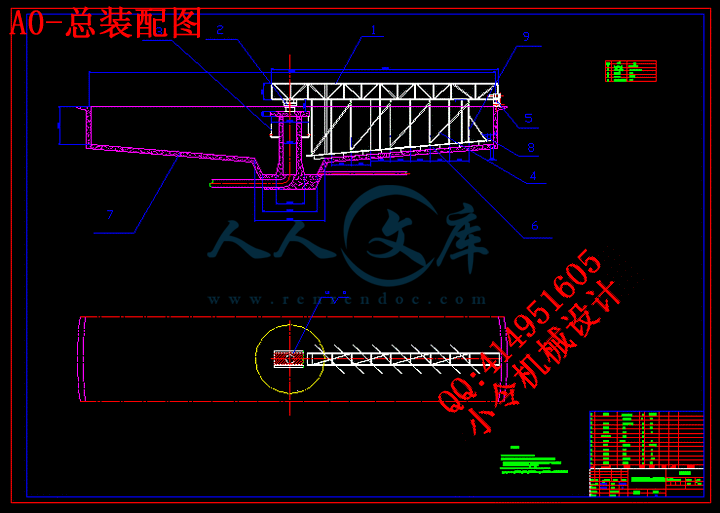
周边传动刮泥机动力系统设计【8张CAD图纸+毕业论文】【答辩优秀】

收藏

压缩包内文档预览:(预览前20页/共55页)
预览图 预览图 预览图 预览图 预览图 预览图 预览图 预览图 预览图 预览图 预览图 预览图 预览图 预览图 预览图 预览图 预览图 预览图 预览图 预览图
编号:436133    类型:共享资源    大小:763.69KB    格式:RAR    上传时间:2015-05-27 上传人:好资料QQ****51605 IP属地:江苏
45
积分
关 键 词:
周边 传动 机动力 系统 设计 全套 cad 图纸 毕业论文 答辩 优秀 优良
资源描述:

【温馨提示】 购买原稿文件请充值后自助下载。

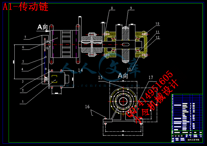
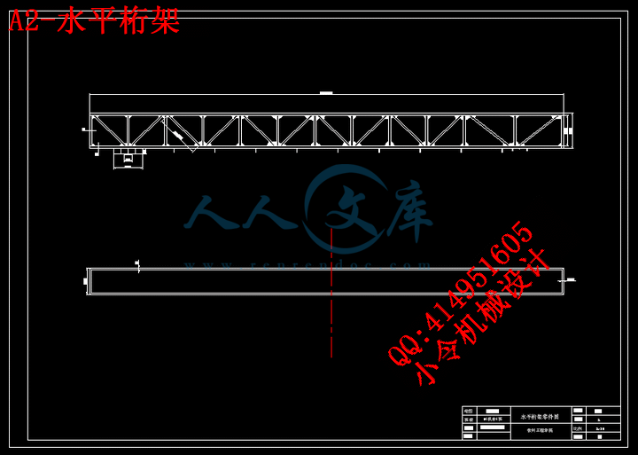
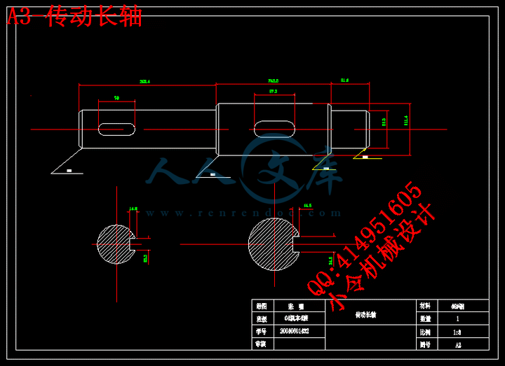
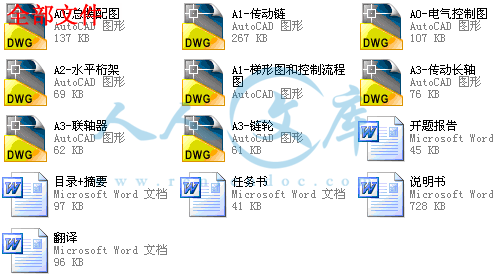
[全部文件] 那张截图中的文件为本资料所有内容,下载后即可获得。


预览截图请勿抄袭,原稿文件完整清晰,无水印,可编辑。

有疑问可以咨询QQ:414951605或1304139763

摘要

排泥机械是在自来水厂和污水处理厂中配合沉淀池使用的,它是重要的排泥专用设备。排泥机械的形式随工艺的条件与池形的结构而有所不同,目前常用的排泥机械可分为平流式(矩形)沉淀池排泥机和辐流式(圆形)排泥机两大类。刮泥机主要有周边传动式、中心传动式、矩形平流池桁车式、链传动式等。它是排泥机械中的一种常见设备,它是沉淀池不可缺少的设备。一般采用铝合金,不锈钢或防腐处理型钢制作,具有电动提肥,过载保护、撇渣、刮泥、虹吸排泥过程监控,电气联锁等特点,动力消耗低、防腐性能强、吸泥量可调、传动平稳、运行可靠。

本设计研究的刮泥机为周边传动式。并将可编程序控制器(PLC)应用于控制系统中,极大的简化操作过程,提高运行稳定性。具有结构简单,运转连续,管理方便等一系列优点。


关键词:可编程控制器;全自动运行;环保;刮泥机

Abstract

Arranges the putty machinery is in the Waterworks and the Sewage treatment plant,the coordinate sedimentation pond use,it is the important special purpose equipment. Arranges the putty machinery's form differs from along with the craft condition and the pond structure,at present the commonly used platoon putty machinery may divide into the advection type (rectangle) a sedimentation pond row of putty machine and the spoke class type (circular) the row of putty machine two broad headings. The mud scraper mainly has peripheral transmission type,central transmission type,the rectangular advection pond clothes rack car type,the chain drive type and so on. It is in the row of putty machinery's one kind of common equipment; it is the sedimentation pond essential equipment. Generally uses the aluminum alloy, the stainless steel or the antiseptic treatment section manufacture,has raises electrically operated fat, the over-load protection, casts aside the dregs,to blow the putty,the rainbow to attract the row of putty process monitoring,characteristics and so on electrical interconnection, the power consumption is low,the antiseptic property strong,attracts the putty quantity adjustable,the transmission to be steady,the movement is reliable.

This design research mud scraper for peripheral transmission type. And applies programmable controller (PLC) in the control system,the enormous simplification operating process,enhances the movement stability.Has the structure to be simple,the revolution is continual,manages the convenience and so on a series of merits.


Keywords:PLC  Completely automatic movement environmental  protection  Mud scraper


目       录

1 绪论1

1.1 我国的环保形势1

1.2 常用的的污水处理工艺简介2

1.2.1活性污泥工艺2

1.2.2氧化沟工艺2

1.2.3 A-O法及A-B法2

1.2.4 SBR法2

1.3 刮泥机简介及其在污水处理中的地位3

1.4 我国现存刮泥机的种类,各自的应用场合和优缺点3

1.5 本课题研发的刮泥机简介5

1.6 研究意义6

2 刮泥机总体设计7

2.1 本课题刮泥机的设计参数7

2.2 周边传动的总体构成7

2.2.1 全跨式7

2.2.2 半跨式7

2.2.3 中心旋转支座9

2.2.4 撇渣机构及刮板布置10

2.3 动力系统总体设计11

2.3.1 工作原理11

2.3.2 传动机构各部分的组成12

2.4 初沉池的设计12

2.4.1 高密度澄清池概况12

2.4.3高密度澄清池的三种类型13

2.4.4高密度澄清池的简介13

2.4.5初沉池设计参数13

3 动力系统设计与计算15

3.1 传动装置设计的要求15

3.2 电动机的选择15

3.2.1 选择合适的电动机16

3.2.2 电机驱动功率的计算与选择16

3.3 联轴器的设计18

3.3.1联轴器的分类18

3.3.2联轴器选择应考虑的问题19

3.3.3联轴器的选择19

3.4泵的选择20

3.4.1进水泵的选择20

3.4.2出水泵的选择21

3.5链轮的设计22

3.5.1链轮对齿形要求22

3.5.2链轮的主要设计参数22

3.5.3链轮的结构型式22

3.5.4链轮的材料要求22

3.6传动轴的设计与计算23

3.6.1 轴的概述23

3.6.2 轴的材料23

3.6.3 轴的强度计算23

3.6.4 轴的刚度计算24

3.6.5刮泥机传动轴的计算24

4 PLC控制系统的设计26

4.1 PLC控制系统的设计的主要内容26

4.2 PLC编写控制系统程序设计的步骤26

4.3 PLC的选择27

4.3.1 PLC容量的估算方法27

4.3.2 PLC存储容量的估算方法27

4.3.3 数字I/O点数与模块的确定27

4.3.4 输入模块的确定28

4.3.5 输出模块的确定28

4.3.6 PLC选型确定28

5电气控制系统的设计29

5.1电气控制系统的意义29

5.2绘制电气控制图的要求29

5.3刮泥机动力系统泥机总体方案29

5.4 主电路系统的设计30

5.4.1 控制系统的要求30

5.4.2 主电路的设计31

5.5 PLC外部接线设计31

5.6 交流控制线路设计33

5.7 主要参数设计34

结论35

致谢36

参考文献37

附录38

英文原文38

中文翻译44


1 绪论

1.1 我国的环保形势

作为发展中的社会主义国家,我国人民在现代化建设的过程中,面临比世界其他国家更为严峻人口、资源和环境形势。沉重的人口负担,人均资源不足,环境状况恶化,严重影响着党和政府发展经济的宏观决策,也影响着人民群众生活水平的提高,成为制约我国社会主义建设的首要问题。

改革开放三十多年来中国社会公众和各级领导干部的环保意识得到大幅提高,中国的社会环境、自然资源在很大程度上得到改善。但是,目前中国已经进入工业化中期和城市化迅速发展的时期,从发达国家的经历来看,这是消耗资源最多,对环境破坏最大的时期。为了社会的可持续发展,中国政府提出了全面、协调、可持续发展的科学发展观。改革开放,特别十一届四中全会以来,我国的环境保护工作有了长足的发展。

1.明确了环境保护为基本国策之一的地位,制定了中国自己的可持续发展战略。

1992年联合国环境与发展大会之后,我国率先提出了《环境与发展十大对策》,指定《中国21世纪议程》,《中国环境保护行动》等文件,实施可持续发展战略已成为国民经济和社会发展的基本指导方针。

2.建立了更为 的环境管理体制和法律机制

经过十多年的努力,在全国范围内初步建立起了环境保护部门监督管理,各有关部门分工负责的环境管理体系以及响应的环境监测、监理、统计、科研、宣传、教育体系。

到1997年,我国相继颁布了《环境保护法》等6部专门的环境法律,资源保护法律9部,环境行政法规28件,环抱部门发布环境规章70余件,环境标准390项。环保已经从主要依靠行政手段向着利用法律手段转移。

3.城市环境整治和工业污染防治取得了明显成效,环境保护已经从末端治理转变到源头控制。

4.环境外交和国际合作日益活跃

我国积极开展环境外交,参与各项重大的国际环境事务,在国际环境与发展领域中发挥月来越大的作用;签署并批准了《保护臭氧层维也纳公约》,《联合国气候变化框架会议》,《生物多样化公约》等多项国际环境公约。

每年,政府还投入了大量资金用于环境治理。其中与人民生活休戚相关的环保设备得到了极大的关注.在国内环保需求的拉动下,我国环保设备行业有了明显的进步。“十五”期间,全行业工业总产值同比增幅在15%以上,有的重点企业高达37%。其中,2006年水污染防治设备的产量与2005年相比增长6倍;固体废弃物处理设备的产量增加了31.18%;环境监测仪器的产量2006年也有了明显回升。但是,由于国产环保设备及仪器仪表档次不高,我国各行业的节能减排受到一定程度的制约。比如,国内开发的污染在线监测仪器仪表尚未完全过关,进口监测仪器仪表又价格太贵。因此,除关键必要部位外,很多大型化工企业只好采用人工取样、分析,一定程度上影响了环保技术的发展和治理水平的提高。

随着排污总量控制的推行、污染物排放标准的加严和清洁生产的实施等,化工环保设备的性能和技术需要进一步优化,提升产品的档次。质量上的缺陷、材料性能和质量的不适应,以及少数产品适用性不佳等,是影响化工环保设备质量稳定的重要因素,必须加以改进提高。同时,提高高新技术产品比例和重大技术装备的成套水平,推进关键技术创新,发展某些领域缺乏的技术装备、高效低成本的环保机械产品,是当前和今后提高产品品种满足度的重要内容。某些重点环境工程的质量较差,甚至建成后不能运行,出现问题的原因涉及工程设计、成套能力、产品质量及工程管理诸多方面,同样应引起重视。据了解,目前化工环保设备的市场需求热点是:污水处理成套设备、再生水(中水)回用成套设备等。此外,清洁生产的众多领域都将是环保设备新的发展空间
内容简介:
摘要排泥机械是在自来水厂和污水处理厂中配合沉淀池使用的,它是重要的排泥专用设备。排泥机械的形式随工艺的条件与池形的结构而有所不同,目前常用的排泥机械可分为平流式(矩形)沉淀池排泥机和辐流式(圆形)排泥机两大类。刮泥机主要有周边传动式、中心传动式、矩形平流池桁车式、链传动式等。它是排泥机械中的一种常见设备,它是沉淀池不可缺少的设备。一般采用铝合金,不锈钢或防腐处理型钢制作,具有电动提肥,过载保护、撇渣、刮泥、虹吸排泥过程监控,电气联锁等特点,动力消耗低、防腐性能强、吸泥量可调、传动平稳、运行可靠。本设计研究的刮泥机为周边传动式。并将可编程序控制器(PLC)应用于控制系统中,极大的简化操作过程,提高运行稳定性。具有结构简单,运转连续,管理方便等一系列优点。关键词:可编程控制器;全自动运行;环保;刮泥机AbstractArranges the putty machinery is in the Waterworks and the Sewage treatment plant,the coordinate sedimentation pond use,it is the important special purpose equipment. Arranges the putty machinerys form differs from along with the craft condition and the pond structure,at present the commonly used platoon putty machinery may divide into the advection type (rectangle) a sedimentation pond row of putty machine and the spoke class type (circular) the row of putty machine two broad headings. The mud scraper mainly has peripheral transmission type,central transmission type,the rectangular advection pond clothes rack car type,the chain drive type and so on. It is in the row of putty machinerys one kind of common equipment; it is the sedimentation pond essential equipment. Generally uses the aluminum alloy, the stainless steel or the antiseptic treatment section manufacture,has raises electrically operated fat, the over-load protection, casts aside the dregs,to blow the putty,the rainbow to attract the row of putty process monitoring,characteristics and so on electrical interconnection, the power consumption is low,the antiseptic property strong,attracts the putty quantity adjustable,the transmission to be steady,the movement is reliable.This design research mud scraper for peripheral transmission type. And applies programmable controller (PLC) in the control system,the enormous simplification operating process,enhances the movement stability.Has the structure to be simple,the revolution is continual,manages the convenience and so on a series of merits.Keywords:PLC Completely automatic movement environmental protection Mud scraperII目 录1 绪论11.1 我国的环保形势11.2 常用的的污水处理工艺简介21.2.1活性污泥工艺21.2.2氧化沟工艺21.2.3 A-O法及A-B法21.2.4 SBR法21.3 刮泥机简介及其在污水处理中的地位31.4 我国现存刮泥机的种类,各自的应用场合和优缺点31.5 本课题研发的刮泥机简介51.6 研究意义62 刮泥机总体设计72.1 本课题刮泥机的设计参数72.2 周边传动的总体构成72.2.1 全跨式72.2.2 半跨式72.2.3 中心旋转支座92.2.4 撇渣机构及刮板布置102.3 动力系统总体设计112.3.1 工作原理112.3.2 传动机构各部分的组成122.4 初沉池的设计122.4.1 高密度澄清池概况122.4.3高密度澄清池的三种类型132.4.4高密度澄清池的简介132.4.5初沉池设计参数133 动力系统设计与计算153.1 传动装置设计的要求153.2 电动机的选择153.2.1 选择合适的电动机163.2.2 电机驱动功率的计算与选择163.3 联轴器的设计183.3.1联轴器的分类183.3.2联轴器选择应考虑的问题193.3.3联轴器的选择193.4泵的选择203.4.1进水泵的选择203.4.2出水泵的选择213.5链轮的设计223.5.1链轮对齿形要求223.5.2链轮的主要设计参数223.5.3链轮的结构型式223.5.4链轮的材料要求223.6传动轴的设计与计算233.6.1 轴的概述233.6.2 轴的材料233.6.3 轴的强度计算233.6.4 轴的刚度计算243.6.5刮泥机传动轴的计算244 PLC控制系统的设计264.1 PLC控制系统的设计的主要内容264.2 PLC编写控制系统程序设计的步骤264.3 PLC的选择274.3.1 PLC容量的估算方法274.3.2 PLC存储容量的估算方法274.3.3 数字I/O点数与模块的确定274.3.4 输入模块的确定284.3.5 输出模块的确定284.3.6 PLC选型确定285电气控制系统的设计295.1电气控制系统的意义295.2绘制电气控制图的要求295.3刮泥机动力系统泥机总体方案295.4 主电路系统的设计305.4.1 控制系统的要求305.4.2 主电路的设计315.5 PLC外部接线设计315.6 交流控制线路设计335.7 主要参数设计34结论35致谢36参考文献37附录38英文原文38中文翻译44501 绪论1.1 我国的环保形势作为发展中的社会主义国家,我国人民在现代化建设的过程中,面临比世界其他国家更为严峻人口、资源和环境形势。沉重的人口负担,人均资源不足,环境状况恶化,严重影响着党和政府发展经济的宏观决策,也影响着人民群众生活水平的提高,成为制约我国社会主义建设的首要问题。改革开放三十多年来中国社会公众和各级领导干部的环保意识得到大幅提高,中国的社会环境、自然资源在很大程度上得到改善。但是,目前中国已经进入工业化中期和城市化迅速发展的时期,从发达国家的经历来看,这是消耗资源最多,对环境破坏最大的时期。为了社会的可持续发展,中国政府提出了全面、协调、可持续发展的科学发展观。改革开放,特别十一届四中全会以来,我国的环境保护工作有了长足的发展。1.明确了环境保护为基本国策之一的地位,制定了中国自己的可持续发展战略。1992年联合国环境与发展大会之后,我国率先提出了环境与发展十大对策,指定中国21世纪议程,中国环境保护行动等文件,实施可持续发展战略已成为国民经济和社会发展的基本指导方针。2.建立了更为 的环境管理体制和法律机制经过十多年的努力,在全国范围内初步建立起了环境保护部门监督管理,各有关部门分工负责的环境管理体系以及响应的环境监测、监理、统计、科研、宣传、教育体系。 到1997年,我国相继颁布了环境保护法等6部专门的环境法律,资源保护法律9部,环境行政法规28件,环抱部门发布环境规章70余件,环境标准390项。环保已经从主要依靠行政手段向着利用法律手段转移。3.城市环境整治和工业污染防治取得了明显成效,环境保护已经从末端治理转变到源头控制。4.环境外交和国际合作日益活跃我国积极开展环境外交,参与各项重大的国际环境事务,在国际环境与发展领域中发挥月来越大的作用;签署并批准了保护臭氧层维也纳公约,联合国气候变化框架会议,生物多样化公约等多项国际环境公约。每年,政府还投入了大量资金用于环境治理。其中与人民生活休戚相关的环保设备得到了极大的关注.在国内环保需求的拉动下,我国环保设备行业有了明显的进步。“十五”期间,全行业工业总产值同比增幅在15%以上,有的重点企业高达37%。其中,2006年水污染防治设备的产量与2005年相比增长6倍;固体废弃物处理设备的产量增加了31.18%;环境监测仪器的产量2006年也有了明显回升。但是,由于国产环保设备及仪器仪表档次不高,我国各行业的节能减排受到一定程度的制约。比如,国内开发的污染在线监测仪器仪表尚未完全过关,进口监测仪器仪表又价格太贵。因此,除关键必要部位外,很多大型化工企业只好采用人工取样、分析,一定程度上影响了环保技术的发展和治理水平的提高。 随着排污总量控制的推行、污染物排放标准的加严和清洁生产的实施等,化工环保设备的性能和技术需要进一步优化,提升产品的档次。质量上的缺陷、材料性能和质量的不适应,以及少数产品适用性不佳等,是影响化工环保设备质量稳定的重要因素,必须加以改进提高。同时,提高高新技术产品比例和重大技术装备的成套水平,推进关键技术创新,发展某些领域缺乏的技术装备、高效低成本的环保机械产品,是当前和今后提高产品品种满足度的重要内容。某些重点环境工程的质量较差,甚至建成后不能运行,出现问题的原因涉及工程设计、成套能力、产品质量及工程管理诸多方面,同样应引起重视。据了解,目前化工环保设备的市场需求热点是:污水处理成套设备、再生水(中水)回用成套设备等。此外,清洁生产的众多领域都将是环保设备新的发展空间。1.2 常用的的污水处理工艺简介1.2.1活性污泥工艺活性污泥工艺是国内外城市污水处理工艺的主流,由于其较高的处理效率,运行稳定可靠,而被大中型污水处理厂广泛采用,成为典型的污水二级处理工艺。主要设备包括:排污泵、格栅、吸砂机、刮吸呢机、曝气机、潜水搅拌机、滗水机、回流泵、压榨机等。1.2.2氧化沟工艺从本质上讲,氧化沟工艺是传统活性污泥法的一种变形和发展,最突出的优点是在保证稳定高效的处理效果前提下,占地面积小,运行管理简单,降低了总投资和运行费用,同时除氮,除磷的效果优于传统活性污泥法。氧化沟工艺也有许多类型,按池形,运行方式、曝气设备的差别,目前较流行的为T型氧化沟(三沟氧化沟)。主要设备包括:排污泵、格栅、转刷曝气机、潜水推流器、污泥回流泵、刮吸泥机、压榨机等。1.2.3 A-O法及A-B法A-O法及A-B法均为活性污泥的变形,A-O法即厌氧好氧生物除磷工艺,A-B法即吸附生物降解工艺。A-O法的厌氧段不曝气,又不能使污泥沉降,所以在厌氧池中要配置机械搅拌设备。A-B法由A段和B段组成,两段串联。A-B工艺没有一沉池,污水经预处理后,直接进A段曝气池,A曝排出的混合液在中沉池进行泥水分离,中沉池出水进入B段曝气,B曝排出的混合液进入二沉池进行泥分离。1.2.4 SBR法SBR工艺原理与传统活性污泥完全一致,只是运行方式不同,传统工艺采用连续行方式,污水连续进入处理系统并连续排出,系统内的每一处理单元功能不变。SBR工艺采用间隙运行方式,污水间歇进入处理单元完成曝气一沉淀生化处理全过程,SBR法的一个运行周期包括五个阶段:阶段起净水池作用,内设搅拌机械;阶段起曝气池作用,内设曝气机械;阶段起沉淀池作用;阶段排水用滗水器;阶段排泥机械(泵)。1.3 刮泥机简介及其在污水处理中的地位刮泥机是排泥机械中最主要的设备。排泥机械是在自来水厂和污水处理厂中,配合沉淀池使用的,重要的专用设备。排泥机械的形式随工艺的条件与池形的结构而有所不同,目前常用的排泥机械通常可分为平流式(矩形)沉淀池排泥机和辐流式(圆形)排泥机两大类。刮泥机主要有周边传动式、中心传动式刮泥机,以及矩形平流池桁车式、链传动式刮泥机。他是沉淀池不可缺少的设备、采用铝合金,不锈钢或防腐处理型钢制作,具有电动提肥,过载保护、撇渣、刮泥、虹吸排泥过程监控,电气联锁等特点,动力消耗低、防腐性能强、吸泥量可调、传动平稳、运行可靠。1.4 我国现存刮泥机的种类,各自的应用场合和优缺点我国有多种刮泥机,有行车式虹吸、行车式提板刮泥机、链板式刮泥机螺旋、输送式刮泥机泵吸泥机、悬挂式中心、传动刮泥机周边传动吸泥、刮泥机等。下表1-1是我国现存各种类刮泥机的适用条件和优缺点。表1-1 我国现存刮泥机的种类,各自的应用场合和优缺点序号机种名称池形池径或池宽( m )池底坡度适用范围(吸)刮泥转速(m/min)优缺点1行车式虹吸、泵吸泥机矩形8 30平底( 1 )给水平流沉淀池。( 2 )排水二次沉淀池。( 3 )斜管沉淀池。( 4 )悬浮物含量应低于 5000mg/L 。( 5 )固体重量度不大于 2.5mg/ 粒0.61优点(1)边行进边吸泥,效果较好(2)根据污泥量多少,调节排泥次数(3) 往返工作,排泥效率高。缺点: (1)除采用液下泵外, 吸泥前须先引水,操作较麻烦。 (2) 池内不均匀沉泥,吸泥浓度不一致。 (3) 吸出污泥的含水率较高2行车式提板刮泥机矩形4 300.0110.002( 1 )给水平流沉淀池。( 2 )排水初次沉淀池。0.6优点:(1)排泥次数可由污泥量确定.(2) 传动部件可脱离水面. 检修方便.(3) 回程时,收起刮板,不扰动沉泥缺点:电器原件如设在户外,易损坏3链板式刮泥机矩形 60.01(1) 沉砂池 (2) 排水初次沉淀池 (3) 排水二次沉淀池30.60.3优点:(1)排泥效高,在循环的牵引链上,每隔2m左右装有一块刮板,因此整个链上的刮板较多,使刮泥保持连续(2)刮泥撇渣两用,机构简单 缺点:(1)池宽受到刮板的限制通常不大于 6m.(2) 链条易磨损,对材质要求较高 .4螺旋输送式刮泥机矩形或圆形 5 40长槽(1) 沉砂池 .(2) 初沉池 .(3) 最大安装角 30 . (4) 最大输送距离 : 水平布置为 20m 倾斜布置为 10m1040r/min(1)严禁较大或带状的悬浮物进入.(2) 中间支撑不得阻碍泥砂输送.(3) 池外传动密封要求可靠.(4) 泥砂沉积时间不宜超过8h5悬挂式中心传动刮泥机圆形 6 120.0830.1(1) 给水幅流式沉淀池 (2) 排水初沉池 (3) 排水二次沉淀池刮泥 (4) 排水二次沉淀池吸泥(5) 污泥浓缩池最外缘刮板端 13优点:(1) 结构简单.(2) 运转连续,管理方便缺点:刮泥速度受刮板外缘的速度控制 .6垂架式中心传动吸泥机、刮泥机 14 600.0250.05最外缘刮板端 137周边传动吸泥、刮泥机 14 1000.250.167最外缘刮板端 138机械搅拌澄清池刮泥机圆形 36 7150.083 抛物线机械搅拌澄清池最外缘刮板端1.83.4优点:排泥彻底缺点:(1)水下传动部件的检修较困难.(2) 销齿磨损,不易察觉 .9钢索牵引刮泥机矩形圆形50的链轮采用灰铸铁4)中小功率传动采用普通或优质碳素钢大小功率传动采用合金钢5)P6KW,高速链传动采用夹布胶木,噪音较小,传动平稳6)小链轮的材料与热处理要求应高于大链轮因为小链轮的啮合次数比大链轮多,磨损和冲击比大链轮严重。所以当大链轮用铸铁制造时,小链轮通常都用钢。7)载荷平稳,速度较低,齿数较多时,也可以采用B200Mpa的铸铁制造链轮。在工作环境较差,链轮容易磨损的场合,铸铁最好经过等温淬火处理或者采用优质铸铁。3.6传动轴的设计与计算3.6.1 轴的概述作为回转运动的零件都要装在轴上来实现其回转,大多数轴起着转矩的作用,根据轴的承载情况可分为转轴、心轴和传动轴类。刮泥机传动立轴主要用于传动力矩,属于传动轴。3.6.2 轴的材料轴的材料主要采用碳素钢和合金钢。碳素钢比合金钢价廉,对应力集中的敏感较小,所以广泛应用。常用的碳素钢有3050钢,最常用的是45钢。为保证其力学性能,应进行调质或正火处理。刮泥机的传动轴采用45钢。3.6.3 轴的强度计算轴的强度主要有三种方法:许用切应力计算;许用弯曲应力的计算;安全系数计算。许用切应力的计算只需知道转矩的大小,方法简便,但计算精度较低。它主要用于下列情况1)传递以转矩为主的传动轴;2)初步估算轴径以便进行结构设计;3)不重要的轴。弯矩的影响,可在计算中适当降低许用应力。许多弯曲应力的计算必须先知道作用力的大小和作用点的位置、轴承跨距、各段轴径等参数。为此,常先按转矩估算轴的结构。设计后,即可画出轴的弯矩合成图,然后计算危险截面的最大弯曲应力。它主要用于计算一般重要的、弯矩复合的轴,计算精度中等。安全系数校核计算也要在结构设计后进行,不仅要定出轴的各段直径,而且要定出过渡圆、轴配合、表面粗糙度等细节。它主要用于重要的轴,计算精度较高,但计算较复杂,且常需要足够的资料才能进行。安全系数校核计算能判断各危险截面的危险截面的安全程度,从而改善各薄弱环节,有利于提高轴的疲劳强度。刮泥传动立轴主要用于传动扭矩,因此根据以上使用条件,只需进行许用切应力计算。受转矩T(Nm)的实心圆轴,其切应力=式中轴的抗扭截面系数P轴传递的功率kWn轴的转速r/min许用切应力3.6.4 轴的刚度计算轴受载荷以后要发生弯曲和扭转变形,如果变形过大,会影响轴上零件正常工作。例如,若车床丝杆扭角过大,会影响车刀进给,降低加工精度;发动机的凸轮轴扭转角过大,会影响气阀开关时间,镗床的主轴或磨床的传动轴如扭转角过大,将会引起扭转振动,影响工件的精度和光洁度。所以,要限制一些轴的扭转变形。轴的变形有三种:绕度、转角、和扭角。在各种机器中对轴的刚度要求不一致。刮泥机的传动立轴在传动过程中要保证扭角。受转矩T(Nm)作用,其扭角,由此可得单位轴长扭角为 L轴受转矩作用长度轴截面的极惯性矩G轴材料的切变模量3.6.5刮泥机传动轴的计算刮泥机传动轴采用45号钢,并采用实心轴1)按扭转强度计算,可有公式得d最小轴径(mm)M轴所传递的扭矩(Nm)许用扭转剪应力。根据表查得30,且M=7.424Nm所以带入数据可得d=11.08mm2)按扭转刚度计算d最小轴径(mm)M轴所传递的扭矩(Nm)许用扭转角()根据表查得1.5()M7.424Nm带入数据得d=27.027mm;根据以上计算可得:采用45钢的传动轴径选111mm。4 PLC控制系统的设计4.1 PLC控制系统的设计的主要内容PLC控制系统是由PLC与用户输入、输入设备连接而成的,用以完成预期的控制 目的与相应的控制要求。因比,PLC控制系统设计的基本内容应包括:1)根据生产设备或生产过程的工艺要求,以及所提出的各项控制指标与经济预算,首先进行系统的总体设计。2)根据控制要求基本确定数字I/O点和模拟量通道数,进行I/O点初步分配,绘制I/O使用资源图。3)进行PLC系统配置设计,主要为PLC的选择。PLC控制系统的核心部件,正确选择PLC 对于保证整个控制系统的技术经济性能指标起着重要的作用。选择PLC应包括机型的选择、容量的选择、如模块的选择、电源模块的选择等。4)选择用户输入设备(按钮、操作开关、限位开关、传感器等)、输出设备(继电器,接触器,信号灯等执行元件),以及由输出设备驱动的控制对象(电动机,电磁阀等),这些设备属于一般的电器元件。5)设计控制程序。在深入了解与掌握控制要求与主要控制的基本方式以及应完成的动作、自动工作循环的组成、必要的保护和联锁等方面情况之后。对较复杂的控制系统,可用状态流程图的形式全面地表达出来.必要时还可将控制任务分成几个独立部分以化繁为简,有利于编程和调试。程序设计主要包括绘制控制系统流程图、设计梯形图、编写语句表程序代码清单。控制程序是控制整个系统工作的条件,是保证系统工作正常,安全、可靠的关键因此,控制系统的设计必须经过反复调试、修改,直到满足要求为止。4.2 PLC编写控制系统程序设计的步骤在对一个控制系统进行设计之前,最重要的工作就是深入了解和分析系统的控制要求,只有这样才可能提出准确的、合理的系统总体设计方案,进而实现各个阶段的设计任务。其主要步骤为:1)对于较复杂的控制系统,需绘制系统控制流程图,用以清楚地表明动作的顺序和条件。对于简单的控制系统,也可省去这一步。2)设计梯形图。这是程序设计的关键一步,也是比较困难的一步。3)根据梯形图编制语句表程序清单。4)用编程器将程序键入到PLC的用户存储器中,并检查键入的程序是否正确。5)对程序进行调试和修改,直到满足要求为止。6)待控制台(柜)及现场施工完成后,就可以进行联机调试.如不满足要求,再修改程序或检查接线,直到满足要求为止7)编制技术文件。8)交付使用。4.3 PLC的选择本周边传动刮泥机电气控制系统采用的是传统的继电器接触器控制方式。因其所要控制的电机较多所以电路较复杂,经常发生电气故障,从而影响处理污水。另外,一些复杂的控制,如时间用继电器接触器控制方式较难实现,PLC电气控制系统可以有效的弥补上述系统的这一缺陷。现在应用于各种工业控制领域的PLC种类繁多,规模大小和功能强弱千差万别,但他们具有以下一些共同的特点。例如可靠性高,灵活组态,功能强大编程方便,易于使用,运行速度快。4.3.1 PLC容量的估算方法PLC容量包括两个方面:一是I/O的点数,二是用户存储器的容量。1)I/O点数的估算根据被控对象的输入信号和输出信号的总点数,并考虑到今后调整和扩充,一般应加上10%15%的备用量。2)用户存储器容量的估算用户应用程序占用多少内存与许多因素(如I/O点数、控制要求、运算处理量、程序结构等)有关,存储器容量的选择一般有两种方法:a)根据编程实际使用的节点数计算。这种方法可精确地计算出存储器实际使用容量,缺点是要编完程序之后才能计算。b)估算法可根据控制规模和应用目的,按下面给出的公式进行估算。开关量输入:所需存储器字数=输入点数*10开关量输出:所需存储器字数=输出点数*8定时器/计数器:所需存储器字数=定时器所数器数量*2模拟量:所需存储器字数=模拟量通道数*100通信接口:所需存储器字数=接口个数*300根据存储器的总字数再加上一个备用量。生产企业通常为其每个产品提供一条经验法则公式,可用于对存储容量做近似的估计。这个公式是(输入点数+输出点数)*(20-10)=指令语句数。4.3.2 PLC存储容量的估算方法用户程序占用内存的多少与多种因素有关。例如:输入、输出点的数量和类型,输入、输出量之间关系的复杂程度,需要进行运算的次数,处理量的多少,程序结构的优劣等,都与内存容量有关。因此,在用户程序编写、调试好以前,很难估算出PLC 所应配置的存储容量。这里只对其进行简单估算即可,也就是根据输入、输出的点数及其类型、控制的繁简程度加以估算。估算方法采用生产企业为产品提供一条经验法则公式即(输入点数+输出点数)*(10-20)二指令语句数。4.3.3 数字I/O点数与模块的确定确定I/O点数是系统设计的最重要的问题。一旦已确定使用某一类型的机型和详细的控制要求,就可以基本确定系统所配的PLC需要的帕点数。应该注意的是在确定I/O点数时,一定要考虑到系统的扩充与备用需要,一般应留有1Q%20%的裕量。根据选取不同的PLC,相应的I/O模块的I/O容量不尽相同,需要依据需要确定I/O模块的数量。4.3.4 输入模块的确定PLC的输入模块用来检测来自现场(按钮、行程开关、温控开关、压力开关等)的高电平信号,并将其转换为PLC内部的低电平信号。各类PLC所提供的输入模块,其点数一般有8 点、12点、16点、32点等不同规格,用户可根据系统所需点数加以选择。其工作电压常用的有直流12、24V,交流110,220V等,其中以直流24V最为普遍。选择输入模块主要考虑模块的输入电压等级。根据现场输入信号(按钮、行程开关)与PLC输入模块距离的远近来选择不同电压规格的模块。一般24V以下属低电平,其传输距离不宜太远,如12V电压模块一般不超过10m.距离较远的设备选用较高电压模块比较可靠。4.3.5 输出模块的确定输出模块的任务是将PLC内部低电平的控制信号,转换为外部所需电平的输出信号,以驱动外部负载。输出模块有三种输出方式:继电器输出、双向晶闸管输出、达林顿晶体管输出。这几种输出形式均有各自的特点,用户可根据系统的要求加以确定。输出电流的选择:模块的输出电流必须大于负载电流的额定值,如果负载电流较大,输出模块不能直接驱动时,应增加中间放大环节。对于电容性负载、热敏电阻负载,考虑到接通时有冲击电流,要留有足够的裕量。允许同时接通的输出点数:在选用输出模块时,不但要看一个输出点的驱动能力,还要看整个输出模块的满负载能力,即输出模块同时接通点数的总电流值不得超过模块规定的最大允许电流。4.3.6 PLC选型确定由于半桥式周边传动刮泥机控制对象对PLC输出点的动作表达速度要求不高,继电器型输出模块的动作速度完全能够满足要求,且每一点的输出容量较大,在同一时间内对导通的输出点的个数没有限制,这将给设计工作带来很大的方便。所以结合电气控制系统的实际情况,本课题选用继电器输入输出模块需要输入点数大于14个,输出点数大于8个。综上所述,为了使刮泥机系统能够良好工作,确认三菱公司生产的型PLC模块能够满足上述要求,该类型号PLC体积小,功能强,对于控制器体积要求较高的应用系统是一种很好的选择。该PLC编程口可以直接和编程器或计算机连接,使用非常方便,且性价比较高,使用方便。该型PLC具有半桥式周边传动刮泥机电气控制系统所需的所有指令功能,其总输入点数为16点,总输出点数为16点,输入模块电压为DC24V,输出模块为继电器输出型。所以,型号PLC模块的技术性能指标完全能满足上述要求。5电气控制系统的设计5.1电气控制系统的意义在工业,农业,交通运输业等行业中都需要各种生产机械,这些生产机械的电力拖动和电气设备,主要是以各类电动机作为动力的,例如在工业方面的各种生产流水线,生产机械,起重机械以及风机,泵和专用的加工装备等就是以电动机为动力的。据统计,中国生产的电能约60%用于电动机,其中70%以上又用于一般用途的交流异步和同步电动机。电气控制就是通过电气自动控制方式来控制生产过程。电气控制线路就是把各种有触点的接触器,继电器以及按钮,行程开关等电气元件,用导线按一定方式连接起来组成的各种控制线路。电气控制线路能够实现对电动机或者其他执行电器的启动,正反转,调速和制动等运行方式的控制,以实现生产过程自动化,满足生产工艺的要求。继电器接触器的有限是电路图较直观形象,装置结构简单,价格便宜,抗干扰能力强,因此被广泛应用于各类生产设备及控制系统中。他可以方便地实现简单和复杂的,集中和远距离的生产过程的自动控制。同时继电器接触器控制线路的缺点主要是由于采用固定接线形式,其通用性和灵活性较差,在生产工艺要求提出后才能制作,一旦做成就不能改变,另外不能实现系列化生产。由于采用有触点的开关电器,触点易发生故障,维修量较大等。尽管如此,目前继电器接触器仍是各类机械设备最基本的电气控制形式之一。5.2绘制电气控制图的要求电气控制线路是用导线把电机,继电器,接触器等电气元件按一定的要求和方法连接起来,并能实现某种控制功能的线路。电气控制线路图是将各电气元件的连接用图来来表示,各种电气元件用不同的图形符号表示,并用不同的文字符号来说明其所代表的电气元件的名称,用途,主要特点及编号等。绘制电气控制图必须清楚的表达生产设备电气控制系统的结构,原理等设计意图,并且以便于进行电气元件的安装,调整,使用维护为原则。因此,电气控制图应根据简明易懂的原则,采用统一规定的图形符号,文字符号和标准画法来进行绘制。5.3刮泥机动力系统泥机总体方案污水处理流程:首先闭合电源总开关时,选择手动操作还是自动操作。若选择自动操作,则自动操作电路接通并先检测高水位灯是否亮,如果亮,说明水池中的水是处于高水位状态也就是不需要进水泵再向水池里面泵水,如果不亮说明水池未处于高水位,需要打开进水泵进水直到高水位灯亮,停进水泵同时开行走电机运行,计时两小时(既处理污水刮泥时间),两小时后关停行走电机,同时打开出水泵,向外泵水,直到低水位灯亮,关闭出水泵。(图5-1控制流程图)图5-1PLC控制流程图污水处理过程:当水池中的污水处于低水位时或无水时,进水泵会打开纳入污水,当进水至高水位时,进水泵停止泵入水,此时行走电机开启进行刮泥处理,经过两小时的刮泥处理使水质达到一定的标准,关闭行走电机,打开出水泵向外排水,当当水降至低水位时排水泵自动关闭进水泵重新开启,按此过程循环运行。5.4 主电路系统的设计5.4.1 控制系统的要求1)刮泥机动力控制系统控制对象进水泵出水泵电动机均由交流接触器完成起停控制,行走电机要采用正反转控制。2)水池中的水位检测开光,在选型考虑抗干扰性能,选用电极考虑耐腐蚀行。3)行走电机其内部设有过载检测开关,为常闭触点,作为过载保护信号,PLC控制电路考虑该信号逻辑关系。4)出水泵,进水泵,行走电机分别采用热继电器实现过载保护,其热继电器的常开触点通过中间继电器转换后,作为PLC信号,用以完成各个电动机系统的过载保护。5)主电路用短路器,各负载回路和控制回路采用熔断器,实现短路保护。6)PLC选用继电器输出型。5.4.2 主电路的设计1)KM3,KM4分别控制进水泵M2,出水泵M3,交流接触器KM1,KM2控制行走电机实现正反转功能。2)电动机M1,M2,M3由热继电器FR1,FR2,FR3实现过载保护。电动机M1控制器内还装有常闭热保护开关,对行走电机实现双重保护。3)QF为电源总开关,即可完成主电路的短路保护,又起到分断三相交流电源的作用,使用和维修方便。4)熔断器FU1,FU2,FU3分别实现各负载贿赂的短路保护,FU4,FU5分别完成交流控制电路和PLC控制的短路保护。(主电路图见5-2)图5-2电气控制系统主电路图5.5 PLC外部接线设计下图5-3为PLC的I/O电气接线图,图中X000、X001、X002、X003、X004、X005、X006、X007、X010、X011、X012、X013共用一个COM端,输入开关的其中一端应并接在直流24V电源上,另一端应分别接入相应的PLC输入端子上。接线时注意PLC输入/输出COM端子的极性。接触器的线圈工作电压若为交流220V,则接触器线圈连接的KM1、KM3、KM4可以共用一个COM2端。信号灯电源电压为6.3V,因此Y000、Y001、Y005、Y006、Y007可以共用一个COM1端。如果输出控制设备存在直流回路,则交流回路直流回路不可共用一个COM端,而应分开使用,本电路的输出端全为交流回路,因此在电源电压相同的接口可共用一个COM端。1)硬件结构设计,包括PLC硬件结构配置及PLC控制原理电路设计。2)KM1和KM2接触器线圈支路,设计了互锁电路,以防止误操作故障。3)PLC采用继电器输出,每个输出点额定控制容量AC250V,2A。4)PLC输入回路中,信号电源由PLC本身的+24V支流电源提供,所有输入COM端短接后接入PLC电源DC24V的(+)端。输入口如果有有源信号装置,需要考虑信号装置的电源等级和容量,最好不要使用PLC自身的24V支流电源,以防止过载损坏或影响其他输入口的信号质量。图5-3PLC外部接线图根据所选PLC的型号进行I/O点的端口分配,如下(表5-1、表5-2)所示表5-1 输入端口分配表序号工作名称文字序号输入口 1启动按钮SB1X0002水池高水位开关信号H1X0013水池高低位开关信号L1X0024行走电机启动按钮SB2X0035行走电机停止按钮SB3X0046进水泵启动按钮SB4X0057进水泵关闭按钮SB5X0068出水泵开启按钮SB6X0079进水泵关闭按钮SB7X01010电动机热保护报警KA1X01111手动(旋纽)SC1-1X01212自动(旋纽)SC1-2X01313输入点备用X013X017表5-2 输出端口分配表序号工作名称文字序号输入口 1水池高水位红色指示灯HL5Y0002水池低水位绿色指示灯HL6Y0013行走电机接触器KM1Y0024进水泵接触器KM3Y0035出水泵接触器KM4Y0046进水泵开启指示灯HL2Y0057出水泵开启指示灯HL3Y0068电动机热保护器报警红色指示灯HL4Y0079输入点备用Y010Y0175.6 交流控制线路设计1)控制电路有电源指示灯HL1,PLC供电回路采用隔离变压器TC,以防止电源干扰。2)隔离变压器TC的选用根据PLC耗电量配置,可以配置标准型,电压比1:1,容量100V.A隔离变压器。3)进水泵,出水泵分别有运行指示灯,由KM3,KM4接触器常开辅助触点控制。4)三台电动机M1,M2,M3的过载保护分别由3个热继电器FR1,FR2,FR3实现,将其常闭触点并联后与中间继电器KA1连接构成过载保护信号,KA1还起到电压转换的作用,将220V交流信号转换成直流24V信号送入PLC完成过载保护控制功能。(图5-4交流控制电路)图5-4交流控制电路5.7 主要参数设计1)断路器QF脱扣电流。断路器为供电系统电源开关,其主回路控制对象为电感性负载交流电动机,断路器过电流脱扣值按起动电流的2倍整定,该刮泥机系统出水泵电动机起动电流较大,其余2台起动电流较小,由于三台电动机是单独起动运行,因此可根据三台电动机启动电流最的大选择(既出水泵启动电流)自动开关QF脱扣电流。2)根据经验:三相电动机运行电流=功率X2单相电动机运行电流=功率X3本系统中选用的出水泵的配电电动机功率是112KW,故其运行电流为224A,3)由于启动电流是额定电流的2-3倍以上,所以112kw电机启动电流大约为450A,是否会对其他设备,特别是同一线路的其他设备造成电压降,要具体分析。一般还需考虑如下因素:变压器的现有负荷率、112kw电机的供电线路的原有负荷(如该电机单独供电则无需考虑)、电机直接启动时的电压降是否超出要求的范围。因为排水时候电机是单独运行的,不会对其他的设备造成影响。所以本着简单,易维护的原则,可以直接启动,而不需要降压启动。熔断器FU熔体额定电流,控制电路熔断器额定电路选500A。结论4年的大学生活很快就要过去了,在这4年中有得就有失。做毕业设计的这段时间里,由于我的是新课题,而且研究内容属于少见的刮泥机,资料极少。我忘不了去各大网站论坛找资料以及老师给我批评纠正的过程,这段时期都将是我终生难忘的。刮泥机的动力源和PLC编程部分的设计,是最重要的部分。动力系统和PLC部分虽然不是很繁杂,但是我做的还不够好,与本人的知识水平不高和缺乏实践经验有限有关。这点让我深深的体会到“学无止境”的正确性和严峻性,也明白了书到用时方恨少的无奈;设计中,没有实践经验也是非常痛苦的,又一次想到伟人说的“实践出真知”,实践很的能教会我们很多有用的东西,而且这些东西我们不能仅仅通过课堂教学得到。对于一次设计来说,总体安排很重要。这次设计由于总体安排刚开始的时候没有很合理的制定,所以工作量的实际大小与工作的具体性质不是很明确,以致在开始的一段时间里没有什么实质性的进展,幸好在随后的工作过程中,我的指导教师及时指出我的工作进度有点滞后,我也及时注意了这一点,所以后来进度赶了上来,最终通过努力完成了本次设计。本次设计让我有一个可以正视自己的机会,让我看到自己的优点,同时更多的使我清楚的发现自己的缺点和不足之处。通过本次设计工作,我发现了许多自己急需提高之处。这次设计的发现能让我在以后的学习和工作中改正我在技术水平和性格上的缺陷,能鞭策我,使我不断地提高,让我时时刻刻清醒地做个有崇高的理想、有正确的人生价值观的人。鉴于本人所学知识有限,经验不足,又是初次研究这种设计,在此过程中难免,存在一些错误和不足之处,恳请各位老师给予批评和指正参考文献(1)给水排水设计手册 第9册 专用机械 第二版(2)王启义.中国机械设计大典.江西科学技术出版社.2002(3)给水排水设计手册 第11册 常用设备 第二版(4)李桂和.电器及其控制.重庆大学出版社.1993(5)石油和化学工业局.HG/T20700-2000.可编程控制器系统设计与规定。国家石油和化学工业局.2001(6)谢剑英.微型计算机控制技术.国防工业出版社.2001(7)袁任光.可编程序控制器应用技术.华南理工大学出版社.2000(8)周邓则.电器与可编程序应用技术.机械工业出版社.1997(9)卜炎.机械传动装置设计手册.机械出版社出版(10)陈在平.可编程控制器技术与应用系统设计.机械工业出版社.2002(11)二代龙震工作室.Auto CAD 2004中文版机械设计高级应用.电子工业出版社.1996(12)郭玲文.Auto CAD 2005中文版机械绘图教程.电子工业出版社.2005(13)唐金松.机械零件设计手册 上海:科技出版社.2000(14)张展.实用机械传动手册.科学出版社.1995(15)雷光.传动装置选用手册.机械工业出版社.1999附录英文原文Microprocessors in EngineersThe development of the microprocessor during the 1970s brought about a revolution in engineering design. The industrial revolution at the turn of the nineteenth century heralded the development of the machines which could replace physical drudgery by mechanical means. Apart from a few exceptions, however, these machines required manual supervision because the problem of controlling this mechanical power was not at all straightforward.Many types of automatic control systems have appeared during the twentieth century, based on electronic, mechanical, hydraulic and fluidic principles. In each case the design techniques have been similar because each component of the system usually contributes a single well defined function to the system behavior.The microprocessor represents a fundamentally different approach to the design of a system. Its physical form is quite simple and reliable, consisting of a few general-purpose elements which can be programmed to make the system function as required. It is the controlling program which must be designed to give the system the required behavior, and which will contain “components” and “subassemblies” just like any other kind of engineering. The program, or software, is just of the engineered system as the physical hardware, but it is much less susceptible to failure, provided that it is designed properly.The idea of programmed systems is not new; electronic computers have been in existence for many decades. However, it has taken the development of the large scale integrated circuit-the silicon chip-to produce computers which are cheap, rugged, and reliable enough to be incorporated into engineering designs as components. The techniques of software design are well known to computer scientists and it is not surprising that the principles of good engineering design and “software engineering” are essentially those of good engineering design. We shall see that engineering design using software allows systems to be designed more easily than using more conventional techniques.It is the combination of developments in electronic device technology with those in computer technology which has enabled the microprocessor to be produced, and these technologies have “converged” to produce the micro-electronic industry which we see today.More recent developments in integrated circuit technology have led to the introduction of microprocessor, small computers fabricated using relatively few integrated circuit components. In fact an entire microprocessor can be made as a single chip. At the heart of any computer is a Central Processing Unit or CPU, and the corresponding heart of the microprocessor is MPU(Micro-Processor Unit), which is simply a CPU implemented on a silicon chip. Its processing power is greater than that of its giant predecessors and yet it is cheap and robust enough to be treated as simply another engineering component.The microprocessor was conceived as a device which could be programmed in a very flexible fashion to give almost any desired behavior by means of a list of electronic instructions. Using a microprocessor involves programming skill in producing these lists of instructions as well as more conventional electronic and mechanical design techniques. As its name suggests, the microprocessor is organized in much the same way as a conventional computer; indeed, it may be regarded as the “natural” outcome of the “evolution” of the computer from its earliest days.Systems Using MicroprocessorsElectronic systems are used for handling information in the most general sense; this information may be telephone conversation, instrument reading or a companys accounts, but in each case the same main types of operation are involved: the processing, storage and transmission of information. In conventional electronic design these operations are combined at the function level: for example a counter, whether electronic or mechanical, stores the current count and increments it by one as required. A system such as an electronic clock which employs counters has its storage and processing capabilities spread throughout the system because each counter is able to store and process numbers.Present day microprocessor based systems depart from this conventional approach by separating the three functions of processing, storage, and transmission into different sections of the system. This partitioning into three main functions was devised by Von Neumann during the 1940s, and was not conceived especially for microcomputers. Almost every computer ever made has been designed with this structure, and despite the enormous range in their physical forms, they have all been of essentially the same basic design.In a microprocessor based system the processing will be performed in the microprocessor itself. The storage will be by means of memory circuits and the communication of information into and out of the system will be by means of special input/output (I/O) circuits. It would be impossible to identify a particular piece of hardware which performed the counting in a microprocessor based clock because the time would be stored in the memory and incremented at regular intervals by the microprocessor. However, the software which defined the systems behavior would contain sections that performed as counters. The apparently rather abstract approach to the architecture of the microprocessor and its associated circuits allows it to be very flexible in use, since the system is defined almost entirely in software. The design process is largely one of software engineering, and the similar problems of construction and maintenance which occur in conventional engineering are encountered when producing software.How these three sections within a microcomputer are connected in terms of the communication of information within the machine. The system is controlled by the microprocessor which supervises the transfer of information between itself and the memory and input/output sections. The external connections relate to the rest (that is, the non-computer part) of the engineering system.Although only one storage section has been shown in the diagram, in practice two distinct types of memory RAM and ROM are used. In each case, the word memory is rather inappropriate since a computer memory is more like a filing cabinet in concept ; information is stored in a set of numbered boxes and it is referenced by the serial number of the box in question.Microcomputers use RAM (Random Access Memory) into which data can be written and from which data can be read again when needed. This data can be read back from the memory in any sequence desired, and not necessarily the same order in which it was written, hence the expression random access memory. Another type of ROM (Read Only Memory) is used to hold fixed patterns of information which cannot be affected by the microprocessor; these patterns are not lost when power is removed and are normally used to hold the program which defines the behavior of a microprocessor based system. ROMs can be read like RAMs, but unlike RAMs they cannot be used to store variable information. Some ROMs have their data patterns put in during manufacture, while others are programmable by the user by means of special equipment and are called programmable ROMs. The widely used programmable ROMs are erasable by means of special ultraviolet lamps and are referred to as EPROMs, short for Erasable Programmable Read Only Memories. Other new types of device can be erased electrically without the need for ultraviolet light, which are called Electrically Erasable Programmable Read Only Memories, EEPROMs.The microprocessor processes data under the control of the program, controlling the flow of information to and from memory and input/output devices. Some input/output devices are general-purpose types while others are designed for controlling special hardware such as disc drives or controlling information transmission to other computers. Most types of I/O devices are programmable to some extent, allowing different modes of operation, while some actually contain special-purpose microprocessors to permit quite complex operations to be carried out without directly involving the main microprocessor.The microprocessor, memory and input/output circuit may all be contained on the same integrated circuit provided that the application does not require too much program or data storage. This is usually the case in low-cost application such as the controllers used in microwave ovens and automatic washing machines. The use of single package allows considerable cost savings to be made when articles are manufactured in large quantities. As technology develops, more and more powerful processors and larger and larger amounts of memory are being incorporated into single chip microcomputers with resulting saving in assembly costs in the final products. For the foreseeable future, however, it will continue to be necessary to interconnect a number of integrated circuits to make a microcomputer whenever larger amounts of storage or input/output are required.Another major engineering application of microcomputers is in process control. Here the presence of the microcomputer is usually more apparent to the user because provision is normally made for programming the microcomputer for the particular application. In process control applications the benefits of fitting the entire system on to a single chip are usually outweighed by the high design cost involved, because this sort of equipment is produced in smaller quantities. Moreover, process controllers are usually more complicated so that it is more difficult to make them as single integrated circuits. Two approaches are possible; the controller can be implemented as a general-purpose microcomputer rather like a more robust version of a hobby computer, or as a packaged system, designed for replacing controllers based on older technologies such as electromagnetic relays. In the former case the system would probably be programmed in conventional programming languages such as the ones to be introduced later, while in the other case a special-purpose language might be used, for example one which allowed the function of the controller to be described in terms of relay interconnections. In either case programs can be stored in RAM, which allows them to be altered to suit changes in application, but this makes the overall system vulnerable to loss of power unless batteries are used to ensure continuity of supply. Alternatively programs can be stored in ROM, in which case they virtually become part of the electronic hardware and are often referred to as firmware.More sophisticated process controllers require minicomputers for their implementation, although the use of large scale integrated circuits blurs the distinction between mini- and microcomputers. Products and process controllers of various kinds represent the majority of present-day microcomputer applications, the exact figures depending on ones interpretation of the word product. Virtually all engineering and scientific uses of microcomputers can be assigned to one or other of these categories.Microcomputer InterfaceA microcomputer interface converts information between two forms. Outside the microcomputer the information handled by an electronic system exists as a physical signal, but within the program, it is represented numerically. The function of any interface can be broken down into a number of operations which modify the data in some way, so that the process of conversion between the external and internal forms is carried out in a number of steps.This can be illustrated by means of an example such as that of Figure 1, which shows an interface between a microcomputer and a transducer producing a continuously variable analog signal. Transducers often produce very small output requiring amplification, or they may generate signals in a form that needs to be converted again before being handled by the rest of the system. For example, many transducers have variable resistance which must be converted to a voltage by a special circuit. This process of converting the transducer output into a voltage signal which can be connected to the rest of the system is called signal conditioning. In the example of Figure .1, the signal conditioning section translates the range of voltage or current signals from the transducer to one which can be converted to digital form by an analog-to-digital converter.An analog-to-digital converter (ADC) is used to convert a continuously variable signal to a corresponding digital form which can take any one of a fixed number of possible binary values. If the output of the transducer does not vary continuously, no ADC is necessary. In this case the signal conditioning section must convert the incoming signal to a form which can be connected directly to the next part of the interface, the input/output section of the microcomputer itself.The I/O section converts digital on/off voltage signals to a form which can be presented to the processor via the system buses. Here the state of each input line, whether it is “on” or “off”, is indicated by a corresponding “1” or “0”. In the analog inputs which have been converted to digital form, the patterns of ones and zeros in the internal representation will form binary numbers corresponding to the quantity being converted.The raw numbers from the interface are limited by the design of the interface circuitry and they often require linearisation and scaling to produce values suitable for use in the main program. For example, the interface might be used to convert temperatures in the range-20 to +50 degrees, but the numbers produced by an 8-bit converter will lie in the range 0 to 255. Obviously it is easier from the programmers point of view to deal directly with temperature rather than to work out the equivalent of any given temperature in terms of the numbers produced by the ADC. Every time the interface is used to read a transducer, the same operations must be carried out to convert the input number into a more convenient form. Additionally, the operation of some interfaces requires control signals to be passed between the microcomputer and components of the interface. For these reasons it is normal to use a subroutine to look after the detailed operation of the interface and carry out any scaling and/or linearisation which might be needed.Output interfaces take a similar form (Fig.2), the obvious difference being that here the flow of information is in the opposite direction; it is passed from the program to the outside world. In this case the program may call an output subroutine which supervises the operation of the interface and performs the scaling numbers which may be needed for a digital-to-analog converter (DAC). This subroutine passes information in turn to an output device which produces a corresponding electrical signal, which could be converted into analog form using a DAC. Finally the signal is conditioned (usually amplified) to a form suitable for operating an actuator.Digital Interface CircuitsThe signals used within microcomputer circuits are almost always too small to be connected directly to the outside world and some kind of interface must be used to translate them to a more appropriate form. The design of section of interface circuits is one of the most important tasks facing the engineer wishing to apply microcomputers. We have seen that in microcomputers information is represented as discrete patterns of bits; this digital form is most useful when the microcomputer is to be connected to equipment which can only be switched on or off, where each bit might represent the state of a switch or actuator.Care must be taken when connecting logic circuits to ensure that their logic levels and current ratings are compatible. The output voltages produced by a logic circuit are normally specified in terms of worst case values when sourcing or sinking the maximum rated currents. Thus VOH is the guaranteed minimum high voltage when sourcing the maximum rated high output current IOH, while VOL is the guaranteed minimum low output voltage when sinking the maximum rated low output current IOL. There are corresponding specifications for logic inputs which specify the minimum input voltage which will be recognized as a logic high state VIH, and the maximum input voltage which will be regarded as a logic low state VIL.For input interface, perhaps the main problem facing the designer is that of electrical noise. Small noise signals may cause the system to malfunction, while larger amounts of noise can permanently damage it. The designer must be aware of these dangers from the outset. There are many methods to protect interface circuits and microcomputer from various hinds of noise. Following are some examples:1. Input and output electrical isolation between the microcomputer system and external devices using an opto-isolator or a transformer.2. Removing high frequency noise pulses by a low pass filter and Schmitt-trigger.3. Protecting against excessive input voltages using a pair of diodes to power supply reversibly biased in normal direction,For output interface, parameters VOH, VOL, IOH and IOL of a logic device are usually much to low to allow loads to he connected directly, and in practice an external circuit must be connected to amplify the current and voltage to drive a load. Although several types of semiconductor devices are now available for controlling DC and AC powers up to many kilowatts, there are two basic ways in which a switch can be connected to a load to control it; series connection and shunt connection as shown in Figure 3.With series connection, the switch allows current to flow through the load when closed, while with shunt connection dosing the switch allows current to bypass the load. Both connections are useful in low power circuits, but only the series connection can used in high-power circuits because of the power wasted in the series resistor R.中文翻译工程中的单片机20世纪70年代的单片机发展引起了工程设计的一场革命。在19世纪之初的工业革命宣布了用机械工具代替繁重的体力劳动的机器有了进展。但除了少数例外,这些机器需要人的操作监管,这是因为控制这种机械动力的问题并不都是简明的。在20世纪,出现了许多种基于电子、机械、液压和流体原理的自动控制系统。由于系统中的每一元件通常对系统的运转状态只起单一确定的功能,各种类型系统的设计技术是相似的。单片机代表了一种根本不同的系统设计方法 。其物理形式是非常简单可靠的,包括一些通用元件,通过编程取得所需的系统功能。控制程序的设计必须给予系统所需的功能作用,它应像其他工程类型一样包含“元件”和“组件”。程序或软件,如同物理硬件形成的工程系统,但如果设计正确(得法),是不易出问题的。可编程系统的设想并非新鲜,电子计算机已使用了几十年。但是,它的应用得益于大规模集成电路-硅片的发展,从而使生产的计算机变得足够的便宜、耐用且可靠,能够以部件的形式综合到工程设计中。软件设计技术对计算机科学家来说已是十分清楚的,而且并不奇怪好的工程设计和“软件工程”是好的工程设计的基本条件,我们将会看到使用软件的工程设计使系统设计比使用更常规的方法更为方便。正是由于电子器件技术的发展和计算机技术发展的综合产生了单片机。这些技术“会集起来” 形成了我们今天看到的微电子工业。集成电路技术的更新发展促使了单片机的出现,也就是用相对少量的集成电路元件构成了小计算机。事实上一完整的计算机可用一个芯片做出。在任一计算机中,其核心是中央处理单元或CPU,而微型计算机的核心是微处理器或MPU(Micro-Processor Unit),它是用一个硅片制成的CPU。它的处理能力比早先的巨大芯片还要强,并且对仅仅作为另一种工程部件来说,已足够强大。微型计算机被设想为能以非常灵活的方式进行编程的装置,通过一组电子指令清单就能给出几乎任何所希望的功效。使用计算机会涉及在生成指令清单时的编程技巧以及常用的电子和机械设计技术。正如其名字所指示的,微型计算机以常用计算机十分相同的方法组成;事实上,它可看作是从最早的计算机“进化”的“自然”结果。广义地说,电子系统是用于处理信息的,这种信息可以是电话交谈、仪器读数或企业帐户,但是各种情况下都涉及相同的主要操作:信息处理、存储和传送。在常规的电
温馨提示:
1: 本站所有资源如无特殊说明,都需要本地电脑安装OFFICE2007和PDF阅读器。图纸软件为CAD,CAXA,PROE,UG,SolidWorks等.压缩文件请下载最新的WinRAR软件解压。
2: 本站的文档不包含任何第三方提供的附件图纸等,如果需要附件,请联系上传者。文件的所有权益归上传用户所有。
3.本站RAR压缩包中若带图纸,网页内容里面会有图纸预览,若没有图纸预览就没有图纸。
4. 未经权益所有人同意不得将文件中的内容挪作商业或盈利用途。
5. 人人文库网仅提供信息存储空间,仅对用户上传内容的表现方式做保护处理,对用户上传分享的文档内容本身不做任何修改或编辑,并不能对任何下载内容负责。
6. 下载文件中如有侵权或不适当内容,请与我们联系,我们立即纠正。
7. 本站不保证下载资源的准确性、安全性和完整性, 同时也不承担用户因使用这些下载资源对自己和他人造成任何形式的伤害或损失。
提示  人人文库网所有资源均是用户自行上传分享,仅供网友学习交流,未经上传用户书面授权,请勿作他用。
关于本文
本文标题:周边传动刮泥机动力系统设计【8张CAD图纸+毕业论文】【答辩优秀】
链接地址:https://www.renrendoc.com/p-436133.html

官方联系方式

2:不支持迅雷下载,请使用浏览器下载   
3:不支持QQ浏览器下载,请用其他浏览器   
4:下载后的文档和图纸-无水印   
5:文档经过压缩,下载后原文更清晰   
关于我们 - 网站声明 - 网站地图 - 资源地图 - 友情链接 - 网站客服 - 联系我们

网站客服QQ:2881952447     

copyright@ 2020-2025  renrendoc.com 人人文库版权所有   联系电话:400-852-1180

备案号:蜀ICP备2022000484号-2       经营许可证: 川B2-20220663       公网安备川公网安备: 51019002004831号

本站为文档C2C交易模式,即用户上传的文档直接被用户下载,本站只是中间服务平台,本站所有文档下载所得的收益归上传人(含作者)所有。人人文库网仅提供信息存储空间,仅对用户上传内容的表现方式做保护处理,对上载内容本身不做任何修改或编辑。若文档所含内容侵犯了您的版权或隐私,请立即通知人人文库网,我们立即给予删除!