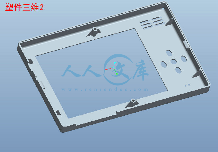
课题申报表.doc

新科MP4上盖模具设计及型腔仿真加工【ProE】【20张CAD图纸+WORD毕业论文】【注塑模具类】

收藏

资源目录
跳过导航链接。
新科MP4上盖模具设计及型腔仿真加工【ProE】【CAD图纸+WORD毕业论文】【注塑模具类】.rar
A3-全套设计-新科MP4上盖模具设计及型腔仿真加工【ProE】
课题申报表.doc---(点击预览)
说明书目录.doc---(点击预览)
说明书正文.doc---(点击预览)
说明书摘要.doc---(点击预览)
说明书封面.doc---(点击预览)
开题报告.doc---(点击预览)
密码-新科MP4上盖模具设计及型腔仿真加工【ProE】.txt---(点击预览)
实习报告.doc---(点击预览)
任务书.doc---(点击预览)
cad插图.doc---(点击预览)
A4-浇口套.dwg---(点击预览)
A4-推板导柱.dwg---(点击预览)
A4-推板导套.dwg---(点击预览)
A4-拉料杆.dwg---(点击预览)
A4-导柱.dwg---(点击预览)
A4-导套.dwg---(点击预览)
A4-定位环.dwg---(点击预览)
A4-复位杆.dwg---(点击预览)
A3-支承板.dwg---(点击预览)
A3-推板.dwg---(点击预览)
A3-推杆固定板.dwg---(点击预览)
A3-定模座板.dwg---(点击预览)
A3-垫块.dwg---(点击预览)
A3-动模座板.dwg---(点击预览)
A3-凹模.dwg---(点击预览)
A3-凸模.dwg---(点击预览)
A3-mp4上盖.dwg---(点击预览)
A1-定模板.dwg---(点击预览)
A1-动模板.dwg---(点击预览)
A0-总装图.dwg---(点击预览)
三维图
a1_format.frm.1
a4_format.frm.1
cavity_1.part.4
cavity_1.prt.1
cavity_1.prt.2
cavity_1.prt.3
cavity_1.prt.5
config.win.1
config.win.2
core_1.prt.1
core_1.prt.2
core_1.prt.3
core_1.prt.4
core_1.prt.5
lifter_1.prt.1
lifter_2.prt.1
lifter_3.prt.1
lifter_4.prt.1
master.prt.1
master.prt.2
master.prt.3
mobile_phone.acc
molding.prt.1
mold_cavity.igs
mold_cavity.prt.1
mold_cavity__out.log.1
mold_core.prt.1
mp4.asm.1
mp4.asm.2
mp4.asm.3
mp4.asm.4
mp4.asm.5
mp4.asm.6
mp4.asm.7
mp4.mfg.1
mp4.mfg.2
mp4.mfg.3
mp4.mfg.4
mp4.mfg.5
mp4.prt.1
mp4.prt.10
mp4.prt.2
mp4.prt.3
mp4.prt.4
mp4.prt.5
mp4.prt.6
mp4.prt.7
mp4.prt.8
mp4.prt.9
mp4_1.asm.1
mp4_1.asm.2
mp4_1.asm.3
mp4_1.crc
mp4_1.drw.1
mp4_1.rep.1
mp4_a_plate1.drw.1
mp4_a_plate1.drw.2
mp4_a_plate1.prt.1
mp4_a_plate1.prt.2
mp4_bush02.prt.1
mp4_b_plate1.drw.1
mp4_b_plate1.drw.2
mp4_b_plate1.prt.1
mp4_b_plate1.prt.2
mp4_ejbpl_mh1.drw.1
mp4_ejbpl_mh1.drw.2
mp4_ejbpl_mh1.prt.1
mp4_ejepl_mh1.drw.1
mp4_ejepl_mh1.drw.2
mp4_ejepl_mh1.prt.1
mp4_ejepl_mh1.prt.2
mp4_ejp_bush03.prt.1
mp4_ejp_pillar04.prt.1
mp4_epincyl000.prt.1
mp4_epinsle300.prt.1
mp4_housing_1.drw.1
mp4_housing_1.drw.2
mp4_housing_1.prt.1
mp4_interlock_fh.prt.1
mp4_interlock_mh.prt.1
mp4_intpl_mh_1.drw.1
mp4_intpl_mh_1.drw.2
mp4_intpl_mh_1.prt.1
mp4_intpl_mh_1.prt.2
mp4_lifter_asm01.asm.1
mp4_lifter_asm02.asm.1
mp4_lifter_asm03.asm.1
mp4_lifter_asm03.asm.2
mp4_lifter_bar03.prt.1
mp4_lifter_guide03.prt.1
mp4_lifter_ret03.prt.1
mp4_lifter_ucoup03.prt.1
mp4_loc_fh7.prt.1
mp4_nipple09.prt.1
mp4_o_ring05.prt.1
mp4_pillar01.prt.1
mp4_pipeplug01.prt.1
mp4_ref_4.prt.1
mp4_ref_4.prt.2
mp4_ref_4.prt.3
mp4_ref_4.prt.4
mp4_risers_mh1.drw.1
mp4_risers_mh1.drw.2
mp4_risers_mh1.prt.1
mp4_screw01.prt.1
mp4_screw02.prt.1
mp4_screw02.prt.2
mp4_screw03.prt.1
mp4_screw05.prt.1
mp4_screw05.prt.2
mp4_screw08.prt.1
mp4_screw09.prt.1
mp4_screw10.prt.1
mp4_sprbush1001.prt.1
mp4_spring_r01.prt.1
mp4_stopdisc01.prt.1
mp4_supbush.prt.1
mp4_topclplate1.drw.1
mp4_topclplate1.drw.2
mp4_topclplate1.prt.2
mp4_topclplate1.prt.3
mp4_topclplate1.prt.4
mp4_wrk_1.prt.1
mp4_wrk_1.prt.2
part_format.frm.1
std.out
trail.txt.21
trail.txt.22
trail.txt.23
trail.txt.24
trail.txt.25
trail.txt.26
trail.txt.27
trail.txt.28
trail.txt.29
trail.txt.3
trail.txt.30
trail.txt.31
trail.txt.32
trail.txt.33
trail.txt.34
trail.txt.35
trail.txt.36
trail.txt.37
trail.txt.38
trail.txt.39
trail.txt.4
trail.txt.40
trail.txt.41
trail.txt.42
trail.txt.43
trail.txt.44
trail.txt.45
trail.txt.46
trail.txt.47
trail.txt.48
trail.txt.49
trail.txt.5
trail.txt.50
trail.txt.51
trail.txt.52
trail.txt.53
trail.txt.54
trail.txt.55
trail.txt.56
trail.txt.57
trail.txt.58
trail.txt.59
trail.txt.6
trail.txt.7
trail.txt.8
trail.txt.9
三维截图
仿真加工截图
外文翻译
工艺卡片
数控仿真加工
cavity_1.elt
cavity_1.elt.bac
cavity_1.igs
数控仿真.elt
程序.TP_UCS11.DEMO
文献资料
acaddoc.lsp
压缩包内文档预览:
预览图
编号:438596    类型:共享资源    大小:36.91MB    格式:RAR    上传时间:2015-06-03 上传人:好资料QQ****51605 IP属地:江苏
45
积分
关 键 词:
新科 mp4 模具设计 仿真 加工 proe cad 图纸 word 毕业论文 注塑 模具
资源描述:

新科MP4上盖模具设计及型腔仿真加工

摘要:本课题是关于MP4上盖模具设计及型腔仿真加工。通过运用模具设计基础和PRO/E、AutoCAD等这些课程的知识去做一次模具设计的实践,并在这次实践中锻炼自己用理论知识来解决实际问题的能力。

本次模具设计主要是对MP4上盖注射成型模的结构设计和模具加工制造。前者包括分型面、型腔布置、浇注系统、排气系统、加热冷却系统、抽芯机构、顶出机构、脱模机构以及主要零部件的设计。后者运用PRO/E进行三维造型设计并对注塑模模具进行装配,对MP4上盖模具定模板型腔的加工工艺进行了分析,并利用MASTERCAM软件进行了仿真加工,其切削过程直观,切削参数得以体现,不合理的参数可以改进,能最大限度地降低能源和材料消耗,提高加工效率。经生产验证,该模具结构设计巧妙、操作方面、使用寿命长、塑件达到技术要求。

关键词:MP4;PRO/E;AutoCAD;注塑模具;模具设计


Tne design of the roof of new MP4 mould And

The simulation processing of the mold cavity

Abstract :This topic is to design the above of MP4 mold design and process simulation process of the cavity. Through use the foundation of design and Proe, AutoCAD such as the knowledge to do the work of these courses a mold design practice, and practice in this exercise with their theoretical knowledge to solve practical problems.

The mold design mainly cover the structure design mould assist designing for manufacturing, and the working process of the injection mould of the roof of the      MP4  were introduced. The former involve parting plane, cavity layout, old systems, heating cooling systems, the core pulling mechanism structure, prop up the organization, drawing patterns and the design process of the main work pieces. The later use Proe to construct carries on the three dimensional modeling and to assemble the injection mould. The processing craft of the cavity of fixed plate of the base of the mp4 are analyzed, and the simulation process are carry out with the software of MasterCAM,which can observe the geometric figure of the process of cutting very visually, the machine parameters users setting have been fully reflected to improve the unreasonable parameters, to minimize consumption of energy and materials and to improve processing efficiency. The mould was proved to be a clever design by production practice , the mould could be operated easily , the service life of the mould was long or and the plastics parts produced by the mould could meet the technical requirement.

Keywords: MP4;PRO / E;AutoCAD;injection mold; mold design


目录

1 前言1

1.1 课题背景1

1.2 本产品特点1

1.3 播放器的主要功能1

1.4 课题意义1

1.5 设计前提及主要问题2

1.6预期成果和实际价值2

2总体方案论证3

3 造型设计4

3.1 产品主要尺寸的确定4

3.2 MP4的造型方法与步骤5

3.3 MP4上壳的造型过程5

4 材料的选择8

4.1塑料的基本概念8

4.1.1塑料的定义及组成8

4.1.2组成8

4.1.3 辅助材料8

4.2 制品材料8

4.3 影响聚合物取向的主要因素(以注射成型为例)8

4.3.1 温度的影响8

4.3.2 注射压力和保压压力9

4.3.3 浇口冻结时间9

4.3.4模具温度9

4.4 常用塑料分析和数据选取9

4.4.1 根据以下表格和结合实际情况选取数据9

4.4.2模具材料的选择10

5 模具设计11

5.1 注塑机的校核11

5.1.1注塑机设备的确定11

5.1.2注塑机有关工艺参数的校核11

5.2分型面的设计13

5.3浇注系统的设计14

5.3.1浇注系统的设计原则14

5.3.2主流道的设计14

5.3.3分流道及其平衡布置14

5.3.4 浇口的设计15

5.3.5 冷料穴的设计15

5.4 冷却系统的设计16

5.4.1在设计冷却系统时,应从多方面考虑:16

5.4.2 冷却计算16

5.5 顶出系统的设计17

5.5.1 推出机构设计17

5.5.2 顶出行程17

5.5.3 复位杆17

5.5.4 顶出杆的形状和尺寸选择18

5.5.5 导向装置位置的布置18

5.5.6 浇注系统零件的设计18

5.6 模架的设计19

5.7凹凸模的造型19

5.8 型腔加工工艺分析及加工仿真23

5.8.1零件的工艺审查23

5.8.2 毛坯选择23

5.8.3 拟定加工方案23

5.8.4 型腔数控仿真加工23

6 结论26

参考文献27

致   谢28

附录29


1 前言

1.1 课题背景

  我的专业是数字化制造,在学习和实习中常常接触很多的数码产品,包括随身听、CD机、DVD机、MP4播放器、翻译机等等。我选择设计MP4播放器上盖。这样有利于我的设计与实践更加紧密结合。

1.2 本产品的特点

(1) 结构简单,但功能强大,实用性强,

(2) 体积小巧携带方便,

(3) 显示屏大,大大提高其可观性,

(4) 其功能键为圆形,美观实用且按键舒适。

1.3 播放器的主要功能

(1)一般具有可视化功能,

   (2)相同的空间能存储更多的信息,

    (3) 不存在防震问题,更加适合运动时欣赏音乐,

    (4) 能随心所欲编辑自己喜爱的歌。

1.4 课题意义

模具是工业生产的重要工艺设备,它被用来成型具有一定形状和尺寸的各种

制品。在各种材料加工工业中广泛地使用各种模具,每种材料成型模具按成型方

法不同又分为若干种类型。其中塑料模具的发展是随着塑料工业的发展而发展

的。近年来,人们对各种设备和用品轻量化要求越来越高,这就为塑料制品提供

了更为广阔的市场。塑料制品要发展,必然要求塑料模具随之发展。模具作为发

展新产品的重要装备,不仅市场需要量大,而且技术含量高。对于模具的精度、

寿命、交货期等要求也非常务实,模具行业的竞争也非常激烈。本课题是MP4上盖制品进行测绘、模具设计、模具型腔仿真加工及数控编程。课题来源于生产实践。基于生产实践之上的对MP4上盖制品的模具设计以及仿真加工。在设计过程中要解决MP4上盖制品测绘、模具设计、在模具设计时对分型面的选择、浇口形式与位置的确定、型腔位置的安排、定模冷却水道的设置、工艺分析及数控编程及加工仿真等问题。本专业是机械设计制造及其自动化,对制品的模具设计使得我们把以前所学的相关知识都运用到其中了,对模具设计手册、机械设计手册、模具制造工艺、中国模具工程大典的查找使得我对设计有了更进一步的认识和了解,能熟练运用PRP/E软件进行制品的造型和模具的装配,还有Mastercam型腔的仿真加工都得到了掌握。


内容简介:
目录1. mp4(制品)12.凹模23.导套34.垫块45.导柱56.复位杆67.浇口套78.顶杆89定模板910定模座板1011动模板1112动模座板1213凸模1314推板1415推板固定板1516支撑板1617.总装图11718.总装图2181制品图2凹模3导套4 垫块5导柱6复位杆7浇口套8顶杆9定模板10定模座板11动模板12动模座板13凸模14推板15推板固定板16支撑板17总装图118总装图2 毕 业 设 计 模具零件三维造型卡片专 业 机械设计制造及其自动化 学生姓名 王 海 荣 班 级 B 机制051班 学 号 0510110133 指导教师 刘 道 标 完成日期 2009年5月15日 毕业设计型腔加工数控代码新科MP4上盖模具设计及型腔仿真加工专 业 机械设计制造及其自动化 学生姓名 王 海 荣 班 级 B 机制051班 学 号 0510110133 指导教师 刘 道 标 完成日期 2009年5月 30日 外文资料名称:TOWARDS CONTROLLABILITY OFINJECTION MOLDING外文资料出处:1999 ASME International Mechanical Engineering Congress & Exposition附 件: 1.外文资料翻译译文 2.外文原文 指导教师评语: 签名: 年 月 日可控注塑成型的发展趋势David Kazmer ,David Hatch王海荣译摘要:过程控制已被确认为提高稳定性和热塑性的一项重要手段,然而没有一个单一的控制策略或系统设计已被普遍接受。注塑过程是成型系统继续生产有限的热和流动力学的加热聚合物熔体缺陷部件的生产过程。 本文讨论的是一些困难所造成的复杂和分发性质注塑过程。相对于运输和流变对流动和热动力学过程进行了分析。然后,两个新的加工方法被描述为循环流量、压力和热控制。仿真和实验结果表明这些创新的有效性可以增加聚合物加工的一致性和灵活性。关键词:过程控制,成型系统,注塑过程。1 导言 注塑能够产生非常复杂且标准的部件。这个过程包括以下几个阶段:塑料化,注塑,包装,冷却和脱模。在注塑成型及其变种(注射压缩天然气协助成型等)中,热塑性塑料颗粒被输入一个旋转螺钉并融化。随着均匀的熔体收集前的螺丝钉是向前发展的轴向控制,随时间变化的速度,以推动融入一个疏散腔。一旦熔体凝固和成型元件有足够的刚性,模具被打开和部分脱落,周期范围从不到4秒的光盘到超过三分钟的汽车零部件。控制注塑明显挑战的是非线性行为的高分子材料,动力和耦合过程的物理和错综复杂的相互作用模具几何和最终产品的质量属性。订正系统的观点,现代常规注塑过程图中提出的机器参数会显示在左侧的数字和一些常见的成型质量的一部分措施是列于右侧。这个过程分为五个不同的阶段。输出的每个阶段不仅直接决定了下一阶段的初始条件,而且影响最后成型部分的质量。图1 :注塑过程的系统观点 图2 :注塑成型控制的系统图2 工艺开发注塑成型控制如图2所示:在最低级只有机驱动器调节,这种控制将确保机器投入妥善地执行方案(图1 ) 。在第二级为状态变量,如熔体温度和熔体压力的控制,跟踪预先指定的配置文件,这将提供更精确的融化控制状况。在外层一级,调整机投入,通过提供更好的盘末点的质量反馈以提高产品质量的组成部分。 显然自动控制是重要的,它是聚合物状态直接决定了成型零件质量。因此,本文的重点是关闭机器之间的回路参数和聚合物状态。如果实现,这些先进的控制策略将提高成型零件的质量和一致性。3 模腔压力控制模腔压力是可以规定成型周期的一个基本状态变量。闭环控制的模腔压力可以自动补偿不同的熔体喷油压力,以实现一致的过程和一套统一的产品属性。曼恩推出的第一个压力控制计划用调制泄压阀 ,并制定了有关反应开环扰动的阿布法拉过程控制模型的模腔压力 。斯里尼瓦桑以后使用这些模式提出了学习控制器闭环腔压力控制。为适应控制方法还提出了在模具中跟踪腔压力通常分布在一个地点 。不幸的是模腔压力控制因缺少一个系统的方法来确定压力。此外,由于没有适当驱动器控制压力,所以它是不完整的。因为传统的注塑机都只配备了一个驱动器(螺钉)不允许同时控制多个点的模腔压力。熔体运输系统在常规冷流道模具如图3所示,很明显几何是“硬线”入模。其次位置是固定的,尺寸也被修复。图3 :典型包装压力分布在可控的注塑成型过程中,进行实验设计,以确定关键的工艺参数和部分尺寸:公式中机器参数从0缩减到1 ,表明了可行的最高加工范围。由此产生的线性模型的系数改变零件实际尺寸。应当指出的是,一次加工完成后,虽然功能显著但尺寸变化可通过处理却十分有限。Nam suh的公理设计指出“应保持独立功能”它适用于开发控制多种自由度熔体流动和模腔压力。图4所示阀门熔体的流动从入口到型腔压降和流速熔体动态多样性,熔体控制在每门可以覆盖影响成型机并提供更好的响应时间和融化的差别控制。每个阀门作为独立注射单位减少依赖于机器的动力。本实施不仅能提供更低的成本和更高的可靠性,而且还继承了传统的外观系统。 图4 :动态流量调节设计 图5 :动态流量调节设计 由此产生的可控注塑成型过程中如图5有多个压力概况可以保持在型腔一个组成部分。在同一周期内,三种不同程度的熔体施加了压力。该压力控制阶段,1号门是41.4兆帕(6000磅),2号门是41.4兆帕(6000磅),3号门是20.7兆帕(3000磅)和4号门是62.1兆帕(9000磅)。在传统的注塑成型中熔体压力将是相同的所有大门。 由上式知有两大影响因素:首先 闭环控制腔压力,大大减少了零件尺寸依赖于机器的设置,并且减少多个零件尺寸标准偏差的5倍,从而增加了过程能力指数,从不到1到远远超出2 。第二如公式改善所提供的三维可控性的动态调节腔压力分布。一般情况下,改变了在门口最接近的模腔压力影响零件尺寸。此外,独立的控制阀产生提供了不同层面的能力在一个地点同时又不干预层面另一地点。应当指出的是,总规模可三维变化的动态压力调节是大致相同的常规成型。这些结论对产品和加工的发展进程可能有重大影响。目前,充型数值模拟和专家判断相结合估计这一进程的行为关键的是设计决策。改进可控的注塑成型过程中允许改正错误,许多设计在模具调试阶段没有重组。这种变化在发展过程中可能大幅度减少工具的开发成本,缩短开发周期,并加快产品上市时间。4 温度控制典型的热路径在冷却阶段的注射成型模具是热量进行热聚合物的相对冷却,然后通过模具的冷却线。虽然动态压力控制已经证明是可行的,并正在商业化。冷却阶段注塑周期是不理想的,很多原因影响了产品质量和生产经济学。物理过程的模具温度必须低于聚合物热变形温度,例如,一个刚性部分弹出。然而,冷却的模具温度进行热量发展造成皮肤外观的一部分和繁殖的冷冻层实现的核心部分。这些冰冻层的流动阻力增加,使模具型腔难以填补。由于冻结层的不断发展,在注射液和冷却不同程度的压力和聚合物形态的变化作为一个功能的厚度减少了光学、结构、性能和其他部分。 目前的研究目标是开发一种新的更具实力的模具壁温动态控制方法。应该使高模壁温度在注射和包装阶段,以促进聚合物的流动,随后引起低模壁温度,以促进凝固的成型部分。最理想的是,在填充过程中模具壁温应与熔体温度平衡。这种模具温度在成型周期尚未实现。动态温度控制有三个主要优点: 1 、更高质量的零件:在注聚合物时提高模具温度可以完全避免发展外皮肤和冰冻层。压力和热梯度部分将减少到最低限度,从而降低双折射,低残余应力等。 2 、减少壁厚:在注聚合物时维持一个高模具温度,流量电导将大大增加,这将能够大幅度减少壁厚。 3 、缩短周期:通过在冷却阶段减少模具壁温,部分更迅速地巩固,生产力得到很大的提高。此外,气温较低的弹射将大大减少后成型收缩从而减少了多方面的变化。目前的办法包括三个简单的概念图6所示。首先,与传统注塑成型相比模具冷却液维持在较低的温度比通常是可行的。其次,重要的是温度瞬时异型模具钢在开始前注射液对流加热的天然气,通过表面的模具根据已知的时间/温度/流量的资料。最后,成型周期的开始与传热动态程序“开环” ,以获取所需的动态模具壁温行为作为时间函数。为提供准确代表性的进程, 20个成型周期的热模拟的前一个周期结果是下一个周期的初始条件的。如果有模具一直在稳态运行生产。这将允许估计整个模具在开始的周期温度分布。 常规 动态冷却 图6 :动态冷却控制 图7 :通过截面零件及模具的温度由此产生的温度分布通过截面聚合物(阴影区)和模具绘制的大量时间如图7,微量 0表明聚合物注入模具的最初温度曲线。在传统的过程中,模具是在低温时注射,造成聚合物100差别的皮肤和核心。在拟议过程中,热瞬时启动,以提供高模具表面温度。改变气体温度和时间的接触可以修改初始温度分布。随后曲线代表温度分布在一秒钟的间隔,冷却期间注塑模具墙将导致流动阻力增加和减少的部分财产,而降低热冷却的模具是传热冷却过程中的一部分,减少了模具冷却温度显著提高了换热冷却,这是减少周期时间所必须的。拟议的进程提供了最低限度的热瞬态期间注射,但仍得以迅速冷却以后的部分。热梯度图7至关重要的是预测和控制其他进程的动态和随后的部分属性。例如,理想的是增加流动电导以减少所需的注射压力。这将不仅使制造更大的部分给指定的机器的能力,而且还增加了部分的统一属性。鉴于流变和热性能的聚碳酸酯,由此产生的压力等值线从中央到边缘的光盘中显示如图8的压力分布在年底充型的代表是坚实的痕迹。装载过程中,高流量和流动阻力将会造成大量的注射压力以填补型腔。图8所示,传统的成型需要大约1的压力以填补模具。拟议的进程使近等温填补模具减少了注射压力到12Mpa。这减少了喷油压力需要较少的能源生产,并增加了标准零件的质量。常规 动态冷却图8 :径向压力等值线光盘热和压力的重要意义如图7和8还可以审查输出部分属性。例如我们会考虑双折射,这是所造成的光学性质变化,两个或两个以上的不同传播速度,同时通过光盘,某一等级的聚碳酸酯,折射指数直接相关的具体数量的模塑部分。图9显示截面各地的具体数量,并通过光盘上弹射。纵坐标轴代表的径向方向而横坐标代表厚度方向。该图已被设置为同样的规模,并可能直接比较。在传统的成型中凝固层的一个重要发展附近(中心部分)已被冻结在高注射压力和包装。腔压力外半径一部分是明显低于在结束包装阶段和整个冷却阶段这两种情况。 常规 动态冷却图9 :比容截面的光盘图 9也显示了可控热瞬态潜在质量的实现。由于模具填补等温条件下,没有凝固层开发一直到包装阶段模腔压力均匀整个腔。这种一致性将使以前没有实现的表面复制,低双折射,和三维属性得以实现。具体的数量几乎是不断跨越半径的光盘通过前30 的厚度,这是关键的地区,后来是扫描。5 结论本文讨论了研究战略,以获得可控的注塑成型过程。所描述的是强大引擎过程的成型行业。压力控制使空间解耦增加自由度的管理质量属性。动态温度控制使颞解耦注射和凝固阶段的进程性能提高。因此,潜在的生产率和质量收益得到巨大的提高事先和正在进行的研究、制造给我们更广泛的研究提供坚实的成功例子,以激励和鼓舞了类似的项目以外的聚合物加工。虽然这种方法目前不存在在实践中,但我们相信,一个严格的设计方法是可以实现的。 这种制造工艺的设计可以提供突破性的竞争优势。最近的研究制造和设计过于集中性和一致性。工业继续降低其研究项目的优先次序,并提供全新的工艺技术。这是学术界的责任和机会,也是更大的风险。致谢这项工作是通过资助期间1992 2002年通过(顺序)通用电气塑料, Dynisco仪器,斯坦福大学集成制造协会,科纳公司,美国能源部的创新工艺方案,国家科学基金会司设计,制造和工业创新,惠普公司,美国美国海军研究办公室。8 1 Copyright 1999 by ASME Proceedings of Materials Processing Symposium: 1999 ASME International Mechanical Engineering Congress & Exposition November 14-19, 1999, Nashville, Tennessee TOWARDS CONTROLLABILITY OF INJECTION MOLDING David Kazmer Department of Mech. & Ind. Engineering University of Massachusetts Amherst David Hatch Department of Mech. & Ind. Engineering University of Massachusetts Amherst ABSTRACT Process control has been recognized as an important means of improving the performance and consistency of thermoplastic parts. However, no single control strategy or system design has been universally accepted, and molding systems continue to produce defective components during production. The capability of the injection molding process is limited by the thermal and flow dynamics of the heated polymer melt. This paper discusses some of the difficulties posed by complex and distributed nature of the injection molding process. The flow and thermal dynamics of the process are analyzed with respect to transport and rheology. Then, two novel processing methods are described to enable in-cycle flow, pressure, and thermal control. Simulation and experimental results demonstrate effectiveness of these innovations to increase the consistency and flexibility in polymer processing. Such system design changes simplify the requisite control structures while improving the process robustness and productivity. INTRODUCTION Injection molding is capable of producing very complex components to tight specifications. The process consists of several stages: plastication, injection, packing, cooling, and ejection. In injection molding and its variants (coinjection, injection compression, gas assist molding, etc.), thermoplastic pellets are fed into a rotating screw and melted. With a homogeneous melt collected in front of the screw, the screw is moved forward axially at a controlled, time-varying velocity to drive the melt into an evacuated cavity. Once the melt is solidified and the molded component is sufficiently rigid to be removed, the mold is opened and the part is ejected while the next cycles thermoplastic melt is plasticized by the screw. Cycle times range from less than four seconds for compact discs to more than three minutes for automotive components. Control of injection molding is significantly challenged by the nonlinear behavior of the polymeric materials, dynamic and coupled process physics, and convoluted interactions between the mold geometry and final product quality attributes. A revised systems view of the modern conventional injection molding process 1 is presented in Fig. 1. The machine parameters are indicated on the left side of the figure, and some common molded part measures of quality are listed on the right. In this figure, the process is decomposed into five distinct but coupled stages. The output of each stage not only directly determines the initial conditions of the next stage, but also influences some of the final qualities of the molded part. Barrel Temp1000PLASTICATIONINJECTIONPACKINGCOOLINGEJECTIONPROCESS/PART QUALITYMelt PressureThermoplasticPelletsScrew Pres0.02Screw RPM0.5DistortionDimensionsClarityEconomicsResid.StressIntegrityEjected PartRelaxationSolidified Layer DevelopmentStrengthAppearanceResidence TimeMelt VolumeMelt TempMelt QualityInjection Velocity Profile0.02Maximum Injection Pressure0.1Packing Pressure Profile0.2Packing Time0.01Melt ViscosityInlet PressureFlow RateMold Coolant Temperature200Cooling Time0.01Melt Front VelocityMelt PresMelt DensityMelt TempSolidified Layer DevelopmentClamp TonnageSolidified Layer DevelopmentCycle TimePart TempPart StrainPart StressEjection Stroke0.02Ejection Velocity0.01FlashMold FailureShot Size0.02MACHINEINPUTSQUALITYATTRIBUTESSTATE VARIABLES Figure 1: Systems view of the injection molding process Thin cavity filling of polymer melt corresponds to creeping flow (Re1) surrounding a hot core region 2. As an example, consider a reference velocity of 10 cm/sec, reference thickness of 3 mm, and a viscosity of 100 Pa Seconds. The Reynolds number based on this case is very small, (10-3), indicating the validity of the highly viscous creeping flow assumption. Furthermore, the flow regions are considered fully developed, and both the unsteady and the gravitational force effects can be ignored due to negligible local acceleration. On the other hand, the thermal diffusivity, 2 Copyright 1999 by ASME ?=k/?Cp, of typical polymer melts is (10-3) cm3/sec, and the kinematic viscosity, ?= /?=103 cm2/sec; hence, the Prandtl number is about (106) and Peclet number, Pe= Re*Pr, is (103). Using these assumptions, the mass, momentum, and energy equations reduce to the following forms in the Cartesian coordinate system: ()()0=+wzvxt (1) xPzvz= (2) 222&+=+zTkxTvtTCp (3) where z and x are the thickness and streamwise directions; v is the velocity component; P is the pressure; is the shear viscosity; , Cp, and k are the thermal properties; &is the shear rate, and 2& is the viscous heating term. The solution of the pressure field in injection molding is obtained by coupling the mass and momentum equations. Generally, the m ass equation provides a convergence criterion for flow rate about which the momentum equation is iteratively solved to produce an accurate pressure field. For each instant of time, all the nodal pressures on the mesh are solved simultaneously. Iteration is required to update the shear rate, viscosity, and flow rate estimates until full convergence is achieved. For a compressible flow, the net mass flux must equal any mass gains or losses within the element 3. The necessary system of equations can be developed, assembled, and solved using a conventional Galerkin formulation for a fixed mesh and transient melt front. Such a simulation has been developed, and will be utilized in assessing strategies for process development along with experimental validation. PROCESS DEVELOPMENT An overview of injection molding control is shown in Fig. 2. At the innermost level, only the machine actuators are regulated. This level of control will ensure proper execution of the programmed machine inputs (Fig. 1). At the second level, state variables such as melt temperature and melt pressure are controlled to track pre-specified profiles. This will provide more precise control of the state of the melt. At the outermost level, the machine inputs are adjusted to improve the quality of the part through better set points given quality feedback. MachineActuatorsProcessMachineControlSetPointControlStateVariableControlMachineFeedbackQualityFeedbackStateVariableFeedbackPartAttributesMachineInputs Figure 2: System diagram of injection molding control While machine control is important, it is the polymer state (pressure, temperature, and morphology) which directly determines the molded part quality 4, 5. As such, this paper focuses on closing the loop between the machine parameters and the polymer state. If achieved, these advanced control strategies would provide increased molded part quality and consistency. Cavity Pressure Control A fundamental state variable that can be regulated during the molding cycle is cavity pressure. Closed-loop control of cavity pressure could automatically compensate for variations in melt viscosity and injection pressure to achieve a consistent process and uniform set of product attributes 6. Mann introduced one of the first pressure control schemes by using modulated pressure relief valves 7, and Abu Fara developed a process control model by relating the cavity pressure response to open-loop perturbations 8. Srinivasan later used these models to propose a learning controller for closed-loop cavity pressure control 9. Adaptive control methods have also been proposed to track cavity pressure profile at usually one location in the mold 10-12. Unfortunately, cavity pressure control suffers from the lack of a systematic method of determining the pressure profile. In addition, it is handicapped by the absence of appropriate actuators for distributed pressure control, as conventional molding machines are equipped with only one actuator (the screw) which does not allow simultaneous cavity pressure control at multiple points in the mold. Consider the melt transport system in a conventional cold runner mold as shown in Fig. 3. It is evident that the geometry is “hard-wired” into the mold. The runner locations are fixed and the gate dimensions are also fixed. The resulting pressure distribution can not be controlled without re-tooling mold steel. Figure 3: Typical Packing Pressure Distribution To investigate the controllability of the injection molding process, a half-factorial design of experiments 13 was performed to determine the main effects between the critical process parameters and the part dimensions: 3 Copyright 1999 by ASME =ScrewSpeedeTemperaturVelocityPressureLLL10. 018. 005. 023. 000. 029. 018. 051. 002. 043. 010. 057. 0321 (4) In this equation, the machine parameters have been scaled to the range of 0 to 1, indicative of the maximum feasible processing range for this application. The resulting coefficients of the linear model are actual change in part dimensions measured in mm. It should be noted that once tooling is completed, the dimensional changes available through processing are quite limited though functionally significant. The primary conclusion that should be drawn from eq. (4), however, is that all the dimensions react similarly to changes in the process settings. Thus, the molding process behaves as a one degree of freedom process in which only one quality attribute is controllable. One of Nam Suhs axioms 14 of design states that “independence of functional requirements should be maintained.” This axiom was applied to develop multiple degrees of freedom for control of melt flow and pressure in the mold cavity. As shown in Fig. 4, the valves meter the flow of melt from the runners into the mold cavity. The pressure drop and flow rate of the melt is dynamically varied by the axial movement of each valve stem which controls the gap between the valve stem and the mold wall. By de-coupling the control of the melt at different valve stem positions, melt control at each gate can override the effects of the molding machine and provide better time response and differential control of the melt. Each valve acts as an individual injection unit, lessening dependency on machine dynamics. For closed loop control, manifold pressure transducers were used in the runner drops instead of in the cavity. This implementation not only provides lower cost and greater reliability, but also renders a conventional appearance for the system. Melt InletValve 1Valve 2Cavity 1Cavity 2P1P2 Figure 4: Dynamic Flow Regulation Design The resulting controllability of the injection molding process is demonstrated in Fig. 5 where multiple pressure profiles can be maintained in the mold cavity of a single part. In the same cycle, three different magnitudes of melt pressure were exerted at different gates in the same mold cavity. The control pressure for the holding stage at Gate 1 is 41.4 MPa (6000 psi.), Gate 2 is 41.4 MPa (6000 psi.), Gate 3 is 20.7 MPa (3000 psi.), and Gate 4 is 62.1 MPa (9000 psi.). In conventional injection molding, the melt pressure would be the same at all gates. This level of process control has not previously been achieved by any molding technology thus far. Each gate can exert a specific holding pressure. 010203040506070024681012Time (sec) Figure 5: Dynamic Flow Regulation Design The material shrinkage and dimensions change at differing locations in the part based on the pressure contours a nd histories around the gates. The ability to change individual dimensions or other quality attributes without re-tooling mold steel provides significant process flexibility. It is possible to augment eq. (4) with the additional degrees of freedom and re-examine the controllability of the three part dimensions: +=P4P3P2P1ScrewSpeedeTemperaturVelocityPressureL3L2L121. 000. 002. 000. 016. 000. 017. 010. 000. 060. 031. 000. 001. 003. 002. 001. 000. 005. 009. 003. 001. 008. 005. 002. 0 (5) There are two significant implications of this result. First, the closed loop control of cavity pressures has significantly reduced the dependence of part dimensions on machine settings, as evidenced by the reduction in the magnitude of coefficients for the primary machine settings. This effect has also been evidenced by reductions in the standard deviations of multiple part dimensions by an average factor of five, resulting in an increase in the process capability index, Cp, from less than 1 to far beyond 2. Second, the second matrix in eq. (5) is evidence of the improved dimensional controllability provided by the dynamic regulation of the cavity pressure distribution. In general, changing the cavity pressure at the gate closest to a dimension provides the major effect on part dimensions. Additionally, independent control of the valve stems provides the capability to vary dimensions at one location without interfering with dimensions at another location. This flexibility does not exist in 4 Copyright 1999 by ASME conventional molding because hold pressure changes intended to influence one area of the part can be transmitted to other areas of the part through the static feed system. It should be noted, however, that the total magnitude of dimensional change available with dynamic pressure regulation is approximately the same as for conventional molding. These results may have a significant impact on the product and tooling development process. Currently, numerical mold filling simulations and expert judgments are combined to estimate the process behavior and make critical design decisions. If these decisions are incorrect, then tooling modifications may be required. Improved controllability of the injection molding process permits correction for many design inaccuracies during the mold commissioning stage without retooling. Such a change in the development process could substantially reduce the tool development costs, shorten the development cycle, and hasten time to market. The described process is also significant in that it moves polymer control from the molding machine to the mold itself. This reduces the molding machine to a polymeric pump. Variations in injection pressure, flow rates, pack pressures, or pack times are all compensated through dynamic pressure and temperature control. The market repercussions could be significant, as 1) an old machine without closed loop control can provide consistency equal to modern machines, and 2) a mold commissioned on a molding machine in the United States is ensured to produce consistent parts on a molding machine overseas. The mold becomes its own self-contained quality control mechanism. As such, the potential productivity and quality gains are substantial. Temperature Control The typical heat path in the cooling stage of injection molding is that heat is conducted from the hot polymer to the comparatively cold mold, then conducted through the mold to the cooling line, where it is convected away by the coolant. Recent research has attempted to dynamically control the thermal and fluid properties of the melt within the molding cycle. While dynamic pressure control has been proven feasible 15 and is being commercialized, the relatively slow thermal transients have prevented similar gains in thermal management. The cooling stage of injection molding cycle is not ideal for a variety of reasons impacting both the product quality and production economics. The process physics dictate that the mold temperature must be less than the polymer heat deflection temperature such that a rigid part is ejected. However, the cold mold temperature conducts heat from the hot polymer melt to the cold mold during injection causing the development of a skin on the exterior of the part and propagation of frozen layers towards the core of the part. These frozen layers increase the flow resistance, making the mold cavity difficult to fill. Since frozen layers are developed continuously during injection and cooling, they lock in varying levels of stress and orientation. This variation in polymer morphology as a function of thickness reduces optical, structural, and other part properties 16-19. To compensate for the negative effects of cold mold walls, manufacturers may run the mold at higher mold temperatures, higher melt temperatures, higher injection pressures, and higher injection velocities 20, 21. Alternatively, a lower viscosity polymer or higher part wall thickness may be required with cost and/or performance disadvantages. All of these options negatively impact the economics of production. In fact, the economic drivers dictate higher mold temperatures during injection (to allow thin part wall thicknesses and low injection pressures) but lower mold temperatures during cooling (to allow rapid solidification). This optimal mold temperature control strategy is infeasible given current control strategies and material technologies. The size of the mold, together with its high heat capacity and thermal inertia, prevents dynamic closed loop control of the mold surface. This statement is based on objective analysis as well as observation of prior academic and industrial 22-34. For instance, Jansen 35, Chen 36, and other researchers have utilized a thermoelectric device within the mold wall to dynamically heat and cool a portion of the mold. However, the time response of these active control elements is relatively slow, on the order of seconds. Also, there is limited ability to induce a large thermal differential due to the mass and properties of the mold. Alternative researchers 25, 26, 31, 32 utilized thin insulative coatings on the surface of the mold to delay the onset of freezing until after polymer injection. Such coatings did not provide adequate durability, but a similar technique is being successfully utilized behind metallic stampers in production of optical media to reduce the cycle time by 0.2 seconds. On a broader scope, mold inserts with high thermal conductivity 27-29 are being more frequently utilized to increase the rate of heat transfer in thick and/or hot sections of the part. As previously stated, no thermoelectric or other thermal actuator exists which will provide the desired transient mold wall temperature control. Moreover, other passive elements (such as insulators or conductors) can only delay or augment the flow of heat from the polymer melt to the cooling line. It is evidenced from these previous attempts that dynamic closed loop control strategies have been unable to either increase the performance of the molded part or reduce the manufacturing cost. Coatings and inserts approaches which do not use active control elements have proven somewhat effective and are gaining acceptance and penetration in the molding industry. For the plastics industry, any successful technology must require little additional complexity and cost while being sufficient robust for high volume production. The objective of current research is to develop a novel and more capable method for dynamic control of mold wall temperature throughout the injection molding process. The resulting technology should enable high mold wall temperatures during the injection and packing stages to facilitate polymer 5 Copyright 1999 by ASME flow and uniform part properties, but then induce low mold wall temperatures to facilitate solidification of the molded part. Ideally, the mold wall temperature should equal the melt temperature during filling, but equal the room temperature during cooling. Such decoupling of mold temperatures during the molding cycle has not yet been achieved. Dynamic temperature control would enable three primary benefits: 1. Higher quality parts. By increasing the mold temperature during polymer injection, the development of an outer skin and frozen layers will be completely avoided. Pressure and thermal gradients across the part will be minimized, leading to reduced birefringence, low residual stress, etc. 2. Reduced wall thickness. By maintaining a high mold temperature during polymer injection, the flow conductance will be greatly increased. This will allow for drastic wall thickness reductions or fewer gates. 3. Reduced cycle times. By reducing the mold wall temperature during the cooling stage, the part will more quickly solidify, resulting in significant productivity increases. Moreover, lower ejection temperatures will result in significantly less post-molding shrinkage thereby reducing the need for dimension changes. The current approach consists of three simple concepts as shown in Fig. 6. First, the mold coolant is maintained at lower temperatures than would normally be feasible with conventional injection molding. Next, a significant temperature transient is profiled in the mold steel prior to the start of injection by convecting a heated gas across the surface of the mold according to a known time/temperature/flow rate profile. Finally, the molding cycle is begun with the heat transfer dynamics proceeding open loop to obtain the desired dynamic mold wall temperature behavior as a function of time during the molding cycle. Cooling Lines (8)Gas & Polymer Inlet100 C300 C200 C0 CSCALE132TemperatureTimePre-HeatInjectionCooling Figure 6: Dynamic Cooling Control This simple process concept leverages existing practices in the plastics industry to facilitate implementation. For instance, convection of the heated gas facilitates rapid heating of the mold surface but requires gas channels for the heated gas to exit. These gas channels already exist in the vents of all existing injection molds. As another example, consider the energy required removing heat from the mold the existing infrastructure of coolant lines and mold water chillers are sufficient. As such, only a high temperature, high pressure gas supply is needed and even this type of auxiliary equipment is being utilized for gas assisted injection molding. Since experimental work is not complete, the system of equations (1) to (3) have been solved with a tridiagonal solver to provide a temperature profile through the thickness of each flow element for each time step of the flow solution. The viscous flow and heat transfer analyses are thus coupled to provide a non-isothermal, non-Newtonian, compressible simulation of all stages of the injection molding process. This transient process simulation will be utilized to analyze the conventional molding of a 1.2mm thick compact disc molded of neat polycarbonate at a melt temperature of 300C and a mold coolant temperature of 100C. The proposed process will also be modeled with an initial heated mold surface temperature of 260C and a mold coolant temperature of 0C. Other important process parameters such as pack pressure, injection velocity, mold open time, and others have been held constant to mirror the observed production of optical media. To provide an accurate representation of the process, twenty molding cycles were simulated where the thermal result of the previous cycle is the initial condition to the next cycle. This will permit an estimation of the temperature profile throughout the mold at the start of the cycle, as if the mold had been running in steady state production. The resulting temperature distribution through a cross section of the polymer (shaded region) and mold are plotted as significant time events in Fig. 7. Trace #0 indicates the initial temperature profile of the mold when the polymer is injected. In the conventional process, the mold is at low temperatures during injection, causing a 100C differential between the polymer skin and core. In the proposed process, a thermal transient is initiated to provide a high mold surface temperature. Altering the gas temperature and time exposure can modify the initial temperature distribution in the mold. 012345670501 0 01 5 02 0 02 5 03 0 03 5 0D i s t a n c e f r o m C e n t e r l i n e ( m m )T e m p e r a t u r e ( C )012345670501 0 01 5 02 0 02 5 03 0 03 5 0Distance from Centerline (mm)T e m p e r a t u r e ( C )Conventional Dynamic Cooling Figure 7: Temperature through Cross-Section of Part & Mold The subsequent curves represent the temperature distribution at one-second intervals. It is evidenced by these 0 2 3 4 1 0 2 3 4 1 6 Copyright 1999 by ASME graphs that conventional molding has exactly the reverse temperature behavior from what is desired. The cold mold wall during injection will cause increased flow resistance and reduction in part properties while the hot mold coolant reduces the heat transfer during part cooling. Reducing the mold coolant temperature significantly increases the heat transfer during cooling but further reduces the mold wall temperature during injectionthis is necessary for cycle time reduction. The proposed process provides for minimal thermal transients during injection yet still permits rapid subsequent part cooling. The thermal gradients of Fig. 7 are critical to predicting and controlling other process dynamics and subsequent part properties. During injection, for instance, increased flow conductance is desired to reduce the required injection pressure. This will not only allow the manufacture of larger parts given a specified machine capacity, but also increase the uniformity of the part properties. Given the rheological and thermal properties of polycarbonate, the resulting pressure contours from the center to the edge of the compact disc are shown in Fig. 8. The pressure distribution at the end of mold filling is represented by the solid trace. During filling, high flow rates and flow resistance will cause significant injection pressure to fill the mold cavity. As shown in Fig. 8, conventional molding requires approximately 19Mpa pressure to fill the mold. The proposed process enables nearly isothermal filling of the mold with a reduction in the injection pressure to 12 Mpa. This reduction in injection pressure does significantly expand the moldability of the product, requires less energy for manufacture, enables molding of larger parts, and increases the uniformity of the part quality. 010203040506070051015202530R a d i u s ( m m )M e l t P r e s s u r e ( M P a )010203040506070051015202530R a d i u s ( m m )M e l t P r e s s u r e ( M P a )Conventional Dynamic Cooling Figure 8: Radial Pressure Contours across Compact Disc Once the mold cavity is filled with molten polymer, additional melt is forced into the mold cavity at high pressure to compensate for volumetric shrinkage as the frozen layers propagate towards the core of the part. In the manufacture of optical media and lenses, accurate surface replication and low birefringence are desired. The former attribute requires high cavity pressure while the latter attribute requires uniform polymer morphology across and through the part. As shown in Fig. 8 via the dashed lines, both conventional molding and the proposed process provide very uniform radial cavity pressure at the beginning of the packing stage. The significance of the thermal and pressure histories shown in Figs. 7 and 8 can also be understood by examining the output part properties. As an example, we will consider birefringence, which is caused by a variation in optical properties that force light to travel at two or more distinct speeds while propagating through the compact disk. With a given grade of polycarbonate, the index of refraction is directly related to the specific volume of the molded part 37, 38. Fig. 9 displays a cross section of specific volume across and through the optical disc at ejection. The ordinate axis represents the radial direction while the abscissa represents the thickness direction from the mid-plane of the optical disc. The graphs have been set to the same scale and may be compared directly. In conventional molding, a significant solidified layer develops near the gate (center of part) which has frozen during the high injection and packing pressures. The cavity pressure at the outer radius of the part is significantly lower during the end of the packing stage and throughout the cooling stage in both cases. 101520253035404550550102030405060708090R a d i u s ( m m )Distance from Centerline (%)101520253035404550550102030405060708090R a d i u s ( m m )D i s t a n c e f r o m C e n t e r l i n e ( % )Conventional Dynamic Cooling Figure 9: Specific Volume of Cross-Section of Compact Disc Fig. 9 also shows the potential quality improvement should controllability of the thermal transients be achieved. Since the mold is filled at isothermal conditions, no solidified layers develop until the end of the packing stage and the cavity pressure is uniform throughout the cavity. Such uniformity will enable previously unattained surface replication, low birefringence, and dimensional properties. The specific volume is nearly constant across the radius of the compact disc through the first 30% of the thickness, which is the critical area that is later metallicized and scanned. CONCLUSION This paper has discussed research strategies to gain controllability of the injection molding process. The described processes are powerful enablers for the molding industry. Multi-cavity pressure control enables spatial decoupling to increase the number of degrees of freedom governing quality attributes. Dynamic temperature control enables temporal decoupling of the injection and solidification stages to increase the process performance. As such, the potential productivity and quality gains from these processes are substantial. It was our broader intent to provide solid examples of successful prior and on-going research in manufacturing to motivate and inspire similar projects outside of polymer processing. We believe that a rigorous design methodology is attainable based on the foundation provided by the National 7 Copyright 1999 by ASME Research Council, though such a methodology does not currently exist in practice. Such a methodology is based on three fundamental underpinnings: 1. The establishment of quantitative performance attributes with well-defined relationships to economic measurablesto provide a baseline for rationalizing development; 2. Use of simulation and controlled experimentsto investigate theoretical feasibility and establish performance goals; and, 3. Incorporation of modern design methodologiesto provide robust manufacturing processes with tight constraint-based management. Such manufacturing process design can provide breakthroughs for competitive advantage. Recent research in manufacturing and design has overly focused on robustness and consistency. As industry continues to lower its research priorities, it is academes responsibility and opportunity to take greater risks and deliver fundamentally new process technologies. ACKNOWLEDGMENTS This work was funded through the period of 1992 to 2002 through (sequentially) General Electric Plastics, Dynisco Instruments, Stanford University Integrated Manufacturing Association, Kona Corporation, U.S. Department of Energy Innovative Process Program, National Science Foundation Division of Design, Manufacture, and Industrial Innovation, Hewlett-Packard Corporation, and the U.S. Office of Naval Research. REFERENCES 1 C. Y. W. Ma, “A Design Approach to a Computer-Controlled Injection-Molding Machine,” Polymer Engineering and Science, vol. 11, pp. 768-772, 1974. 2 H. S. Lee, “Thin Cavity Filling Analysis Using the Finite Element Method with Control Volume Technique,” in Mechanical Engineering. Troy, NY: Rensselaer Polytechnic Institute, 1989. 3 Hwai Hai Chiang, “Simulation and Verification of Filling and Post-Filling Stages of the Injection Molding Process,” in Mechanical Engineering. Ithaca, NY: Cornell University, 1989. 4 P. D. Coates and R. G. Speight, “Towards intelligent process control of injection moulding of polymers,” Proceedings of the Institution of Mechanical Engineers, Part B: Journal of Engineering Manufacture, vol. 209, pp. 357-367, 1995. 5 R. Dubay, A. C. Bell, and Y. P. Gupta, “Control of plastic melt temperature: A multiple input multiple output model predictive approach,” Polymer Engineering and Science, vol. 37, pp. 1550-1563, 1997. 6 U. Langkamp, “Pressure and temperature sensors,” Kunststoffe Plast Europe, vol. 86, pp. 1804-1812 German, 1996. 7 J. W. Mann, “Process Parameter Control: the Key to Optimization,” Plastics Engineering, vol. 30, pp. 25-27, 1974. 8 M. R. Kamal, W. I. Patterson, N. Conley, D. Abu Fara, and G. Lohfink, “Dynamics and Control of Pressure in the Injection Molding of Thermoplastics,” Polymer Engineering and Science, vol. 27, pp. 1403-1410, 1987. 9 K. Srinivasan and T. Brinivasan, “Learning control of melt pressure in injection molding processes,” presented at American Society of Mechanical Engineers, Dynamic Systems and Control Division (Publication) DSC, Atlanta, GA, USA, 1991. 10 F. Gao, I. A. N. Patterson, and M. R. Kamal, “Self-tuning cavity pressure control of injection molding filling,” Advances in Polymer Technology, vol. 13, pp. 111-120, 1994. 11 C.-P. Chiu, M.-C. Shih, and J.-H. Wei, “Dynamic Modeling of the Mold Filling Process in an Injection Molding Machine,” Polymer Engineering and Science, vol. 31, pp. 1417-1424, 1991. 12 R. E. Nunn and C. P. Grolman, “Closed Loop Cavity Pressure Control in Injection Molding,” J. Reinforced Plastics and Composites, vol. 9, pp. 2121, 1991. 13 J. T. Luftig and V. S. Jordan, Design of experiments in quality engineering. New York: McGraw-Hill, 1998. 14 N. P. Suh, D. R. Wilson, A. C. Bell, F. V. Dyck, and W. W. Tice, “Manufacturing Axioms and their corollaries,” presented at The SME Seventh North American Metalworking Research Conference, 1979. 15 D. O. Kazmer and P. Barkan, “Multi-Cavity Pressure Control in the Filling and Packing Stages of the Injection Molding Process,” Polymer Engineering and Science, vol. 37, pp. 1865-1879, 1997. 16 W. C. Bushko and V. K. Stokes, “Solidification of thermoviscoelastic melts. Part I: Formulation of model problem,” Polymer Engineering and Science, vol. 3
温馨提示:
1: 本站所有资源如无特殊说明,都需要本地电脑安装OFFICE2007和PDF阅读器。图纸软件为CAD,CAXA,PROE,UG,SolidWorks等.压缩文件请下载最新的WinRAR软件解压。
2: 本站的文档不包含任何第三方提供的附件图纸等,如果需要附件,请联系上传者。文件的所有权益归上传用户所有。
3.本站RAR压缩包中若带图纸,网页内容里面会有图纸预览,若没有图纸预览就没有图纸。
4. 未经权益所有人同意不得将文件中的内容挪作商业或盈利用途。
5. 人人文库网仅提供信息存储空间,仅对用户上传内容的表现方式做保护处理,对用户上传分享的文档内容本身不做任何修改或编辑,并不能对任何下载内容负责。
6. 下载文件中如有侵权或不适当内容,请与我们联系,我们立即纠正。
7. 本站不保证下载资源的准确性、安全性和完整性, 同时也不承担用户因使用这些下载资源对自己和他人造成任何形式的伤害或损失。
提示  人人文库网所有资源均是用户自行上传分享,仅供网友学习交流,未经上传用户书面授权,请勿作他用。
关于本文
本文标题:新科MP4上盖模具设计及型腔仿真加工【ProE】【20张CAD图纸+WORD毕业论文】【注塑模具类】
链接地址:https://www.renrendoc.com/p-438596.html

官方联系方式

2:不支持迅雷下载,请使用浏览器下载   
3:不支持QQ浏览器下载,请用其他浏览器   
4:下载后的文档和图纸-无水印   
5:文档经过压缩,下载后原文更清晰   
关于我们 - 网站声明 - 网站地图 - 资源地图 - 友情链接 - 网站客服 - 联系我们

网站客服QQ:2881952447     

copyright@ 2020-2025  renrendoc.com 人人文库版权所有   联系电话:400-852-1180

备案号:蜀ICP备2022000484号-2       经营许可证: 川B2-20220663       公网安备川公网安备: 51019002004831号

本站为文档C2C交易模式,即用户上传的文档直接被用户下载,本站只是中间服务平台,本站所有文档下载所得的收益归上传人(含作者)所有。人人文库网仅提供信息存储空间,仅对用户上传内容的表现方式做保护处理,对上载内容本身不做任何修改或编辑。若文档所含内容侵犯了您的版权或隐私,请立即通知人人文库网,我们立即给予删除!