毕业设计论文.doc

某微型客车后驱动桥设计【6张图纸】【优秀】【Word+CAD图纸全套设计】

收藏

压缩包内文档预览:(预览前20页/共50页)
预览图 预览图 预览图 预览图 预览图 预览图 预览图 预览图 预览图 预览图 预览图 预览图 预览图 预览图 预览图 预览图 预览图 预览图 预览图 预览图
编号:443823    类型:共享资源    大小:1.94MB    格式:ZIP    上传时间:2015-06-26 上传人:小*** IP属地:福建
50
积分
关 键 词:
x0020 微型 客车 驱动 设计
资源描述:

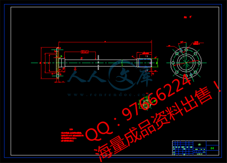
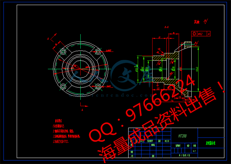
某微型客车后驱动桥设计

摘  要

驱动桥是汽车行驶系统的重要组成部分。其基本功用是增大有传动轴或直接有变速器传来的转矩。并将动力分配给左、右两个驱动轮,使左、右驱动轮具有汽车形式运动学所要求的差速功能。所以其设计质量直接关系到整车性能的好坏。在设计过程中,需要严谨和认真的态度进行设计。

在绪论部分,对本课题的背景研究意义及国内外情况简明扼要的说明。在方案论证部分,对驱动桥及其总成结构形式的选择作了具体的说明。本设计选用了单级减速器,采用的是双曲面齿轮啮合传动,尽量的简化结构,缩减尺寸,有效的利用空间,充分减少材料浪费,减轻整体质量。由于是微型客车,主要行驶在路面较好的条件下,决定使用对称式圆锥行星齿轮差速器。半桥则选用全浮式半桥。在设计计算与强度校核部分,对主减速器、差速器、半轴和驱动桥壳等重要部件的参数作了选择。同时也对以上的几个部件进行了必要的校核计算。

结束语是对本次毕业设计的一些看法和心得体会,并对悉心帮助和指导过我的指导老师和同学表示衷心的感谢和深深的敬意。


关键词: 微型客车;驱动桥;主减速器;差速器

Design of drive axle minibus

Abstract

Drive axle is an important part of the car system. Its basic function is to increase the shaft or directly with the transmission of torque. And distributes power to the left and right two driving wheels, make the left and right driving wheels car form required by the kinematic differential function. So its design quality directly related to vehicle performance is good or bad. In the process of design, need strict and serious attitude to carry on the design.

In the introduction part, the background of this topic research significance and the situation at home and abroad and brief description.Part of the project demonstration, the choice of drive axle and assembly structure forms the specific instructions. This design chooses a single stage reducer, USES a hyperboloid gear meshing transmission, try to simplify the structure, reduced size, effective use of space, sufficient to reduce material waste, reduce the overall quality. Being minivans, main drive under the condition of the pavement better, decided to use the symmetric cone planetary gear differential. A half bridge is semi floating half bridge.In design calculation and intensity, the Lord reducer, differential and half shaft and drive axle housing, and other important components of the parameters has made the choice. And at the same time for more than a few parts for the necessary checking calculation.

Is the conclusion of this graduation design of some of the views and comments, and carefully to help and guidance of my instructor and classmates express my heartfelt thanks and deep respect.


Key words: minivans;drive axle;The main reducer;differential


主 要 符 号 表

大齿轮节锥距

从动锥齿轮中点锥距

轴承的额定动载荷

分别为主、从动双曲面齿轮的外圆直径

分别为主、从动双曲面齿轮的节圆直径

双曲面齿轮偏移距

双曲面齿轮的从动齿轮齿面宽

汽车正常使用时的平均爬坡能力系数

汽车或汽车系列的性能系数

道路滚动阻力系数

后轴对水平地面的荷重

汽车满载总重量

分别为主、从动齿轮的齿顶高

分别为主、从动齿轮的齿根高

齿工作高

齿工作高系数

齿全高系数

驱动桥主减速比

分动器高档传动比

变速器1档传动比

轮边减速器传动比

传动系低档传动比

双曲面齿轮轮齿弯曲计算用综合系数

双曲面齿轮的从动齿轮齿顶高系数

双曲面齿轮强度计算用表面质量系数

双曲面齿轮强度计算用载荷分配系数

双曲面齿轮强度计算用超载系数

双曲面齿轮强度计算用尺寸系数

双曲面齿轮强度计算用质量系数

轴承的额定寿命

齿轮模数、端面模数

发动机最大功率下的转速

发动机最大功率

单位齿长上的圆周力

刀盘的名义半径

车轮的滚动半径

发动机转矩

发动机最大转矩

计算转矩

发动机最大转矩配以传动系最低挡传动比时作用在主减速器从动齿轮上的计算转矩

驱动车轮滑转时作用在主减速器从动齿轮上的计算转矩

主减速器从动齿轮的平均计算转矩

齿轮齿数

齿轮压力角

中点螺旋角或名义螺旋角

分别为双曲面齿轮主、从动齿轮的节锥角

分别为主、从动齿轮的面锥角

分别为主、从动齿轮的根锥角

轮胎与路面的附着系数

汽车传动系效率

轮边减速器的传递效率

接触应力

弯曲应力

扭转应力

      剪切应力


目  录

1 绪论1

1.1题目背景1

1.2研究意义1

1.3国内外相关研究情况1

1.4本设计研究的主要内容3

2 驱动桥总成结构形式及布置4

2.1总体方案论证4

2.2驱动桥的分类4

2.2.1非断开式驱动桥4

3 主减速器设计6

3.1主减速器结构方案的分析6

3.2主减速器主、从动锥齿轮的支承方案8

3.3主减速器锥齿轮设计9

3.3.1主减速比i0的确定9

3.3.2主减速器齿轮计算载荷的确定10

3.4主减速器齿轮基本参数的选择11

3.4.1齿数的选择11

3.4.2从动锥齿轮节圆直径的选择11

3.4.3从动锥齿轮端面模数的选择12

3.4.4螺旋锥齿轮齿宽F的选择12

3.4.5螺旋锥齿轮的螺旋方向12

3.4.6螺旋角的选择12

3.4.7齿轮法向压力角的选择13

3.5主减速器圆弧齿螺旋锥齿轮的几何尺寸计算13

3.6主减速器螺旋锥齿轮的强度计算15

3.6.1单位齿长上的圆周力15

3.6.2轮齿的弯曲强度计算16

3.6.3轮齿的齿面接触强度计算17

3.7主减速器齿轮的材料及热处理17

3.8主减速器轴承的计算18

3.8.1作用在主减速器主动齿轮上的力18

3.8.2主减速器轴承载荷的计算20

3.8.3主减速器轴承额定寿命的计算21

3.9主减速器的润滑22

4 差速器设计24

4.1差速器结构形式的选择24

4.2对称式圆锥行星齿轮差速器的设计25

4.2.1差速器齿轮的基本参数选择25

4.2.2差速器齿轮的几何尺寸计算27

4.3差速器齿轮的材料选择28

4.4差速器齿轮的强度计算28

5 半轴设计30

5.1半轴的型式30

5.2半轴的设计与计算31

5.2.1全浮式半轴计算载荷的确定31

5.2.2全浮式半轴杆部直径的初选31

5.2.3半轴的结构设计、材料与热处理31

5.2.4半轴的强度计算32

6 驱动桥壳体设计34

6.1驱动桥壳的分类34

6.1.1可分式桥壳34

6.1.2整体式桥壳35

6.1.3组合式桥壳36

6.2驱动桥壳的选择36

7 结 论37

参考文献38

致 谢39

毕业设计(论文)知识产权声明40

毕业设计(论文)独创性声明41


内容简介:
毕业设计(论文)中期报告题目: 某微型客车后驱动桥设计系 别 机电信息系 专 业 机械设计制造及其自动化 班 级 姓 名 学 号 导 师 2013 年 03 月 21 日设计(论文)进展状况一 目前已完成以下工作:1.了解轻型货车后驱动桥的工作情况、用途、组成部分及工作原理;2.通过互联网收集设计驱动桥时所需要的数据以及参考资料,初步分析驱动桥结构和设计思路,熟悉课题,提出驱动桥设计方案;3.完成了主减速器的基本参数计算;3.1 主减速比 i0 0max.37rPgHnii3.2 主减速器齿轮计算载荷的确定:通常是将发动机最大转矩配以传动系最低档传动比时和驱动车轮在良好的路面上开始滑转时这两种情况下作用在主减速器从动齿轮上的转矩( 、 )的较小者,作jeTj为载货汽车和越野汽车在强度计算中用以验算主减速器从动齿轮最大应力的计算载荷,即:max0/jeTLiKn2rjBGi得的计算载荷为最大转矩,而不是正常持续转矩,不能用它作为疲劳损坏的依据。但对于公路车辆来说,使用条件较非公路车辆稳定,其正常持续转矩根据所谓平均比牵引力的值来确定,即主减速器从动齿轮的平均计算转矩 为:jmT()()aTrjmRHpLBGffin4.完成了差速器基本参数计算:4.1 差速器齿轮基本参数选择:a. 行星齿轮数目的选择微型客车采用 2 个行星齿轮。b. 行星齿轮球面半径 RB 的确定圆锥行星齿轮差速器的结构尺寸,通常取决于行星齿轮背面的球面半径 ,它BR就是行星齿轮的安装尺寸,实际上也代表了差速器圆锥齿轮的节锥距,因此在一定程度上也表征了差速器的强度。球面半径 可按如下的经验公式确定:BR mm 3BjRKT差速器行星齿轮球面半径 确定后,可根据下式预选其节锥距:mm 0(.98.)BARc. 行星齿轮与半轴齿轮齿数的选择为了获得较大的模数从而使齿轮油较高的强度,应是行星齿轮的齿数尽量少,但一般不应少于 10。半轴齿轮的齿数采用 1425。取半轴齿轮齿数为 20,汽车的半轴齿轮与行星齿轮的齿数比应在 1.52 的范围内,取行星齿轮齿数 =10,满足条1z件。差速器的各个行星齿轮与 2 个半轴齿轮是同时啮合的,因此在确定这两种齿轮的齿数时,应考虑他们之间的装配关系。在任何圆锥行星齿轮式差速器中,左、右两半轴齿轮的齿数 、 之和,必须能被行星齿轮的数目所整除,以便行星齿轮能2LzR均匀的分布于半轴齿轮的轴线周围,否则差速器将无法安装。既满足的条件为:2LzInd. 差速器圆锥齿轮模数及半轴齿轮节圆直径的初步确定首先初步求出行星齿轮及半轴齿轮的节锥角 、12132tanzrc41tz式中:, 分别为行星齿轮和半轴齿轮齿数。1z2再按下式初步求出圆锥齿轮的大端端面模数 m002342sinsiAmZ式中:、 、 以在上面确定; =2.5mm,确定半轴齿轮节圆直径。0A1z222dz代入有: =50mm。2de. 压力角 汽车差速齿轮大都采用压力角 =22 30 ,齿高系数为 0.8 的齿形。f. 行星齿轮安装孔的直径 及其深度L行星齿轮安装孔的直径 与行星齿轮轴的名义直径相同,而行星齿轮安装孔的深度 就是行星齿轮在其轴上的支承长度。通常取L1.L320.cTnlmm 301.cl4.2 差速器齿轮的强度计算差速器齿轮主要进行弯曲强度计算,而面对疲劳寿命则不予考虑,这是因为行星齿轮在差速器的工作中经常只起等臂推力杆的作用,只有左、右驱动车轮有转速差时行星齿轮和半轴齿轮之间才有相对滚动。汽车差速器齿轮的弯曲应力为:MPa 30241smwVTKFZJ式中:差速器一个行星齿轮给予一个半轴齿轮的转矩,Nm;其计算式为:T0.6jTn5.完成了对半轴的设计与计算:5.1 全浮式半轴计算载荷的确定本课题驱动形式采用 4 2 型,全浮式半轴只承受转矩,其计算转矩按下式进行计算:Nm max0egTi5.2 全浮式半轴杆部直径的选定在设计时,全浮式半轴杆部直径的初步选取可按下式进行:mm 333510(2.5.18).96dT5.3 半轴的强度计算计算半轴扭转应力 : 35106Td计算半轴在承受最大转矩时其花键的剪切应力与挤压应力。半轴花键的剪切应力为:MPa 3104sBAPTDdZLb半轴花键的挤压应力为:MPa 31042cBABAPTdZL6.驱动桥壳的设计整体式桥壳因制造方法不同,可分为整体铸造式、中段铸造压入钢管式和钢板冲压焊接式等。本设计选用整体铸造式桥壳,它具有如下优点:可制造成复杂而理想的形状,壁厚能够变化,可得到理想的应力分布,其刚度和强度都比较好,工作可靠,适应于要求桥壳承载负荷较大的中型和重型载货汽车。7.完成了对外文文献的翻译工作;8.完成中期报告,准备中期答辩。 二 存在问题及解决措施存在问题: 由于是在校外设计,有些资料无法查询导致部分计算没有进行,查阅的资料不全面导致部分数据计算有误差,齿轮参数确定的也有误,导致多次进行齿轮的强度校核。没有对轴承进行选择与校核。在计算中也暴露出自己的问题,下一步在这些方面多加努力。解决措施:利用学校的图书资源完善前期设计,认真确认各种参数加强计算方面的不足。三 后期工作安排第 10 周:完成零件设计的计算工作,确定装配图的具体尺寸;第 11 周:完成零件装配图的设计;第 12-13 周:完成全部零件图的设计;第 14-17 周:撰写毕业设计论文;第 18 周:复查、整理材料,准备答辩。注:1. 正文:宋体小四号字,行距 22 磅;标题:加粗 宋体四号字2. 中期报告由各系集中归档保存,不装订入册。指导教师签字:2013 年 3 月 22 日Received 21 February 2007Developmentofa TestMachine for IVECO DriveAxleWANG Liang-mo, WANG H e-fu, CHEN Jin-rong, LING Zhi-liang, CAO Yu-huaSchool ofMechanicalEngineering, NanjingUniversity of Science andTechnology, Nanjing 210094, P. R. ChinaAbstract: To improve the automation level of the vehicle drive axle test and better simulate a vehiclecsactual operation, an advanced testmachine has been developed. The load system of themachine consistsof hand brakes and electric cylinders. It is simple-structured and low-cost. Themajormotor of thema-chine is controlled by a transducer and its speed can be adjusted easily. In addition, the programmedmachine can automatically test such parameters as the grinding condition, the differential speed, thenoise level, etc. It can also adjust the test procedures according to different requirements. Detailed dis-cussion of the structure and mechanism of the testmachine is given in this paper.Key words: vehicle, testmachine, drive axle, IVECO1 IntroductionThe drive axle of a vehicle is composed of a final drive, a differentia,l a shel,l hal-f axles andbrakes, etc. It comes into play at the last transmission stage of the vehicle transmission system. Thegrinding functionality, the transmission stability, the braking capability, and the noise volume,etc., of the drive axlewillallaffect a vehiclecs quality and performance. Therefore, after the driveaxle is assembled, it is necessary to test such functionalities as the grinding, differential speeding,and noise levels, etc.Currently, only a few manufacturers test the functionalities of vehicle drive axles in their domesticassembly lines. In addition, the automation levelof thesemanufacturersc testmachines is relativelylow. For example, theYuejinMotorGroupCorporation uses amanually-operated and single-speeddrive axle testmachine. Thismachinedoes nothave ameasuring system for testing the speed, load,and noise levels. Thus, themachine cannot control its test time accurately. Furthermore, the simu-lated operation deviates quite far from the actualoperation, so that it can not ensure theperformanceand quality of the drive axle.However, the drive axle testmachine of the IVECO vehicle has a relatively high levelof automationand provides some advanced functionalities. It enables abetter simulation of avehiclecs actualoper-ation and also increases the accuracy of the tes.t This paper introduces the advanced functionalitiesof the IVECO testmachineby illustrating themachinecs structure, mechanism, aswell as thedesignfeatures of themachinecsmechanicaland electricalcontrolling system.InternationalJournalofPlantEngineering andManagement Vo.l 12 No. 1 March 20072 The structure andmechanism of the testmachineFigure 1 Illustration of the IVECOcs drive axletestmachineFigure1 illustrates IVECOcs drive axle testma-chine. The testmachine primarily consists of atransmission device, a locating and holding de-vice, a loading device, and an oil intake and re-lease device, etc.( 1) The transmission deviceThe transmission device consists of a drive shaftwith a spline, amovable spline liner, a b-idirec-tionalacting cylinder, universal joints and pegs,etc. The transmission device joins themotorwiththe testdrive axle. This device ispneumatic. V iathe displacement sensor and the programmablecontroller, the transmission device not only canautomatically transmit themotorcs force to the tested drive axle, but also can automatically separatethe two.IVECOcs testmachine for the first timeuses the transducer andhas achieved thestepless speed regu-lation between 0 and 3000 r/min, thus allowing a better simulation of a vehiclecs actual operation.Furthermore, the transm ission deviceworks fas,t easily, and reliablywithoutnoticeable shocks, v-ibrations and noises.( 2) Locating and holding deviceWhen the transmission device and the drive axle are joined, it is required that the axis of the driveshaft be alignedwith the axis of the final gear in order to reduce shocks, vibrations and noises. Tomeet this requiremen,t a locating device is designed for the testmachine. Based on the principle ofcomplete location, the locating device uses threeV-shaped pieces for locating. Among them, twopieces are positionedon the edges of thehal-f axle liner, while the thirdpiece is positionedunder thedrive axle, within the limit of 6 degrees of freedom.During the tes,t the drive axle vibrates violently because of the high speed of the hal-f axle andwheels. To reduce the vibration, a pneumatic board is installed above the two V-shaped pieceswhich are positioned outside the hal-f axle liner, holding the drive axle tightly.( 3) Loading deviceThe drive axle testmachinegenerallyuses the electric eddy currentbrake, or the asynchronous gen-erator, as its loading device. The loading effectswillbe imposedwhen the brake or the generator isjoinedwith the left and rightwheels of the drive axle. This type of testmachines have notable andlasting loading effects, and can perform loading testson thedrive axle fora long time. However, thearrangement of thesemachines is crowded and the cost of thesemachines is also relatively high, be-cause two electric eddy currentbrakes, or two asynchronous generators, willbe added into the testmachines for the loading.25Development ofaTestMachine for IVECO DriveAxleComparedwith the conventional loading device, the loading deviceof IVECOcs testmachine is inno-vative in two aspects. Firs,t itworkswithhandbrakes. Second, it adopts thedomestically newly in-troduced and developed electric cylinders. These cylinders are simple-structured, and their loadscan be easily adjusted. When the loading device isworking, the electric cylinders tighten the handbrakescsteelrope andmove thebrakes. The load levels canbe changedby adjusting themovementsof the hand brakescsteel rope. Concurrently, differential transmissions of thedrive axle can also beachievedwith thehand brakes.( 4) Oil intake and releasedeviceBefore the tes,t kerosene needs to be fed into theoil intakedevice and then themachine is cleaned.After the cleaning, kerosene needs to be released completely and then engine oil is added. Engineoil can be recycled during the tes.tThe critical techniqueof the oil intakedevice is the designof the quick oil intake and release joints.The principles and structures of these two joints are basically the same. During the operation, thecylinder pushes the intake and releasedevice to connectquickly and accurately through a connectingrod. In addition, a special device is also used to ensure the sealing performance of the intake andrelease device.In the oil release system, oil is first released from a releasing hole into an oi-l separating box. Then,through an oi-l separating valve, which is connectedwith the oi-l separating box, kerosene is separa-ted from the engine oi.l3 Controlling systemFigure 2 The controlling system of the testmachineCurrently, there are three types ofwel-ldevelopedme-chanical and electrical controlling systems: the relaycontact controlling system, the programmable contro-lling system, and the industrially-controlled computersystem. The relay controlling system is slow, clumsy,and only allows for simple contro.l The industrially-controlled computer system is expensive, and difficultto program, while the programmable controlling systemis smal,l reliable, wel-l functioned, and easy to pro-gram. Therefore, the programmable controlling systemis selected here for the testmachine. Figure 2 showsthe controlling system of the testmachine.The design procedure of the testmachinecs controllingsystem is as follows:( 1) Analyzing theworkflowsThe drive axlecs testmachine operates in two phases: the preparation and the tes.t The preparationphase proceeds in the sequence of installing thedrive shaf,t connecting the drive axlewith the drive26 InternationalJournalofPlantEngineering andManagement Vo.l 12 No. 1 March 2007shaft, feeding kerosene, rotating the generator clockwise and counter-clockwise ( cleansing the driveaxle) and releasing kerosene through air pressure.The test phase proceeds in the sequence of feeding engine oi,l rotating the generator clockwise, a-lternative loading or simultaneous loadingwith the lefthand brake and right hand brake, differentialand delayed transmission, grinding, measuring noise, rotating the generator counter-clockwise, a-lternative loadingwith the left hand brake and right hand brake, differential and delayed transm is-sion, restoring the lefthand brake and righthandbrake, stopping the generator, testing the oil sea-ling performanceof the oil intake and releasedevice, releasing engine oil throughairpressure, resto-ring the oil intake join,t restoring thedrive shaf,t restoring theholding device to the end of the tes.t( 2) Determ ining the inputbits and output bitsThe input bits prmi arily include the signalof thedrive shaftcs position, the signalof theholding devicecsposition, the signal of the oil intake and release jointscposition, aswell as the signals of the automaticstopping button and stepping button, etc. Altogether, there are53 inputbits. The output bits prmi arilyinclude the start signalof thegenerator, the start signalof each valveof thepneumaticsystem, aswellasthe start signals of the electric cylinders, etc. Altogether, there are 33 output bits.( 3) Selecting the program controllerCurrently, there aremany types ofprogram controllers. In terms of theirbitnumbers and functiona-lities, they can be classified into three categories: smal-l sized, medium-sized, and large-sized. Thesmal-lsized controlling system is selectedheremostly for the purpose ofproducing suchon-off actionsas sequential controlling, time controlling andwarning and locking, etc. The totalnumber of inputand output bits is 86. Mitsubishics F1 series of programmable controllers are used, with a 60-bitmain engineF1-60MR and a40-bitextended engineF1-40ER. Altogether, they generate100 inputand output bits, with amargin of14 bits.( 4) Drawing the inputandoutput terminaldistributionchartanddefining each inputandoutputnumber.( 5) Drawing theworkflow diagram and programm ing the process based on thework flows.The system thus designed has the following features: ( a) The system allows flexible control andswitching among variousmodes ( such as automatic contro,l stepping contro,l etc. ); ( b) The sys-tem provides the stepping contro.l This controlmode is easy to operate. The test programswillpro-ceed to the next stepwhen the stepping button is pressed. Theprocedures are simple and clear. Allof thesewillbe useful for adjusting the test programs; ( c) The system also allows diagnosingma-chinebreakdowns on the line. When the input and output lights of the program controller are dis-played, then the program stopsworking at this poin,t indicating breakdowns occur, thusmaking d-iagnostics and repairs easy. Using the relay controller can not achieve this.4 ConclusionsPractical experience has shown that IVECOcs driving shaft testmachine is wel-l functioned, andhighly automatic. It has good stability, suitable for testing the five types of the IVECOcs vehicledrive axles. At the same time, its testprograms canbe adjusted according to different requirements.27Development ofaTestMachine for IVECO DriveAxleThis testmachine is relatively cheap and simpl
温馨提示:
1: 本站所有资源如无特殊说明,都需要本地电脑安装OFFICE2007和PDF阅读器。图纸软件为CAD,CAXA,PROE,UG,SolidWorks等.压缩文件请下载最新的WinRAR软件解压。
2: 本站的文档不包含任何第三方提供的附件图纸等,如果需要附件,请联系上传者。文件的所有权益归上传用户所有。
3.本站RAR压缩包中若带图纸,网页内容里面会有图纸预览,若没有图纸预览就没有图纸。
4. 未经权益所有人同意不得将文件中的内容挪作商业或盈利用途。
5. 人人文库网仅提供信息存储空间,仅对用户上传内容的表现方式做保护处理,对用户上传分享的文档内容本身不做任何修改或编辑,并不能对任何下载内容负责。
6. 下载文件中如有侵权或不适当内容,请与我们联系,我们立即纠正。
7. 本站不保证下载资源的准确性、安全性和完整性, 同时也不承担用户因使用这些下载资源对自己和他人造成任何形式的伤害或损失。
提示  人人文库网所有资源均是用户自行上传分享,仅供网友学习交流,未经上传用户书面授权,请勿作他用。
关于本文
本文标题:某微型客车后驱动桥设计【6张图纸】【优秀】【Word+CAD图纸全套设计】
链接地址:https://www.renrendoc.com/p-443823.html

官方联系方式

2:不支持迅雷下载,请使用浏览器下载   
3:不支持QQ浏览器下载,请用其他浏览器   
4:下载后的文档和图纸-无水印   
5:文档经过压缩,下载后原文更清晰   
关于我们 - 网站声明 - 网站地图 - 资源地图 - 友情链接 - 网站客服 - 联系我们

网站客服QQ:2881952447     

copyright@ 2020-2025  renrendoc.com 人人文库版权所有   联系电话:400-852-1180

备案号:蜀ICP备2022000484号-2       经营许可证: 川B2-20220663       公网安备川公网安备: 51019002004831号

本站为文档C2C交易模式,即用户上传的文档直接被用户下载,本站只是中间服务平台,本站所有文档下载所得的收益归上传人(含作者)所有。人人文库网仅提供信息存储空间,仅对用户上传内容的表现方式做保护处理,对上载内容本身不做任何修改或编辑。若文档所含内容侵犯了您的版权或隐私,请立即通知人人文库网,我们立即给予删除!