设计说明书.doc

XK5040数控立式铣床结构设计【5张CAD图纸+毕业答辩论文】

收藏

资源目录
跳过导航链接。
XK5040数控立式铣床结构设计【全套CAD图纸+毕业答辩论文】.rar
XK5040数控立式铣床结构设计
设计说明书.doc---(点击预览)
英语科技文.pdf.pdf---(点击预览)
封面.doc---(点击预览)
实习报告.doc---(点击预览)
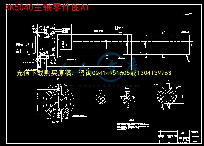
XK5040主轴零件图A1.dwg
XK5040立式铣床主轴箱装配图A0.dwg
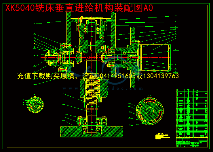
XK5040铣床垂直进给机构装配图A0.dwg
~WRL0122.tmp
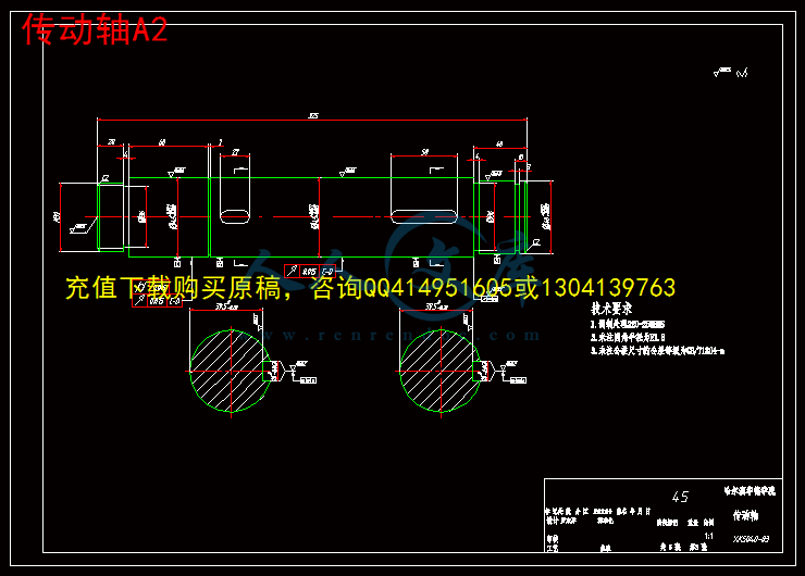
传动轴A2.dwg
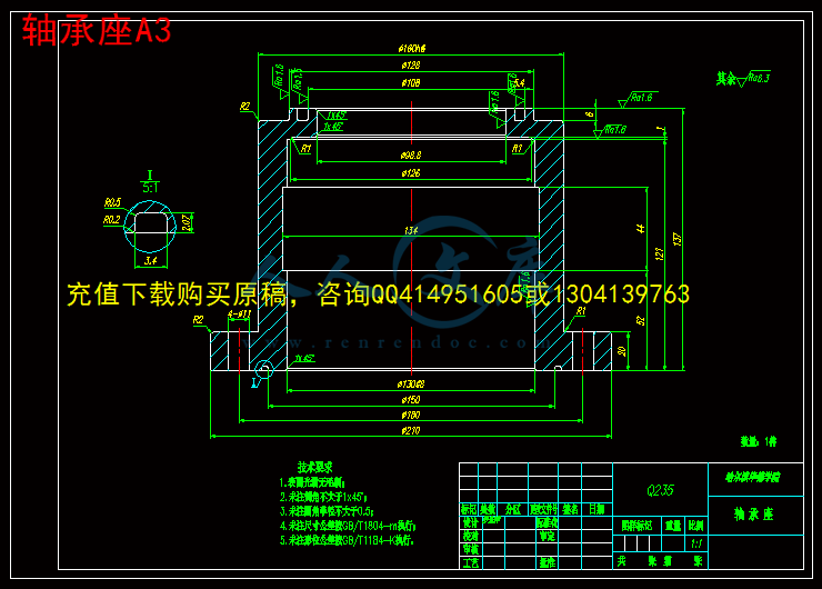
轴承座A3.dwg
压缩包内文档预览:(预览前20页/共82页)
预览图 预览图 预览图 预览图 预览图 预览图 预览图 预览图 预览图 预览图 预览图 预览图 预览图 预览图 预览图 预览图 预览图 预览图 预览图 预览图
编号:449828    类型:共享资源    大小:2.81MB    格式:RAR    上传时间:2015-07-06 上传人:好资料QQ****51605 IP属地:江苏
45
积分
关 键 词:
xk5040 数控 立式 铣床 结构设计 全套 cad 图纸 毕业 答辩 论文
资源描述:

摘  要

数控机床即数字程序控制机床,是一种自动化机床,数控技术是数控机床研究的核心,是制造业实现自动化、网络化、柔性化、集成化的基础。随着制造技术的发展,现代数控机床借助现代设计技术、工序集约化和新的功能部件使机床的加工范围、动态性能、加工精度和可靠性有了极大的提高。

本文主要对XK5040数控立式铣床及控制系统进行设计,首先分析立式铣床的加工特点和加工要求确定其主参数,包括运动和动力参数;根据主参数和设计要求进行主运动系统、进给系统设计。主要进行主运动系统和进给系统的机械结构设计及滚珠丝杠和步进电机的选型和校核。


关键词  数控技术;立式铣床;结构设计


Abstract


The numerical control engine bed is the digital process control engine bed, is one kind of automated engine bed, the numerical control technology is the core which the numerical control engine bed studies, is the manufacturing industry realization  automation, the network, the flexibility, the integrated foundation. Along with the manufacture technology development, the modern numerical control engine bed with the aid of the modern design technology, the working procedure intensification and the new function part caused the engine bed the processing scope, the dynamic  performance, the processing precision and the reliability had the enormous  enhancement .

This article mainly carries on the design to the XK5040 numerical control vertical milling machine , first analyzes the vertical milling machine the processing characteristic and the processing request determines its host parameter, including movement and dynamic parameter; Carry on the host kinematic scheme according to the host parameter and the design request, enters for the system and the control system hardware circuit design. Mainly carries on the host kinematic scheme and enters for the system mechanism design and the ball bearing guide screw and electric stepping motor shaping and the examination;

Key words  Numerical control technology; Vertical milling machine; Design


目  录

摘  要I

AbstractII

第1章  总体设计1

1.1铣床简介1

1.2 XK5040型数控铣床的总体布局主要技术参数及总传动系统图1

1.2.1  XK5040型数控铣床的总体布局1

1.2.2  XK5040型数控铣床的主要技术参数3

1.2.3  总传动系统图4

第2章 主运动系统设计 6

2.1 传动系统设计6

2.1.1参数的拟定6

2.1.2 传动结构或结构网的选择6

2.1.3 转速图拟定7

2.1.4齿轮齿数的确定及传动系统图的绘制10

2.2传动件的估算与验算14

2.2.1传动轴的估算和验算14

2.2.2齿轮模数的估算17

2.3 展开图设计 22

2.3.1结构实际的内容及技术要求22

2.3.2齿轮块的设计24

2.3.3传动轴设计26

2.3.4主轴组件设计29

2.4制动器设计35

2.4.1按扭矩选择35

2.5截面图设计37

2.5.1轴的空间布置37

2.5.2操纵机构38

2.5.3润滑38

2.5.4箱体设计的确有关问题39

第3章 进给系统设计40

3.1总体方案设计40

3.1.1对进给伺服系统的基本要求40

3.1.2进给伺服系统的设计要求40

3.1.3总体方案40

3.2进给伺服系统机械部分设计41

3.2.1确定脉冲当量计算切削力41

3.2.2滚珠丝杆螺母副的计算和造型43

3.2.3齿轮传动比计算53

3.2.4步进电机的计算和选型54

3.2.5进给伺服系统机械部分结构设计65

结论69

致谢70

参考文献71

附录172

附录274


第1章  总体设计

1.1铣床简介

铣床是一种用途广泛的机床。它可以加工平面(水平面、垂直面等)、沟槽(键槽、T型槽、燕尾槽等)、多齿零件上齿槽(齿轮、链轮、棘轮、花键轴等)、螺旋形表面(螺纹和螺旋槽)及各种曲面。此外,它还可以用于加工回转体表面及内孔,以及进行切断工作等。

由于铣床使用旋转的多齿刀具加工工件,同时有数个刀齿参加切削,所以生产效率高,但是,由于铣刀每个刀齿的切削过程是断续的,且每一个的切削厚度又是变化的,这就使切削力相应地发生变化,容易引起机床振动,因此,铣床在结构上要求有较高的刚度和抗振性。

铣床的类型很多,主要类型有:卧式升降台铣床、立式升降台铣床、龙门铣床、工具铣床和各种专门化铣床等。

随着科学技术的进步,数控铣床得到了越来越广泛的应用,它一般分为立式和卧式两种,一般数控铣床是指规格较小的升降台数控铣床,其工作台宽度多在400mm以下,规格较大的数控铣床,例如工作台宽度在500mm以上的,其功能已向加工中心靠近,进而演变成柔性制造单元。数控铣床多为三坐标、两轴联动的机床,也称两轴半控制,即X、Y、Z三个坐标轴中,任意两个都可以联动。一般情况下,在数控铣床上只能用来加工平面曲线的轮廓。对于有特殊要求的数控铣床,还可以加进一个回转的A坐标或C坐标,即增加一个数控分度头或数控回转工作台,这是机床的数控系统为四坐``标的数控系统,它可用来加工旋转槽、叶片等立体曲面零件。

我们本次设计过程中要接触到的为XK5040数控立式铣床。它的工作台宽度为400mm。


内容简介:
学生 实习报告 院(系): 机械工程学院 专业 : 机械设计制造及其自动化 班级: 姓名: 一、 实习的主要内容 2007 年 1 月份开始 ,我在广东的一个日资企业技术部实习 ,主要从事注塑机周边设备的设计 ,主要有除湿干燥机 ,模温机 ,粉碎机等系列产品 ,我们实习的主要内容是: 1、参加由公司组织的理论知识的学习,由有经验的领导、工程师授课,学习公司的文化、以及公司的发展前景、主要产品的生产流程和必要的技术要求以及一些改进方向、公司必须保留和更新发展的技术核心等等。 2、 在公司 ,实习期间我主要完成了新款除湿机 NS-25 系 列的机箱钣金件的二维图绘制和三维绘制 ,将零件装配起来 ,完成一个实体图 ,以便校核和模拟 ,同时绘制了 NS-100 系列的二维图 ,并在设计过程中制作机器明细表等,所需零件全部准备好之后 ,再行组装。在组装过程中进一步了解到哪个零件是否合理 ,如果不合理怎么样加以改进 ,使以后批量生产中不会出现同样的错误。 3、 熟悉了除湿干燥机的工作原理 ,并对新开发的除湿机做彩页说明 ,包括中英文对照 ,参数等的设定,为销售作好前期工作。 4、 对新机器制作网页,因为网络是一个最快速且先进的交流工具,使客户能够第一时间了解我们公司的产品及开发进程。 5、对机器上的每一个零件摄影,并且用 PhotoShop 对图片进行处理,完成了公司里面全部零件的处理工作。并且熟悉了 PhotoShop 软件的应用。 nts二、实习取得的经验及收获: 通过一段时间在公司的实习,使我受益匪浅。 1、首先让自己对社会有了一定的了解,对公司的文化、产品有了一定的认识,为自己在以后的人生路上做了一个很好的铺垫,并逐步养成了吃苦耐劳的精神,培养了团结一致的团队精神。 2、了解了一般公司要想发展所应具备的基本要求,必须具备创新能力开发出新型的能够符合市场竞争需要的新产品,才能够在市场竞争中立于不败之地。 3、通过这一段时间的实习, 使我对学校里学的理论知识有了更深入的了解,并且能够熟练应用 CAD, PROE , PhotoShop 等软件,对办公软件也更加熟练。 4、经过了这段实习生活后,加深巩固了以前学校里学的知识,同时也了解到了以前学校里面学不到的东西,极大的拓宽了我的视野及知识面,为今后的正式工作生活奠定了一个良好的基础。 三、 存在的不足及建议 通过实习我本人感觉到 还有很多不足的地方: a) 我们学习了四年的理论知识,初步了解了机械行业的基础知识,但在实际生产中这些还是不够的,“书到用时方恨少”真实的说明了这个道理。 b) 初到公司缺乏工作经验,很多的工作感到无从下手,没有一个完整的头绪,很难单独去接受一个实际的课题。 通过实习我想对学校一点建议: 1 学校是否考虑注重学生的实际动手能力,加强学生的实践能力的培养,如增加学生的在校实习的机会和延长学生的实践活动的时间、更加注重在老师的指导下让学生真正的参与到实践中去。 2 毕业设计期间学校是否能考虑组织学生到生产现场去参观实习,让学生接 受最为直接的设计基本知识,比凭空去设想更有效果。 nts 哈尔滨工业大学华德应用技术学院 毕业设计(论文) 题 目 XK5040 数控立式铣床结构设计 专 业 机械制造及其自动化 学 号 1109511131 学 生 罗东洋 指 导 教 师 赵跃超 答 辩 日 期 2013.12.17 哈工大华德学院 nts 哈工大华德学院毕业设计 (论文)评语 姓名: 罗东洋 学号: 109511131 专业: 数 控 技 术 毕业设计(论文)题目 : XK5040 数控立式铣床结构设计 工作起止日期: 2013 年 9 月 20 日起 2013 年 12 月 17 日止 指导教师对毕业设计(论文)进行情况,完成质量及评分意见: _ 指导教师签字: 指导教师职称: 评阅人评阅意见: _ _ _ _ 评阅教师签字: _ 评阅教师职称: _ nts 答辩委员会评语: _ 根据毕业设计(论文)的材料和学生的答辩情况,答辩委员会作出如下评定: 学生 毕业设 计(论文)答辩成绩评定为: 对毕业设计(论文)的特殊评语: _ 答辩委员会主任(签字): 职称: _ 答辩委员会副主任(签字): 答辩委员会委员(签字): _ _ _ _ _ _ _ _ _ _ _ _ _ _ _ 年 月 日 nts 哈工大华德学院毕业设计(论文)任务书 姓 名 : 罗东洋 院 (系):汽车与机电工程 学院 专 业:机 械 制 造 及 其 自 动 化 班 号: 1095111 任务起至日期: 2013 年 9 月 20 日至 2013 年 12 月 17 日 毕业设计(论文)题目: XK5040 数控立式铣床 结构设计 立题的目的和意义: 数控机床是一种加工效率高、集成度高、用途广泛的机床,现已广泛应用于各个领域,对数控机床研究成为现代机床设计重要课题。铣床主要是利用刀具的旋转将工件表面多余的部分一层一层的切削而除去,从而形成具有一定尺寸,形状和精度的工件。在一般的生产体系中,铣床的加工范围占整个机器生产的重要部分,所以对数控铣床的结构设计具有很重要的意义。 技术要求与主要内容: 分析 XK5040 数控立式铣床的加工特点,确定 新设计数控立式铣床的主要技术参数; 进行数控立式铣床的总体方案设计; 进行主运动和进给的机械结构设计。 进度安排: 1. 9 月 10 日 毕业设计动员导师与学生见面,下达设计任务书 J103 2. 9 月 20 日 开题 T207, T205, T204, T201, Q209 3. 11 月 5 日 中期检查 T204.T201.T206 4. 12 月 5 日 结题验收 T204.T201.T206 5. 12 月 15 日 上交论文 Q209 6. 12 月 17 日 12 月 18 日 导师交叉批阅论文 T204 7. 12 月 19、 20 日 答辩委员会分组答辩 Q209, T207, T205.T204.T201各组同时进行 nts 同组设计者及分工: 独立完成 指导教师签字 _ 年 月 日 系(教研室)主任意见: 系(教研室)主任签字 _ 年 月 日 ntsJournal of Materials Processing Technology xxx (2005) xxxxxxAbstractoperations.metal-cuttingforfeed-rateconductedK1.theofaremeragearederEvanthemachiningnecessarysatisfytioperatingAtainconditions.de0924-0136/$doi:10.1016/j.jmatprotec.2005.02.143Fuzzy control strategy for an adaptive force control in end-millingU. Zuperl, F. Cus, M. MilfelnerFaculty of Mechanical Engineering, University of Maribor, Smetanova 17, 2000 Maribor, SloveniaThis paper discusses the application of fuzzy adaptive control strategy to the problem of cutting force control in high speed end-millingThe research is concerned with integrating adaptive control with a standard computer numerical controller (CNC) for optimising aprocess. It is designed to adaptively maximise the feed-rate subject to allowable cutting force on the tool, which is very beneficiala time consuming complex shape machining. The purpose is to present a reliable, robust neural controller aimed at adaptively adjustingto prevent excessive tool wear, tool breakage and maintain a high chip removal rate. Numerous simulations and experiments areto confirm the efficiency of this architecture.2005 Elsevier B.V. All rights reserved.eywords: End-milling; Adaptive force control; FuzzyIntroductionA remaining drawback of modern CNC systems is thatmachining parameters, such as feed-rate, speed and depthcut, are programmed off-line. The machining parameterssimulations with the fuzzy control strategy are carried out.The results demonstrate the ability of the proposed system toeffectively regulate peak forces for cutting conditions com-monly encountered in end-milling operations.Force control algorithms have been developed and eval-usually selected before machining according to program-s experience and machining handbooks. To prevent dam-and to avoid machining failure the operating conditionsusually set extremely conservative.As a result, many CNC systems are inefficient and run un-the operating conditions that are far from optimal criteria.en if the machining parameters are optimised off-line byoptimisation algorithm 5 they cannot be adjusted duringmachining process.To ensure the quality of machining products, to reduce thecosts and increase the machining efficiency, it isto adjust the machining parameters in real-time, tothe optimal machining criteria. For this reason, adap-ve control (AC), which provides on-line adjustment of theconditions, is being studied with interest 3.InourC system, the feed-rate is adjusted on-line in order to main-a constant cutting force in spite of variations in cuttingIn this paper, a simple fuzzy control strategy isveloped in the intelligent system and some experimentalCorresponding author. Tel.: +386 2 220 7623; fax: +386 2 220 7990.E-mail address: uros.zuperluni-mb.si (U. Zuperl).uatedisnallyantrollerditions.trollerandatedallthetems,bysentedtesystems3controlhasmotion.for see front matter 2005 Elsevier B.V. All rights reserved.by numerous researchers. Among the most commonthe fixed gain proportional integral (PI) controller origi-proposed for milling by 4. Kim et al. 4 proposedadjustable gain PI controller where the gain of the con-is adjusted in response to variations in cutting con-The purely adaptive model reference adaptive con-(MRAC) approach was originally investigated by CusBalic 2. These controllers were simulated and evalu-and physically implemented by 1. Both studies foundthree-parameter adaptive controller to perform better thanfixed gain PI controller. As regards fuzzy control sys-an introductory survey of pioneering activities is givenHuang and Lin 3, and a more systematic view is pre-by in 4. Comparisons of fuzzy with proportional in-gral derivative (PID) control and stability analysis of fuzzyand supervisory fuzzy control are addressed in Ref.Much work has been done on the adaptive cutting forcefor milling 2. However, most of the previous worksimplified the problem of milling into one-dimensionalIn this contribution, we will consider force controlthree-dimensional milling.nts2 Processingscribesthesimulation/eposedimentalresearch.2.fuzzyseteThewhichplementcontrolmoreTherateasthecomparedcontrolFuzzyratecuttingcreasesrates,productionarebreakage.callytheforbelo.signingonactualcentagemisationalcorrectcontrolleraplepro2.1.aaboutinputoperatorthroughU. Zuperl et al. / Journal of MaterialsThe paper is organised as follows. Section 2 briefly de-the overall force control strategy. Section 3 coversCNC machining process model. Section 5 describes thexperiments and implementation method of pro-control scheme. Finally, Sections 6 and 7 present exper-results, conclusions, and recommendations for futureAdaptivefuzzycontrollerstructureA new on-line control scheme which is called adaptivecontrol (AFC) (Fig. 1) is developed by using the fuzzytheory. The basic idea of this approach is to incorporate thexperience of a human operator in design of the controller.control strategies are formulated as a number of rulesare simple to carry out manually but difficult to im-by using conventional algorithm. Based on this newstrategy, very complicated process can be controlledeasily and accurately compared to standard approaches.objective of fuzzy control is keeping the metal removal(MRR) as high as possible and maintaining cutting forceclose as possible to a given reference value. Furthermore,amount of computation task and time can be reduced asto classical or modern control theory. Schematicrules are constructed by using real experimental data.adaptive control ensures continuous optimising feedcontrol that is automatically adjusted to each particularsituation. When spindle loads are low, the system in-cutting feeds above and beyond pre-programmed feedresulting in considerable reductions in cycle times andcosts. When spindle loads are high the feed rateslowered, safeguarding machine tools from damage fromWhen system detects extreme forces, it automati-stops the machine to protect the cutting tool. It reducesneed for constant operator supervision. Sequence of stepson-line optimisation of the milling process are presentedw.namicstheasvofcuttinglated,Delta1forceFig. 1. Comparison of actualTechnology xxx (2005) xxxxxxThe pre-programmed feed rates are sent to CNC controllerof the milling machine.The measured cutting forces are sent to the fuzzy con-troller.Fuzzy controller uses the entered rules to find (adjust) theoptimal feed-rates and sends it back to the machine.Steps 1 and 3 are repeated until termination of machining.The adaptive force controller adjusts the feed-rate by as-a feed-rate override percentage to the CNC controllera four-axis Heller, based on a measured peak force. Thefeed-rate is the product of the feed-rate override per-and the programmed feed-rate. If the feed-rate opti-models were perfect, the optimised feed-rate wouldways be equal to the reference peak force. In this case theoverride percentage would be 100%. In order for theto regulate peak force, force information must bevailable to the control algorithm at every controller sam-time. A data acquisition software (Labview) is used tovide this information.Structure of a fuzzy controllerIn fuzzy process control, expertise is encapsulated intosystem in terms of linguistic descriptions of knowledgehuman operating criteria, and knowledge about theoutput relationships. The algorithm is based on thes knowledge, but it also includes control theory,the error derivative, taking into consideration the dy-of the process. Thus, the controller has as its inputs,cutting force error Delta1F and its first difference Delta12F, andoutputs, the variation in feed rate Delta1f. The fuzzy controlariables fuzzification (see Fig. 2) as well as the creationthe rules base were taken from the expert operator. Theforce error and first difference of the error are calcu-at each sampling instant k, as: Delta1F(k)=FrefF(k) and2F(k)=Delta1F(k)Delta1F(k1), where F is measured cuttingand Frefis force set point.and model feed-rate.nts3.etalandforcesscribedmachinefeedingfitquencefromformcommandedtingmodel.mentalfeed-rateU. Zuperl et al. / Journal of Materials ProcessingFig. 2. Structure of a fuzzyCNCmachiningprocessmodelA CNC machining process model simulator is used tovaluate the controller design before conducting experimen-tests. The process model consists of a neural force modelfeed drive model. The neural model estimates cuttingbased on cutting conditions and cut geometry as de-by Zuperl 1. The feed drive model simulates theresponse to changes in commanded feed-rate. Thedrive model was determined experimentally by examin-step changes in the commanded velocity. The best modelwas found to be a second-order system with a natural fre-y of 3 Hz and a settling time of 0.4 s. Comparison ofxperimental and simulation results of a velocity step change7 to 22 mm/s is shown on Fig. 3.The feed drive and neural force model are combined tothe CNC machining process model. Model input is thefeed-rate and the output is the X, Y resultant cut-force. The cut geometry is defined in the neural forceThe simulator is verified by comparison of experi-and model simulation results. A variety of cuts withchanges were made for validation.changeFig.resultsTechnology xxx (2005) xxxxxx 3controller.The experimental and simulation resultant force for a stepin feed-rate from 0.05 to 2 mm/tooth is presented in4. The experimental results correlate well with modelin terms of average and peak force. The experimentalFig. 3. Comparison of actual and model federate.nts4resultsandthe3.1.dardlarimentsforceusedfederatedialforcesaryU. Zuperl et al. / Journal of Materials ProcessingFig. 4. Structure of a fuzzycorrelate well with model results in terms of averagepeak force.The obvious discrepancy may be due to inaccuracies inneural model, and unmodeled system dynamics.Cutting force modelingTo realise the on-line modelling of cutting forces, a stan-BP neural network (NN) is proposed based on the popu-back propagation leering rule. During preliminary exper-it proved to be sufficiently capable of extracting themodel directly from experimental machining data. It isto simulate the cutting process.The NN for modelling needs four input neurons for milling(f), cutting speed (vc) axial depth of cut (AD) and ra-depth of cut (RD). The output from the NN are cuttingcomponents, therefore two output neurons are neces-. The detailed topology of the used NN with optimal train-ingalso73.2.modelingferentberefnetwysed.difandtheinputconclusionsTechnology xxx (2005) xxxxxxcontroller.parameters and mathematical principle of the neuron isshown in Fig. 5. Best NN configuration contains 5, 3 andhidden neurons in hidden layers.Topology of neural network and its adaptation toproblemThe effect of topology is also studied by considering dif-cases. The topologies are varied by varying the num-of neurons in hidden layers. To evaluate the individualfects of training parameters on the performance of neuralork 40 different networks were trained, tested and anal-The network performances were evaluated using fourferent criteria 5: ETstMax, ETst, ETrn, and ETrnMaxthe number of training cycles. The number of neurons ininput and output layers are determined by the number ofand output parameters. From the results the followingcan be drawn.ntsProcessing4.equipmentsystemandwere9255)table.beelectricelectrictransmittedthemulti-channelamplifierquiredofpendingterfU. Zuperl et al. / Journal of MaterialsFig. 5. Structure of a fuzzyLearning rates below 0.3 give acceptable prediction errorswhile learning rates must be between 0.01 and 0.2 to min-imise the number of training cycles.To minimise the estimation errors, momentum rates be-tween 0.001 and 0.005 are good. However, the momentumrate should not exceed 0.004 if the number of training cy-cles is also to be minimised.The optimum number of hidden layer nodes is 3 or 6. Net-works with between 2 and 12 hidden layer nodes, otherthan 3 or 6, also performed fairly well but resulted in highertraining cycles.Networks that employ the sine function require the lowestnumber of training cycles followed by the ArcTangent,while those that employ the hyperbolic tangent require thehighest number of training cycles.DataacquisitionsystemandexperimentalThe data acquisition equipment used in this acquisitionconsists of dynamometer, fixture module, hardwaresoftware module as shown in Fig. 1. The cutting forcesmeasured with a piezoelectric dynamometer (Kistlermounted between the workpiece and the machiningWhen the tool is cutting the workpiece, the force willapplied to the dynamometer through the tool. The piezo-quartz in the dynamometer will be strained and ancharge will be generated. The electric charge is thento the multi-channel charge amplifier throughconnecting cable. The charge is then amplified using thecharge amplifier. In the multi-channel charge, different parameters can be adjusted so that the re-resolution can be achieved. Essentially, at the outputthe amplifier, the voltage will correspond to the force de-on the parameters set in the charge amplifier. The in-ace hardware module consists of a connecting plan block,analogueinterfloguetheThedirectionstheneouslyforceabletinglectedwithterialincoolanttrolandcationchinefeed-rateableof5.fuzzyulationthemilling45(cuttingselectedTechnology xxx (2005) xxxxxx 5controller.signal conditioning modules and a 16 channel A/Dace board (PC-MIO-16E-4). In the A/D board, the ana-signal will be transformed into a digital signal so thatLabVIEW software is able to read and receive the data.voltages will then be converted into forces in X, Y and Zusing the LabVIEW program. With this program,three axis force components can be obtained simulta-, and can be displayed on the screen for analysingchanges. The ball-end-milling cutter with interchange-cutting inserts of type R216-16B20-040 with two cut-edges, of 16 mm diameter and 10helix angle was se-for machining. The cutting inserts R216-1603 M-M12rake angle were selected. The cutting insert ma-is P30-50 coated with TiC/TiN, designated GC 4040P10-P20 coated with TiC/TiN, designated GC 1025. TheRENUS FFM was used for cooling. The fuzzy con-is operated by the intelligent controller module (Labview)the modified feed-rates are send to the CNC. Communi-between the force control software and the NC ma-controller is enabled through memory sharing. Theoverride percentage variable DNCFRO is avail-to the force control software for assignment at a rate1 kHz.SimulationsandfuzzycontrolmillingexperimentTo examine the stability and robustness of the adaptivecontrol strategy, the system is first examined by sim-using Simulink and Labview fuzzy Toolset. Thensystem is verified by various experiments on a CNCmachine (type HELLER BEA1) for Ck 45 and Ck(XM) steel workpiece with variation of cutting depthFig. 6).The ball-end-milling cutter (R216-16B20-040) with twoedges, of 16 mm diameter and 10helix angle wasfor experiments. Cutting conditions are: millingnts6 U. Zuperl et al. / Journal of Materials Processing Technology xxx (2005) xxxxxxwidthveTo use the fuzzy control structure on Fig. 1 and to opti-mise the feed-rate, the desired cutting force is Fref = 280 N,pre-programmed feed is 0.08 mm/teeth and its allowable ad-justing rate is 0150%.Fig. 7 is the response of the cutting force and the feed-ratewhen the cutting depth is changed. It shows the experimentalresultcuttingisFig.adaptiFig. 6. Workpiece profile.RD= 3 mm, milling depth AD= 2 mm and cutting speedc= 80 m/min.The parameters for fuzzy control are the same as for thexperiments for the traditional system performance.twaxial2enceoftionsrunditions.axial2000depthmainsperformance.7. Experimental results with variable cutting depth. Response of MRR, resultingve fuzzy control.where the feed-rate is adjusted on-line to maintain theforce at the maximum desired value.Simulated control response to a step change in axial depthpresented in Fig. 8. The simulation represents a 16 mm,o-flute cutter, at 2000 rpm, encountering a step change indepth from 3 to 4.2 mm. The step change occurs ats and the controller returns the peak forces to the refer-peak force within 0.5 s. In this research the stabilityfuzzy controller is evaluated by simulation. Test simula-with small and large step changes in process gain areto ensure system stability over a range of cutting con-Small process gain changes are simulated with andepth change from 3 to 4.2 mm at a spindle speed ofrpm. Large gain changes are simulated with an axialchange from 3 to 6 mm at 2000 rpm. The system re-stable in all simulation tests, with little degradation incutting force, feed-rate. (a) Conventional milling and (b) milling withntsProcessing6.tionalinpiecemuchcontrolfeed-ratetraditionalpointisefproingsystemadjustment;tryandThetheitytrollers.tantvU. Zuperl et al. / Journal of MaterialsFig. 8. Simulated fuzzy control response to a step change in axial depth.ResultsanddiscussionIn the first experiment using constant feed rates (conven-cutting, Fig. 7a) the MRR reaches its proper value onlythe last step.However, in second test (Fig. 7b), machining the samebut using fuzzy control, the average MRR achieved ismore close to the proper MRR.Comparing Fig. 7a and b, the cutting force for the neuralmilling system is maintained at about 240 N, and theof the adaptive milling system is close to that of theCNC milling system from point C to point D. FromA to point C the feed-rate of the adaptive milling systemhigher than for the classical CNC system, so the millingficiency of the adaptive milling system is improved.The experimental results show that the MRR can be im-ved by up to 27%. As compared to most of the exist-end-milling control systems, the proposed fuzzy control
温馨提示:
1: 本站所有资源如无特殊说明,都需要本地电脑安装OFFICE2007和PDF阅读器。图纸软件为CAD,CAXA,PROE,UG,SolidWorks等.压缩文件请下载最新的WinRAR软件解压。
2: 本站的文档不包含任何第三方提供的附件图纸等,如果需要附件,请联系上传者。文件的所有权益归上传用户所有。
3.本站RAR压缩包中若带图纸,网页内容里面会有图纸预览,若没有图纸预览就没有图纸。
4. 未经权益所有人同意不得将文件中的内容挪作商业或盈利用途。
5. 人人文库网仅提供信息存储空间,仅对用户上传内容的表现方式做保护处理,对用户上传分享的文档内容本身不做任何修改或编辑,并不能对任何下载内容负责。
6. 下载文件中如有侵权或不适当内容,请与我们联系,我们立即纠正。
7. 本站不保证下载资源的准确性、安全性和完整性, 同时也不承担用户因使用这些下载资源对自己和他人造成任何形式的伤害或损失。
提示  人人文库网所有资源均是用户自行上传分享,仅供网友学习交流,未经上传用户书面授权,请勿作他用。
关于本文
本文标题:XK5040数控立式铣床结构设计【5张CAD图纸+毕业答辩论文】
链接地址:https://www.renrendoc.com/p-449828.html

官方联系方式

2:不支持迅雷下载,请使用浏览器下载   
3:不支持QQ浏览器下载,请用其他浏览器   
4:下载后的文档和图纸-无水印   
5:文档经过压缩,下载后原文更清晰   
关于我们 - 网站声明 - 网站地图 - 资源地图 - 友情链接 - 网站客服 - 联系我们

网站客服QQ:2881952447     

copyright@ 2020-2025  renrendoc.com 人人文库版权所有   联系电话:400-852-1180

备案号:蜀ICP备2022000484号-2       经营许可证: 川B2-20220663       公网安备川公网安备: 51019002004831号

本站为文档C2C交易模式,即用户上传的文档直接被用户下载,本站只是中间服务平台,本站所有文档下载所得的收益归上传人(含作者)所有。人人文库网仅提供信息存储空间,仅对用户上传内容的表现方式做保护处理,对上载内容本身不做任何修改或编辑。若文档所含内容侵犯了您的版权或隐私,请立即通知人人文库网,我们立即给予删除!