设计评价分析.doc

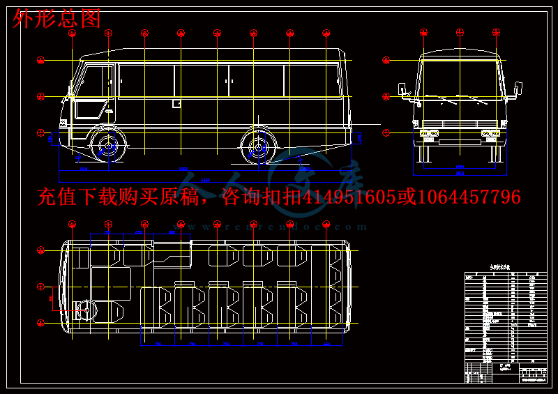
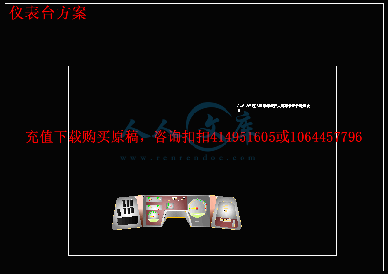
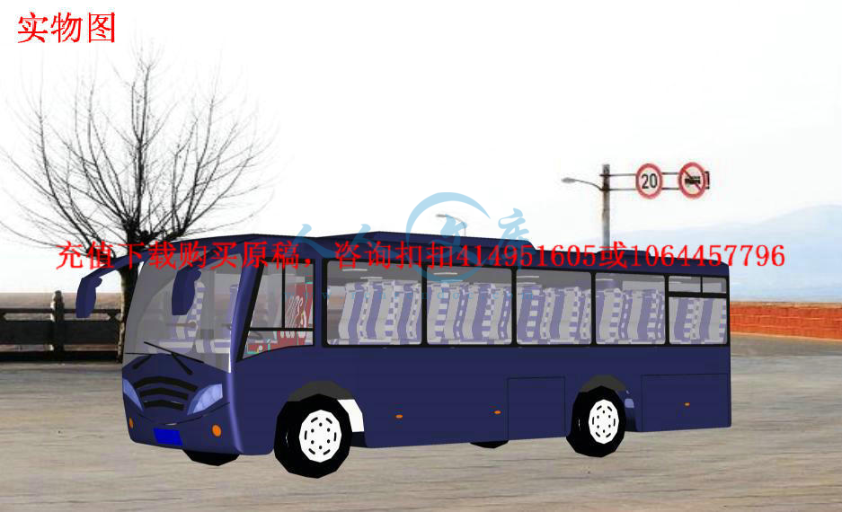
兼容残疾轮椅的中型客车造型设计【2张CAD图纸+WORD毕业论文】【车辆专业】

收藏

压缩包内文档预览:
预览图
编号:471453    类型:共享资源    大小:1.95MB    格式:RAR    上传时间:2015-08-12 上传人:好资料QQ****51605 IP属地:江苏
45
积分
关 键 词:
兼容 残疾 轮椅 中型 客车 造型 设计 全套 cad 图纸 word 毕业论文 车辆 专业
资源描述:

目录


第一章  绪论………………………………………………………………………………1

1.1造型设计的重要性……………………………………………………………1

1.2国外客车造型的现状与发展趋势………………………………………………2

1.2.1具有东方风格的日本式…………………………………………………3

1.2.2 欧式豪华大客车的几种典型风格………………………………………3

1.2.3美洲大客车………………………………………………………………4

1.3国内客车造型设计的现状及发展趋势…………………………………………4

1.3.1长途,旅游客车………………………………………………………4

1.3.2城市客车  ………………………………………………………………5

1.3.3高档豪华客车……………………………………………………………6

第二章  造型设计的特点,基本原则及要求……………………………………………7

2.1造型设计的特点…………………………………………………………………7

2.2造型设计的原则…………………………………………………………………7

2.3造型设计的要求和方法………………………………………………………9

2.3.1外型……………………………………………………………………9

2.3.2车内布局………………………………………………………………9

第三章  客车造型的特点以及形式的确定……………………………………………11

3.1客车造型的特点………………………………………………………………11

3.1.1中型客车,适用于城市之间的中短途运输…………………………11

3.1.2发动机前置……………………………………………………………11

3.1.3前悬短,乘客门中置…………………………………………………11

3.1.4兼容残疾人座椅………………………………………………………11

3.2整车造型设计方案以及CAD三维实体模型的建立…………………………12

3.2.1造型设计的重点部分……………………………………………………12

3.2.2本车造型特点……………………………………………………………14

3.2.3 造型的表达以及CAD模型的建立………………………………15

第四章  内饰,保险杠及附件的设计……………………………………………………20

4.1内饰……………………………………………………………………………20

4.2保险杠…………………………………………………………………………20

4.2.1单一式保险杠……………………………………………………20

4.2.2 整体组合式保险杠……………………………………………20

4.2.3复合式保险杠………………………………………………21

4.3附件……………………………………………………………………………21

4.4安全装置………………………………………………………………………22

第五章  材料选用与工艺特点…………………………………………………………23

5.1材料选用………………………………………………………………………23

5.2工艺特点………………………………………………………………………23

第六章  存在的不足及改进的途径……………………………………………………24

6.1本车的造型设计存在的不足…………………………………………………24

6.2改进的途径……………………………………………………………………24

设计评价分析……………………………………………………………………………25

致谢………………………………………………………………………………………26

参考文献…………………………………………………………………………………27


摘 要


汽车造型相当重要,它不但直接影响整车的视觉效果,同时也在很大程度上影响到产品的市场表现。研究不同档次客车的造型风格和时代流行趋势,寻找其内在关系,对于企业新产品开发具有重要的指导意义。

文章简要介绍我国客车造型的发展和现状,较详细的说明了客车整体、局部造型及内饰技术和在造型中应注意的一些问题。介绍了客车造型设计的含义和评价标准。简述了构思草图、效果图、模型在客车造型设计过程中的作用。

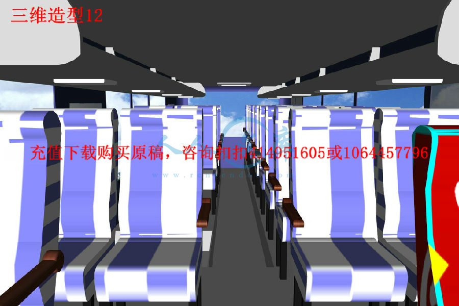
在本车的造型设计过程中,结合兼容残疾人座椅的造型特点,在客车外观,内饰设计和一些细节问题上都有所创新,并通过CAD软件在三维设计过程中表现出来。通过对客车造型特点的研究,把握市场对客车造型的需求,提高产品的市场竞争力。


关键词:客车,造型,设计,CAD,残疾人


ABSTRACT

Automobile styling is important, it will not only directly affect the vehicle's visual effects, they have also greatly affected the product's market performance. Study of different grades and 380 modeling style and the era fashion trends, finding its intrinsic relationship For enterprise new product development is of great significance.

The article briefly introduced China Bus modeling development and the status quo, a more detailed explanation of the whole bus, Interior and Local modeling and modeling technology should pay attention to the issue. Passenger train on the meaning of Design and evaluation criteria. Plan outlines the concept, the effect map, model passenger cars in the design process modeling role.

In the shape of the car design process, compatible with the disabled seating modeling features, the Bus appearance, Interior design and some of the details on both innovation and the adoption of 3D CAD software in the design process demonstrated. By modeling features of the bus, the bus market grasp the shape of demand, improve product competitiveness on the market.


Key word: automobile, styling, design, CAD, disabled


绪论  国内外客车造型的现状及发展趋势分析


1.1造型设计的重要性

爱美之心,人皆有之。美的事物总会给人以视觉上的冲击,让人难忘。(见图1-1)


图1-1  宇通客车

造型是为了满足人们的特定需要、并受其制约而创造设计并加工出来的特定形式,主要包括形态、质地与色彩、人机关系等内涵。造型款式不仅本身是评价汽车产品好坏的重要指标之一,还和汽车性能、质量、价格等方面的指标有密切的相关性,因此车身的造型设计在汽车产品设计中占有十分突出的地位。

汽车造型设计是汽车设计过程中的一个重要的组成部分。汽车造型设计是指汽车总布置和车身总布置基本确立之后进一步使汽车获得具体形状和艺术面貌的过程,它包括外型设计和室内造型设计。汽车造型设计师的工作是:参与汽车总布置设计和车身总布置设计,绘制效果图,塑制模型,将外形形体上的曲线表达在主图版上,制定室内造型和覆饰,最后协同结构设计师将造型形象的体现在具体的车身结构上。

在汽车造型设计中要考虑多方面的要求,包括空气动力学、机械工程学、人机工程学、安全法规、美学等要素。其中机械工程学和人机工程学要素已达到相当成熟的发展阶段,对车身内、外造型的要求与约束形成了较为固定的规范。从这个意义上讲,现代汽车车身造型(尤其是外部造型)的演变与发展,很大程度上受汽车空气动力学和造型美学两大变数的影响甚至支配。

汽车造型设计不是那种附属的简单的美化工作,而是独特的综合创作。因为汽车不仅是现代化的工业产品和交通工具,而且是一件精致的艺术品,是科学技术与艺术技巧的高度融会交织的结晶。汽车的造型既包含结构、性能、工艺等科学技术因素的作用和影响。为了承担这项工作,汽车造型设计师应具备广泛的知识和较高的艺术素质。

在国外,各厂商还把汽车造型设计视为占领市场、打开销路的竞争手段,对造型工作倍加重视。为了与瞬息万变的市场相适应,各厂商都制定较多的车型方案,以便从中选择适合市场销售形势的方案投产,因而需要大量的技术储备和庞大的技术班子。由于对造型人才的要求较高,需要精心培养和训练,他们有时甚至不惜重金聘请外国名师带行造型设计。
内容简介:
机动车轮椅固定及其使用者的约束系统 前言 为了那些使用机动车旅行却没有能力从轮椅中移动出来的人,轮椅必须像汽车座椅一样来使用。这就通常意味着由车辆制造商提供的成员约束系统在某些紧急状况下不能够提供足够的保护。另外,轮椅必须被固定在车上以便不会强加载荷给它的使用者,并且在 碰撞或突然的车 辆 回旋 情况下不会对其他车上人员造成伤害。因此,要为轮椅及其使用者提供约束性的保护,使用一些零部件以及相关的设备来固定轮椅并对其使用者进行约束。 这篇设计和机动车性能表现方面的文章论述的就是轮椅的固定及其使用者的约束系统,简称 为 WTODS。它的目的就是为了鼓励设计,测试和实施。使用 WTODS系统在正面碰撞时可以有效的保证轮椅的安全和约束使用者,并且在某些特定情况下的表现是可以与制造商提供的乘坐安全性和轮椅使用者的约束相比较的。我们关心的主要是机动车在发生正面碰撞的情况下轮椅使用者所能受到的潜在伤害,也希望在成功保护轮椅使用者的同时,在正常的旅行期间可以增加驾驶员及其他成员的安全性和舒适性。这篇文章不应该被用来鼓励那些没有能力驾驶或者限制对轮椅进行运输的情况。 因为 WTODS 的制造商们不能控制和指定他们产品的最终用途,所以 48KM/H,20G 的冲击测试被指定在附录 A 中,用来限制 WTODS 系统在总重量小于 7000KG的整车上的使用。在更大的车辆中,也可以使用 WTODS 系统来保证运输的安全性,但是不会依照这篇文章所提到的使用标准。 和任何一个座椅相比,轮椅是成员安全系统的一个重要组成部分,并会在正常旅行期间为使用者提供稳定性和舒适性。轮椅的设计和表现在机动车的乘坐中是被单独谈论的,但相应的 ANSI/RESNA 标准正在发展中。 设计要求: 1 完成 WTORS-WTORS应 : a. 以一个轮椅和一个乘员为使用对象; b. 不要求用来固定轮椅和实施成员 约束的零件穿过轮椅的轮子; c. 在不使用工具的情况在在 60 秒内可以对轮椅及其使用者进行脱离; d. 不需要拆除轮椅的材料, 钻探轮椅架 , 变形轮椅 , 焊接 , 或者使用粘合剂 ,安装期间 , 除非是为 WTORS 系统使用的特殊轮椅或轮椅制造商允许的造型变革; e. 一旦安装,可不使用工具操作; f. 硬件设备 , 只包括永久连接的 WTORS或 WTORS组件 ; g. 设计要 防止无意中将所有螺纹紧固件松动 ; h. 包括一个人工代用装置,在电源故障的情况下解除固定和约束; ntsi. 包括锚地紧固件 , 硬件和 符合 规格 的类似 硬件 ,下面是 基于 材料, 大小 和紧固件 的 使用量模拟试验附录 A; 2轮椅的固定及固定的组件应: a. 不需要依靠轮椅进行制动; b. 轮椅的安全性能实现是依靠固定件的设计,而不是依靠成员约束来实现; c. 提供一个不使用工具来消除轮椅自由移动的方法; d. 如果 WTORS 系统采用了四点皮带固定方式,那么每条皮带都可以不使用工具来进行长度调节,这类的调整幅度,前带后带所能达到的最高值和最低值包含在表格 1中,包括一个至少有 25MM的皮带延长调整机构; 表格 1-四点皮带固定方式的扩展调整幅度: 皮带交汇点 最小长度( MM) 最大长度( MM) 后排 485( 19) 740( 29) 前排 410( 16) 710( 28) 长度定义为从轮椅安全点相对应的固定交点到沿着皮带的长度方向与轮椅接地平面线的交点的直线距离 e. 计算说明安全点与其他四个固定点在几何学上的关系,在附录 E4 中说明了在结构上安全点与其他组成部分的关系; f. 包含一个通过视觉或听觉来引起注意的设备,在相接处准确衔接后会予以显示; 3成员约束 -WTORS 也可以被设计成通过乘 客或驾驶员进行约束,包含的成员约束应满足以下要求: 3 1 WTORS 的成员约束应包含两个部分 -骨盆和躯干的约束; 3 2 成员约束可以被设计成直接与车辆相固定,和轮椅的组成部件相固定,或者直接通过部件来和轮椅相连接。成员约束系统不能被设计成依 靠轮椅传播载荷 的约束 结构 ,除非是专为 WTORS设计的特定轮椅,当和轮椅组合以后 WTORS应满足 6.2 的要求。通过附录 1可以看到 WTORS 的测试结果; 3 3上部躯干和骨盆 的 约束长度 可以不通过使用工具来进行调节; 3 4 当 WTORS 以附录 B的标准在建立过程中,如 果适合的话,骨盆的约束,其固定点和过渡点的设计应: a. 实现如图 4b所要求的侧面观察视野范围; b 实现如图 4a所要求的后面视野范围及区域内的固定; c 提供足够的皮带长度来对骨盆进行调节,测量固定点到固定点的距离,通过可以增加或减少的 200MM 长度及至少 25MM 的自由长度调节来实现全时的约束; nts3 5当 WTORS 以附录 B的标准在建立过程中,对 躯干应提供足够的约束长度 , 较长的调整增 量为 200 毫米,并且可以缩短到 300 毫米,有至少25 毫米的自由延伸长度可以全时对成员进行约束; 4( a) 4(b) 附录四 注意 注意骨盆约束的突出角和轮椅参考侧平面之间的角度,以及成员背部与轮椅参考背平面之间的角度; 3 6 对于 WTORS 系统,应该通过躯干固定点和躯干过渡点的计算来实现肩部和胳膊的约束并对其进行支持,这些位置定位点和支持结构应: a. 使用者乘坐的高度和肩部的水平线以上应该有足够的可调节长度; b 1100 毫米以上 , 至少应设轮椅机 , 以接近地面以上的肩膀 部分, 来实现在轮椅的乘坐中肩部以上部分的约束; 注意 1 如果上面的过渡点确定的话,那么固定点应在下 面 1100MM,反之就在上面 1100MM; 注意 2 虽然 FMVSS 210 允许躯干的固定点应被固定在成员肩部水平以下一个明显的距离上,这样的位置考虑被认为是不合理的,不符合这篇文章,可能导致向下方向的载荷对脊柱造成伤害。 3 7 从安装时所指定 的 附录 B 中 的 辅助中心线来看,与 骨盆交界的肩膀三点约束应不低于 150MM; 3 8 依照这篇文章的要求,在主要依靠轮椅固定和皮带固定来实现约束的情况下,气带只产生辅助的约束性能; 3 9 WTORS的实现不应该依靠气袋来遵守这篇文章; 4 试验报告 -WTORS 的制造商 应具有文件和档案资料 , 其中包括 : 4 1 依据 4.2 和 4.3 的设计要求和相关的报表, WTORS 系统应符合设计要求,包括: a. 依据表格 1 的要求,表明四点式安全皮带的最大和最小固定长度; b. 最终装配 的 几何 学固定四点要 符合 附录 E4的几何学要求; ntsc. 骨盆约束的确定要符合附录 B; d. 建立和测量骨盆约束的长度调整要符合附录 B的要求; e. 建立和测量躯干约束的长度调整要符合附录 B的要求; f. 依据 WTORS 提供的躯干固定点和其他相关的点,长度以及长度的调整要符合 4.3.6 的要 求 ; g. 建立和测量依据辅助中心线制定的骨盆和肩部约束距离要符合附录 B的要求; 4.2 遵守国家 相 关规定 : a. 表格 2中的 FMVSS 209; b. WTORS系统中带状材料的可燃性要求要满足 FMVSS 302; 4 3 遵守国家 相 关正面碰撞试验附录 A, 包括 : a. 描述测试设备 , 包括 使用 模拟式冲击 试验, 仪器与信号处理技术 , 帧速度为制作每部影片或录像 的 速度 ,测试减速度等方法 用以衡量和检验 辅助中心线和测试轮椅,并增加测量的精度; b. 关于减速度的跳动计算说明是否满足 A.4.3 和附录 A1,这其中包括跳动的持续时间,减速度在毫秒数量上的累积时间超出 15g 到 20g; c. V形安全带的测量与计算; d. WTORS系统的 全面鉴定 , 锚地紧固件 , 试验轮椅 ,辅助中心线; e. 所有 WTORS 的试验轮椅的相关 P点都要满足文章的要求; f. 所有固定皮带和骨盆相对应的横纵向约束确定以后,与之相关的侧面视野,正面视野,背面视野可以 酌情 处理; g. 试验建立起来后,应该对那些非 WTORS制造商提供的零部件有一个具体的描述; f. 试验轮椅是否停留在试验平台上; h. 如果 测量的话 , 相比 于 初步测试定位 ,试验轮椅的参考测试平面将会改变; k. 任何 WTORS 系统承载部分的鉴定,如果 显示部分 有 撕裂 , 破碎 , 断裂 ,或彻底失败 等现象的发生,是设计上的漏洞或者制造上的问题; l. 在 6.2.d 中指明了短途旅行的水平线最高点,是否有任何短途旅行超过了限制会在这篇文章的表格 3中表明; m. 一份说明书,关于是否在不使用工具的情况下将成员和试验轮椅释放出来; n. 一份说明书,依据 6.2.e的计算结果表明试验轮椅是否对其成员施加载荷; 4 4 依据在附录 3中的部分试验数据, WTORS系 统的测试和规格应该包括: ntsa . WTORS系统的全面鉴定 , 锚地组件 的 测试 ,安全性; b. 全面的 描述 , 包括必要的照片 , 每部分的 测试结果; c. 分离阻力的步骤描述; d. 每个测试的结果,换句话说,安全组件或固定组件是否分离或仍然接合; 4 5 依据附录 D指明的皮 带延误调整器 和任何有关的其他方面规定,包括: a. WTORS系统的全面鉴定 ,皮 带类 , 每一 个 调整装置 的 测试 ; b. 测试仪器和程序 的描述; c. 每次 调整器测试 的皮带延误量; d. 一项声明 ,说明 25MM的极限是否超过每次 调整器测试 ; e. 一项声明 ,说明是否在 WTORS 系统中所有的轮椅固定调整器都会通过测试。 5 定义与概念 -为了更好的理解这篇文章,提供下面的概念说明 : 5 1 锚 硬件和装置的组合件,用来传递从一直由轮椅固定到车辆或从一个约束力到轮椅固定或车座底板的力; 5 2 锚铰接点 一个在车辆,轮椅或轮椅固定件或车座底板上的力,锚便铰接于此; 5 3 ANSI 美国国家标准协会振动等级; 5 4 人机工程学测试设备( ATD) 一个模拟的人体模型,用来模拟机动车在碰 撞环境下的情形; 5 5 自动锁紧装置 一个装置通过一套主动自锁机构,当机构锁紧时用之来承受约束力来实现调节; 5 6 后约束 一套装置或系统实现限制车厢的后倾运动从而提供背后的支持力; 5 7 皮带 一条用网格材料做成的吸能带子,用来做成员的约束; 5 8 对接式固定 一套轮椅安全装置,其设置被初始化为轮椅倾向一个恰当的位置; 5 9 应急锁紧执行器 将通过调整硬件锁定机制,激活了汽车的加速度,皮带相对于汽车运动,在紧急时刻可以进行自动锁紧; 5 10 边缘装置 锚地硬件和成员约束的直接固定部 分,用来固定成员约束带,直接连接在主锚点和轮椅上的安全点; 5 11 紧固件 器材保障,用机械设备,零部件和其他零件实现, (这些不包括 :螺丝,螺母,螺丝钉,铆钉,夹具等) 5 12 前方视野 轮椅坐在最前排的成员脸部与汽车之间的参考平面; 5 13 四点固定 轮椅固定系统,以四个不同的点系在轮椅框架上,轮椅nts固定在汽车上的四个独立支柱点,文中所给的是典型的四点固定系统,采用四个固定皮带,两个属于前轮,两个属于后轮; 5 14 底部约束 一个至少由一名成员的皮带用来提供成员 的骨盆约束和两个肩膀以及躯干部分的约束; 5 15 头部约束 用来限制成员头部的移动; 5 16 冲击模拟器 加速装置,加速与减速的组合,汽车部分或模拟汽车结构,包括测量仪器的相关资料; 5 17 冲击滑板 在模拟器上的部分,对其产生影响,可以展开进行冲击测试; 5 18 独立成员约束 直接进行的约束或与铆接的车辆部分分开,进行轮椅的固定; 5 19 综合成员约束 成员约束中的骨盆约束,两个肩膀的约束,躯干的约束,要固定在轮椅上; 5 20 成员约束 锚地 硬件组装和配件其中将载荷直接由汽车,轮椅和轮椅约束系统分担; 5 21 成员约束 成员约束系统或装置,用来防止或减少车辆接触,防止在车辆中发生危险情况; 5 22 OEM 设备制造商; 5 23 骨盆克制 在极限运动范围内限制骨盆的运动,降低躯干克制; 5 24 点 参考点,从地面接地处距离为 100MM的位置,纵向的轮椅约束位置,曲面与坐椅和靠背的面想接点; 5 25 姿势支持 用于支持一个人在预期位置的零部件,但不会通常用于在车辆碰撞时对成员产生约束; 5 26 安全硬件 轮椅固定系统 的后端设备,连接在轮椅上; 5 27 安全点 位于轮椅上的点,连接在轮椅接触点的末端单元; 5 28 托盘 一个网状材料带,用于轮椅的固定; 5 29轮椅分析 用仪器来模拟轮椅的固定情况; 5 30 SWC 轮椅分析的缩写; 5 31 实验轮椅 试坐轮椅的样品,用来代替实际的轮椅来进行实验; 5 32 轮椅固定锚地 硬件组装和配件,载荷直接分配在轮椅上; 5 33 WTORS 轮椅固定约束系统的缩写。 nts参考文献 1黄余平 . 百年汽车图集 M . 人民交通出版社 , 1987, 23-29. 2陈士俊 . 产品造型设计原理与设计 M . 天津大学出版社 , 1994, 78-85. 3黄天泽 , 黄金陵 . 汽车车身结构与设计 M . 机械工业出版社 , 1998, 56-59. 4吴兴敏 . 汽车车身修复与美容 M . 机械工业出版社 , 1996, 60-64. 5黄向东 . 汽车空气动力学与车身造型 M . 人民交通出版社 , 1995, 45-51. 6余志生 . 汽车理论 M . 机械工业出版社 , 1996, 89-94. 7张洪欣 . 汽车设计 M . 机械工业出版社 , 1988, 17-25. 8李卓森 . 汽车造型艺术 M . 吉林工业大学, 1983, 50-52. 9王望予 . 汽车设计 M . 机械工业出版社 , 1995, 57-64. 10梁子安 . 工业产品艺术造型设计 M . 湖南科学技术出版社 , 1984, 76-79. 11任开明 . 汽车车身制图 M . 吉林工业大学, 1983, 67-75. 12黄天泽 . 大客车车身 M . 湖南大学出版社 , 1988, 15-19. 13李卓森 . 汽车造型基本技法 M . 吉林工业大学 , 1983, 39-45 14SAE J941 . Motor Vehicle Drivers Eye Range J . SAE Handbook.1982. 15Jan P Norbye . Car Desigen(Structure and Architecture) J . USA:Tab Books Inc.1976. nts长安大学毕业设计(论文)开题报告表 课题名称 兼容残疾 轮 椅的中型客车造型设计 课题来源 自选项目 课题类型 工程设计 指导教师 郭应时 教授 学生姓名 王琦玮 学 号 2201030108 专 业 车 辆 工 程 课题的意义 随着我国国民经济的飞速发展,全国各地高速公路、汽车专用线、汽车快速道如雨后春笋般建成通车高速公路的迅猛发展和旅游业的繁荣,使得以城市间客车运输和旅游运输为主要对象的客车迅猛发展。 截至 2005年底,全国等级公路里程 159.18万公里,占公路总里程的 82.5%。其中二级及 二级以上高等级公路里程 32.58万公里,占公路总里程的 16.9%。按公路技术等级分组,各等级公路里程分别为:高速公路 41005公里、一级公路 38381公里、二级公路 246442公里 。 公路条件的改善以及城乡人民生活水平的提高,促进了我国汽车工业的发展。做为汽车家族重要组成部分的中型客车,近年来同样进入了前所未有的发展时期。发展带来机遇的同时也带来了挑战,尽管经过国家政策的调控,我国的客车整车生产企业在总量上有所减少,但企业个体竞争力明显增加,产生了诸如宇通,苏州金龙(金龙联合汽车工业(苏州)有限公司),大金龙 (厦门金龙联合汽车工业有限公司),小金龙(厦门金龙旅行车有限公司),安徽安凯等一批极具竞争力的企业,这就使得各生产企业要不断加快推出新产品的速度和提升产品质量,而作为产品更新换代的重要方面之一的客车外形的变化更是明显地加快。 现就国内外大型客车造型的风格、特点及其历史、现状、发展趋势等作简要分析: 一,客车造型的整体风格与特点 1.整体风格 客车造型最初是从货车演变而来。早期客车采用货车的发动机和底盘改装而成,从 20 世纪 40 年代起,客车的设计逐渐脱离货车的范畴而走上独立设计的道路,开始生产专用非承载式车架 ,进一步发展为半承载式,并形成特殊的设计风格。 欧洲的 Setra、 MAN、 BENZ、 NEOPLAN、 VOLVO、 SCANIA、 IVECO、BOVA 和日本的 HINO、 ISUZU 等都是世界著名的客车生产企业,其中有些作为专业的客车公司,其对行业的发展起到了很大的推动作用。 现代客车绝大多数采用直角六面体的平头式造型,基本的风格有两种:一是直线条方基调的意大利型;另一是大曲面流线形的德国型。前者线条挺拔、洗练,能增加车厢的空间、扩大通透感,视野开阔,给人刚建的感觉;后者突出空气动力学特性,给人饱满、圆 润、耐看的感觉。 我国自 80 年代以来 , 各企业纷纷推出了方基调、小圆角、大弧面、流线感较nts强的车型。因为小圆角和大弧面相结合 , 具有柔和、圆润、饱满的特征 , 能使客车产生刚柔结合、刚中有柔的效果 , 增加其艺术感染力。 2客车造型的特点 客车以前、后围为重点 , 尤其前围更为重要。我们可以把前围比着人的脸 , 那么车灯、进气格栅、标徽等就成了五官 , 整车的神态尽显于其上。前围采用超大双曲面的全景挡风玻璃 , 加上较小的 A 柱结构 , 最大限度地改善了乘员的视野。客车的侧围与顶部的设计与之相呼应 , 加上一些装饰件的运 用 , 与之形成统一的整体。现代客车一般都配置了空调 , 侧窗采用全封闭粘接玻璃 , 有时也在尾部和司机玻璃上再开小的活动窗。而进、排气口的确定则要依赖于空气动力学实验或相关经验。 二,客车造型的历史、现状及发展趋势 1.国内大型客车造型的历史、现状及发展趋势 1.1历史回顾 我国大中型客车的发展,始于 20世纪 60年代,由交通部组织开发的 JT663型客车(见图 1),车身表面为大曲率圆基调。该车代表了当时国内客车产品的最高水平, 20世纪 60 70年代我国大型客车外形基本上以 JT663这种大曲率圆基调的车身外形为 主, JT663的生产一直维持到 20世纪 80年。 图 1 JT663型客车 20 世纪 80 年代末,交通部又组织行业的有关专家及骨干企业先后开发了JT1118 及 JT6120 两款大型后置发动机客车,其中 JT6120 大型客车对 20 世纪 80年代末以及 90 年代初我国客车的造型设计影响较大。 JT6120 大型客车是我国首次开发的后置全承载式车身的客车,它的外形风格与 JT663 迥然不同,侧围从裙部到侧窗上缘为样条曲线,整车的顶盖与侧围及前后围与侧围的过度采用了小圆nts角 (R40)过渡。该车的前风挡造型设计一改以往的大曲率, 而采用边界小曲率表面略带球形的外形设计,比较新颖。因此 JT6120一诞生便给人们以耳目一新的感觉,可谓引领时代潮流。 JT6120由于当时底盘总成不过关,没有形成批量生产,但该车新颖美观的外形对我国 20世纪 80年代末、 90年代初国内客车的外形设计产生了很大的影响,不少厂家采用该车外形经过适当的变化,先后开发了多种畅销产品。 1.2国内长途旅、游客车造型的现状 随着我国高等级公路通车里程的不断增加以及旅游业的发展,长途、旅游客车的需求量逐年递增。国内客车企业通过合资合作或者引进技术,提升了自己的产品开发水平, 而且产品外形变化速度加快 ,部分产品的外形设计水平已经达到或者接近国外同类产品的水平。图 2 为我国目前较有代表性的客车造型,苏州金龙的 KLQ6129Q型客车。 图 2 苏州金龙 KLQ6129Q型客车 目前长途、旅游客车外形造型的主要特点是: 采用了电动兔耳式倒车镜,使整车显得华贵; 侧窗有加大的趋势,目前侧窗设计高度达到或接近 1 200 mm,约为整个侧围高度的 2/5; 前后保险的 保险 作用逐渐弱化,其外形和整个前后围纵向特性线成为连续光滑曲线,使整车造型更加和谐 ; 侧窗造型一改过去的直立柱,多采用曲线立柱,使整车富于变化; 外形各异的灯具对整车外形 画龙点睛 的作用; 重视细部造型,如轮罩,一改过去呆板的圆形形状,轮罩的设计更注重和整车的协调统一,同时也更富于变化; 一些新的外饰件的采用,对整车的造型也起到了不同程度的作用。如侧仓门采用铝合金合页或橡胶合页,豪华客车多采用粘接式前后风挡玻璃及侧窗,也nts有的采用推拉式侧窗; 其它外饰件的采用,如侧标志灯、侧反射器、高位制动灯、示廓灯的布置以及车门的型式和布置都对整 车的外形有不同程度的作用和影响。 1.3国内长途旅、游客车造型的发展趋势 随着全承载式大行李仓车身结构的不断推广采用,长途旅游车高度也有增加的趋势,逐步 3.7 m高左右; 整车造型更富于变化,注重流线型,以减少空气阻力,降低油耗; 随着公路条件的改善以及整车高度的增加,长途、旅游客车的前后风挡玻璃及侧窗将继续变大,侧窗将达到或者接近整车侧围高度的一半,前风挡玻璃高度则可能达到 1.55m左右; 随着玻璃钢等非金属材料在客车车身上的应用范围的增大,解决了过去金属薄板冲压成 型的困难,使得整车的前后围细部造型更加富于变化。 2.国外大型客车造型的发展趋势 图 3为欧洲比较典型三轴车造型。 图 3 Setra 416GT-HD型客车 前后围及整车的造型更加注重流线型,外形更加活泼; 采用各种形状的组合灯具,富于变化; 车身高度增加,整车造型以小圆角过渡为主,各主要表面如前后围等局部造型更富有于变化; 前后保险杠逐步消失,不再起 保险 作用; 粘接侧窗的采用使整车外表更加平整。 三,内饰的设计 客车内部装饰的豪 华化已成为竞争的主要手段之一。在装配空调的基础上,采用全封闭式侧窗成为 80 年代客车的标准式样,先进的空调系统由电脑控制温度,使车内环境得到彻底改善,依靠空气动力性试验确定排气及进气口。 采用粗呢作车内装饰贴面,地板上铺设地毯都有助于降低噪声,同时软化内nts饰也有助于在发生事故时对成员的保护。对导线及导管的出入孔、车门、踏板处等严加密封,防止车外噪声的传入,在顶盖及侧壁的内外蒙皮之间充填硬质聚苯泡沫塑料,以消除和降低车身构件之间的撞击噪声。 综上所述,客车的外形造型和许多因素有关系。目前,不论是长途旅游车还是城市 公交车的造形设计都越来越注重细部的处理对整个外形的影响,如何能够对造型的细部处理做到在满足功能需要的前提下,既不画蛇添足又能和整车造型相协调呼应,仍是体现造型水平的关键所在。我们常常会发现为什么两种或几种外形造型虽然截然不同,但是都给人们以美的感觉,就是因为他们各自的造型协调一致的原因 因此,在本设计中,将采用国际流行的方基调,圆角造型;前围利用大型双曲面前挡风玻璃,以表现整车的犀利感,辅助表达简约风格;后围采用平面后风窗玻璃,以节约材料,降低工艺成本,同时与车身侧围的平面结构相呼应;平面间采用小圆角过渡, 在刚烈中隐约表达出阴柔之美;后视镜仍采用较为常规的兔耳式电动后视镜,以节约车主的后期维修保养成本。 四,毕业设计阶段设计任务将会分以下阶段完成: (1)分析国内外同类车型的造型现状及发展趋势; (2)画出设计草图,对设计方案进行分析,选择出最优设计方案; (3)与总布置人员一起确定车身造型曲线; (4)造型附件的确定与选择,外部及室内造型,仪表台及保险杠造型设计; (5)绘制彩色效果图; (6)编写设计说明书。 nts 指导教师意见及建议: 指导教师签名: 年 月 日 注: 1、课题来源分为:国家重点、省部级重点、学校科研、校外协作、实验室建设和自选项目;课题类型分为:工程设计、专题研究、文献综述、综合实验。 2、此表由学生填写,交指导教师签署意见后方可开题。 nts 毕业设计(论文)报告纸 共 2 页 第 1 页 装 订 线 目录 第一章 绪论 1 1.1 造型设计的重要性 1 1.2 国外客车造型的现状与发展趋势 2 1.2.1 具有东方风格的日本式 3 1.2.2 欧式豪华大客车的几种典型风格 3 1.2.3 美洲大客车 4 1.3 国内客车造型设计的现状及发展趋势 4 1.3.1 长途,旅游客车 4 1.3.2 城市客车 5 1.3.3 高档豪华客车 6 第二章 造型设计的特点,基本原则及要求 7 2.1 造型设计的特点 7 2.2 造型设计的原则 7 2.3 造型设计的要求和方法 9 2.3.1 外型 9 2.3.2 车内布局 9 第三章 客车造型的特点以及形式的确定 11 3.1 客车造型的特点 11 3.1.1 中型客车,适用于城市之间的中短途运输 11 3.1.2 发动机前置 11 3.1.3 前悬短,乘客门中置 11 3.1.4 兼容残疾人座椅 11 3.2 整车造型设计方案以及 CAD 三维实体模型的建立 12 3.2.1 造型设计的重点部分 12 3.2.2 本车造型特点 14 nts 毕业设计(论文)报告纸 共 2 页 第 2 页 装 订 线 3.2.3 造型的表达以及 CAD模型的建立 15 第四章 内饰,保险杠及附件的设计 20 4.1 内饰 20 4.2 保险杠 20 4.2.1 单一式保险杠 20 4.2.2 整体组合式保险杠 20 4.2.3 复合式保险杠 21 4.3 附件 21 4.4 安全装置 22 第五章 材料选用与工艺特点 23 5.1 材料选用 23 5.2 工艺特点 23 第六章 存在的不足及改进的途径 24 6.1 本车的造型设计存在的不足 24 6.2 改进的途径 24 设计评价分析 25 致谢 26 参考文献 27 nts 毕业设计(论文)报告纸 共 2 页 第 1 页 装 订 线 摘 要 汽车造型相当重要,它不但直接影响整车的视觉效果,同时也在很大程度上影响到产品的市场表现。研究不同档次客车的造型风格和时代流行趋势,寻找其内在关系,对于企业新产品开发具有重要的指导意义。 文章简要介绍我国客车造型的发展和现状,较详细的说明了客车整体、局部造型及内饰技术和在造型中应注意的一些问题。介绍了客车造型设计的含义和评价标准。简述了构思草图、效果图、模型在客车造型设计过程中的作用。 在本车的造型设计过程中,结合兼容残疾人座椅的造型特点,在客车外观,内饰设计和一些细节问题上都有所创新,并通过 CAD 软件在三维设计过程中表现出来。通过对客车造型特点的研究,把握市场对客车造型的需求,提高产品的市场竞争力。 关键词 :客车,造型,设计, CAD,残疾人 nts 毕业设计(论文)报告纸 共 2 页 第 2 页 装 订 线 ABSTRACT Automobile styling is important, it will not only directly affect the vehicles visual effects, they have also greatly affected the products market performance. Study of different grades and 380 modeling style and the era fashion trends, finding its intrinsic relationship For enterprise new product development is of great significance. The article briefly introduced China Bus modeling development and the status quo, a more detailed explanation of the whole bus, Interior and Local modeling and modeling technology should pay attention to the issue. Passenger train on the meaning of Design and evaluation criteria. Plan outlines the concept, the effect map, model passenger cars in the design process modeling role. In the shape of the car design process, compatible with the disabled seating modeling features, the Bus appearance, Interior design and some of the details on both innovation and the adoption of 3D CAD software in the design process demonstrated. By modeling features of the bus, the bus market grasp the shape of demand, improve product competitiveness on the market. KEY WORD: automobile, styling, design, CAD, disabled ntsWHEELCHAIR TIEDOWN AND OCCUPANT RESTRAINT SYSTEMS FOR USE MOTOR VEHICLES Foreword For people with disabilities who are unable to transfer from their wheelchairs when traveling in motor vehicles, the wheelchair must serve as the vehicle seat. This usually means that the occupant restraint system installed by the vehicle manufacturer cannot be used to provide protection in a crash. In addition, the wheelchair must be secured to the vehicle so that it does not impose forces on its occupant and/or become a hazard to other vehicle occupants in a collision or sudden vehicle maneuver. Providing occupant protection for the wheelchair-seated occupant, therefore, requires that aftermarket equipment be installed to secure the wheelchair and restrain the wheelchair user. This Recommended Practice applies to the design and performance of motor-vehicle adaptive equipment referred to as wheelchair tiedown and occupant restraint system or WTODS. It is the purpose of this document to encourage the design, testing, installation, and use of WTODS equipment that will provide effective wheelchair securement and occupant restraint in a frontal collision, and that will be comparable in crash performance to seat securement and occupant restraint systems provided by the vehicle manufacturer. While the primary concern is to reduce the potential for injury to wheelchair-seated occupants involved in a frontal vehicle crash, it is anticipated that achievement of improved occupant protection will also result in increased driver and passenger safety and comfort during normal travel. The provisions of this document should not be used to discourage people with disabilities using motor vehicle transportation or to limit access to, and availability of, motor vehicle transportation to wheelchair users. Since manufacturers of WTORS are generally not able to control or specify the end use of their products, the 48-km/h, 20-g sled impact test specified in Appendix A is intended to qualify WTORS for use in vehicles with a gross vehicle weight of less than 7000kg. In larger vehicles, it may be possible to provide safe transportation using WTORS that do not comply with the level of crash severity used in this document. As with any vehicle seat, the wheelchair is an important component of the occupant protection system, and also contributes to the stability and comfort of the wheelchair-seated occupant during normal travel. Design and performance of wheelchairs used as seats in motor vehicles is addressed in a separate, but related, ANSI/RESNA Standard now under development. Design Requirements 1. Complete WTORS-WTORS shall: a. Be for use with only one wheelchair and one occupant at a time . b. Not require components of wheelchair tiedowns and occupant restraints to pass through the wheels of a wheelchair . c. Provide for release of both the wheelchair and the occupant within 60s by a single attendant or wheelchair user without the use of tools . d. Not require removal of wheelchair frame material, drilling into the wheelchair frame, deformation of the wheelchair, welding, or the use of an adhesive process, during installation, unless the WTORS is intended for a srecific wheelchair and the modifications are approved by the wheelchair manufacturer . e. Once installed, be operable without tools . ntsf. Include only hardware and fittings that are permanently connected to the WTORS or a WTORS subassembly . g. Be designed to prevent unintentional loosening of all threaded fasteners . h. Include a manual override in case of power failure for any power-operated mechanisms of tiedowns or restraints . i. Include anchorage fasteners and hardware, and/or specifications for such hardware, that are based on the material, size, and quantity of anchorage fasteners used in the simulated frontal inpact test of Appendix A . 2. Wheelchair Tiedowns-Wheelchair tiedowns and tiedown components shall: a. Not depend on the wheelchair brakes . b. Be designed so that securement of the wheelchair is accomplished by the tiedown only and not by the occupant restraints . c. Provide a means to eliminate free movement of the wheelchair without the use of tools . d. If the WTORS includes a four-point strap -type tiedown, each strap assembly shall provide for manual adjustment in length without the use of tools, such that the adjustment ranges of front and rear straps enable achieving the minimum and maximum lengths indicated in Table 1, with at least 25 mm of webbing extending from the adjustment mechanisms. TABLE 1-MIMIMUM ADJUSTMENT RANGES FOR FOUR-POINT TIEDOWN STRAPS: Strap Assembly Location Mimimum Length mm (in) Maximum Length mm (in) Rear 485(19) 740(29) Front 410(16) 710(28) e. Have securement-point end fittings of four-point tiedowns that are compatible with the securement-point structural member of the surrogate wheelchair illustrated in Figure E4 . f. Include a device to indicate, by visual or auditory means, when a docking-type tiedown is properly engaged . 3. Occupant Restraints-WTORS shall either be designed to use the vehicle OEM passenger or driver restraint, or shall include an occupant restraint that complies with the following requirements: 3.1.The occupant restraint portion of the WTORS shall include both pelvic and upper torso restraints . 3.2 Occupant restraints may be designed to anchor directly to the vehicle, to components of the wheelchair tiedown, or to tiedown components fastened to the wheelchair. Occupant restraints shall not be designed with anchorages that rely on the transmission of restraint loads through the wheelchair structure unless the WTORS is designed for a specific wheelchair and the WTORS meets the requirements of 6.2 when the combination of wheelchair and WTORS is tested according to Appendix A . 3.3 The lengths of pelvic and upper torso restraints shall be manually adjustable without the use of tools . 3.4 When the WTORS is set up and measured as specified in Appendix B, pelvic restraints and, if ntsapplicable, their anchor points or guide points, shall: a. Achieve side-view projected angles that fall within the zone shown in Figure 4b . b. Achieve projected rear-view angles and locations within the zones shown in Figure 4a . c. Provide sufficient length adjustment to allow the pelvic restraint, measured from anchor point to anchor point, to be both increased and decreased by 200 mm with at least 25 mm of webbing extending through the restraint end fittings at all times . 3.5 When the WTORS is set up and measured as specified in Appendix B, upper torso restraints shall provide for sufficient length adjustment to extend an additional 200 mm, and shorten by 300 mm, with at least 25 mm of webbing extending through the restraint end fittings at all times . 4( a) 4(b) FIGURE 4 NOTENote that angles indicated are obtained by projecting the angle of the pelvic restraint onto a vertical plane to the wheelchair reference plane (side view), or onto a vertical plane that is perpendicular to the wheelchair reference plane (rear view) . 3.6 For WTORS that include upper-anchor points or upper-guide support structures for shoulder or harness restraints, the locations of these anchor points or supporting structures shall: a. Be sufficiently adjustable in height to be located at or above the shoulder levels of the intended user . b. Be located at least 1100 mm above the wheelchair ground plane so as to be near or above the shoulder height of wheelchair seated occupants . NOTE1The anchor point may be located below 1100 mm if an upper-guide support is located at or above 1100 mm . NOTE2Although FMVSS 210 allows for the upper torso restraint anchor points to be located a significant distance below the occupants shoulder level, such locations are considered to be undersirable and not in compliance with this document since they could result in downward loading on the occupant that can produce spinal injuries . 3.7 The junction of the shoulder and pelvic restraints of three-point restraints shall be located not less than 150 mm from the ATD centerline when installed as specified in Appendix B . 3.8 An airbag shall be used only as a supplementary occupant restraint in conjunction with a wheelchair tiedown and belt-type occupant restraint that comply with the requirements of this document . nts3.9 Performance of the WTORS shall not depend on an airbag to comply with this document . 4. Test ReportThe WTORS manufacturer shall have documentation on file and available that includes: 4.1 Statements concerning compliance of the WTORS with the Design Requirements of 4.2 through 4.3 including: a. Minimum and maximum tiedown strap lengths of four-point strap tiedowns in comparison to the requirements of Table 1 . b. Whether the end-fitting geometry of four-point tiedowns is compatible with the end-fitting geometry of Figure E4 . c. The angle of pelvic restraints when setup according to Appendix B . d. The range of length adjustment in the pelvic restraint when set up and measured as specified in Appendix B . e. The range of length adjustment in the upper-torso restraints when set up and measured as specified in Appendix B . f. The height or height-adjustment range of upper-torso restraint upper-anchor upper-guide support provided with the WTORS, and a statement of whether the height complies with 4.3.6 . g. The distance of the pelvic/shoulder restraint interface of three-point restraints from the ATD centerline when set up and measured according to Appendix B . 4.2 Statements concerning compliance with the requirements of : a. FMVSS 209 as specified in Table 2 . b. FMVSS 302 concerning flammability of WTORS webbing material . 4.3 Statements concerning compliance with the Frontal Impact Test of Appendix A, including : a. A description of the test facility, including the type of impact simulated, instrumentation and signal processing techniques, the frame speed for each film and/or video produced, methods for measuring sled velocity change and deceleration, methods used to measure ATD and test wheelchair excursions, and the accuracy of excursion measurements . b. A statement of whether the sled deceleration pulse complied with A.4.3 and Figure A1, including the duration of the pulse, and the number of cumulative milliseconds that the deceleration exceeded 15 g and 20 g . c. The measured or calculated value of the test delta V . d. A full identification of the WTORS, anchorage fasteners, test wheelchair, and ATD used . e. Pretest measurements documenting the locations of all WTORS anchorages relative to point P of the test wheelchair . f. The side-view, front-view, and rear-view projected angles of all tiedown straps and pelvic restraints relative to the horizontal or vertical, as appropriate . g. A description of the test setup including a statement about any parts or fasteners used ih the test that were not provided by the WTORS manufacturer . h. Whether the ATD remained in the test wheelchair . i. Whether the test wheelchair remained on the test platform . j. The change in the orientation of the test wheelchair reference plane, if measurable, in comparison with the initial test orientation . k. Identification of any WTORS load-carrying parts that showed visible signs of tearing, fragmentation, fracture, or complete failure, that were not designed to rear or fail in the ntsmanner noted . l. The peak horizontal excursions specified in 6.2.d, and whether any of the excursions exceeded the limits in Table 3 of this document . m. A statement as to whether the ATD and test wheelchair could be released from the WTORS without the use of tools . n. A statement as to whether the ATD was loaded by the test wheelchair based on the results of the calculation in 6.2.e . 4.4 Statements concerning compliance of appropriate WTORS components with the Test for Partial Engagement of Appendix C, including : a. Full identification of the WTORS system and the securement and anchorage components tested . b. A description, including photographs if necessary, of the manner of each partial engagement tested . c. A description of the procedure used to apply the separating force . d. The results of each test, i.e., the securement or anchorage mechanism either separated or remained engaged . 4.5 Statements concerning compliance of any strap assemblies of wheelchair tiedowns with the Test for Webbing Slippage at Adjustment Devices of Appendix D, including : a. Full identification of the WTORS system, type of webbing, and each adjustment device tested . b. A description of the test apparatus and procedure . c. The amount of webbing slippage at each adjustment device tested . d. A statement as to whether the 25 mm limit was exceeded for each adjustment device tested . e. A statement as to whether all adjustment devices of the wheelchair tiedown portion the WTORS passed the test . 5. DefinitionsFor the purposes of this document, the following definitions apply: 5.1 AnchorageAn assembly of hardware and fittings by which loads are transferred directly from the wheelchair tiedown to the vehicle or from the occupant restraint to the vehicle, wheelchair, wheelchair tiedown, or vehicle seat base . 5.2 Anchor PointA point (area) on a vehicle, wheelchair, wheelchair tiedown, or vehicle seat base to which an anchorage is attached . 5.3 ANSIAbbreviation for American National Standards Institute . 5.4 Anthropomorphic Test Device (ATD) An articulated analog of the human body used to simulate a motor-vehicle occupant in a crash environment . 5.5 Automatic-Locking RetractorA retractor incorporating adjustment by means of a positive self-locking mechanism which is capable, when locked, of withstanding restraint forces (from SAE J1834) . 5.6 Back RestraintA device or system intended to limit rearward movement of the occupant by providing support to the back of the torso . 5.7 BeltA length of energy-absorbing webbing material used as part of an occupant restraint . 5.8 Docking-Type TiedownA wheelchair securement device whose engagement is initiated as a result of the wheelchair rolling into the proper position . 5.9 Emergency-Locking RetractorA retractor incorporating adjustment hardware by means of a locking mechanism that is activated by vehicle acceleration, webbing movement relative to ntsthe vehicle, or automatic action during an emergency, and that is capable, when locked, of withstanding restraint forces (from SAE J1834) . 5.10 End FittingAnchorage and securement hardware to which tiedown and occupant restraint webbing is fastened and which attaches directly to the anchor points and securement points on the wheelchair, tiedown system, or vehicle . 5.11 FastenersDevices used to secure, by mechanical means, other components or parts in place . NoteThese include, but are not limited to:bolts, nuts, screws, pins, rivets, and clamps . 5.12 Forward FacingOrientation in which the wheelchair-seated occupant faces the front of the vehicle with the wheelchair reference plane within 10 degrees of the longitudinal axis of the vehicle . 5.13 Four-Point TiedownA wheelchair tiedown system that attaches to the wheelchair frame at four separate points and anchors to the vehicle at four separate anchor points . NoteThe typical four-point tiedown system uses four tiedown straps, with two attached to the front portion of the wheelchair a
温馨提示:
1: 本站所有资源如无特殊说明,都需要本地电脑安装OFFICE2007和PDF阅读器。图纸软件为CAD,CAXA,PROE,UG,SolidWorks等.压缩文件请下载最新的WinRAR软件解压。
2: 本站的文档不包含任何第三方提供的附件图纸等,如果需要附件,请联系上传者。文件的所有权益归上传用户所有。
3.本站RAR压缩包中若带图纸,网页内容里面会有图纸预览,若没有图纸预览就没有图纸。
4. 未经权益所有人同意不得将文件中的内容挪作商业或盈利用途。
5. 人人文库网仅提供信息存储空间,仅对用户上传内容的表现方式做保护处理,对用户上传分享的文档内容本身不做任何修改或编辑,并不能对任何下载内容负责。
6. 下载文件中如有侵权或不适当内容,请与我们联系,我们立即纠正。
7. 本站不保证下载资源的准确性、安全性和完整性, 同时也不承担用户因使用这些下载资源对自己和他人造成任何形式的伤害或损失。
提示  人人文库网所有资源均是用户自行上传分享,仅供网友学习交流,未经上传用户书面授权,请勿作他用。
关于本文
本文标题:兼容残疾轮椅的中型客车造型设计【2张CAD图纸+WORD毕业论文】【车辆专业】
链接地址:https://www.renrendoc.com/p-471453.html

官方联系方式

2:不支持迅雷下载,请使用浏览器下载   
3:不支持QQ浏览器下载,请用其他浏览器   
4:下载后的文档和图纸-无水印   
5:文档经过压缩,下载后原文更清晰   
关于我们 - 网站声明 - 网站地图 - 资源地图 - 友情链接 - 网站客服 - 联系我们

网站客服QQ:2881952447     

copyright@ 2020-2024  renrendoc.com 人人文库版权所有   联系电话:400-852-1180

备案号:蜀ICP备2022000484号-2       经营许可证: 川B2-20220663       公网安备川公网安备: 51019002004831号

本站为文档C2C交易模式,即用户上传的文档直接被用户下载,本站只是中间服务平台,本站所有文档下载所得的收益归上传人(含作者)所有。人人文库网仅提供信息存储空间,仅对用户上传内容的表现方式做保护处理,对上载内容本身不做任何修改或编辑。若文档所含内容侵犯了您的版权或隐私,请立即通知人人文库网,我们立即给予删除!