正文.doc

汽车离合器精密锻压模具设计【优秀锻造模具全套课程毕业设计含10张CAD图纸】

收藏

资源目录
跳过导航链接。
汽车离合器精密锻压模具设计【优秀锻造模具全套课程毕业设计含10张CAD图纸】.rar
正文.doc---(点击预览)
摘要 目录.doc---(点击预览)
开题报告.doc---(点击预览)
封面本.doc---(点击预览)
图纸目录.doc---(点击预览)
前期材料.doc---(点击预览)
任务书.doc---(点击预览)
副本图纸
粗锻
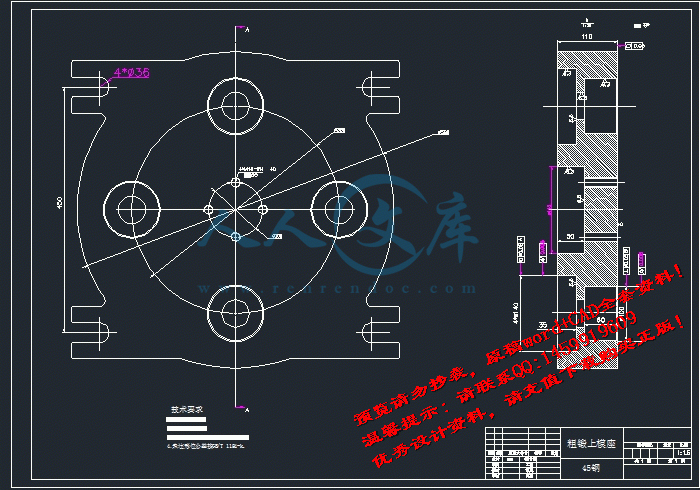
上模座.dwg
下模垫块.dwg
下模座.dwg
冲头.dwg
冲头固定板.dwg
凹模.dwg
压圈.dwg
压紧套圈.dwg
垫圈.dwg
垫圈2.dwg
垫板.dwg
导模.dwg
导模压圈.dwg
弹簧.dwg
弹簧垫圈.dwg
拉杆.dwg
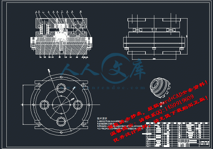
粗锻总装图.dwg
螺钉 (2).dwg
螺钉.dwg
顶杆.dwg
精锻
上模.dwg
上模压板.dwg
上模垫板.dwg
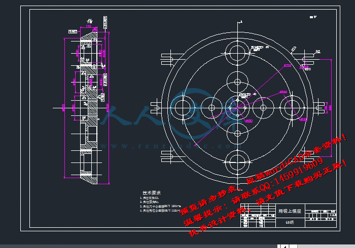
上模座.dwg
下模.dwg
下模压板.dwg
下模垫圈.dwg
下模座.dwg
冲头.dwg
冲头固定板.dwg
垫片.dwg
导套.dwg
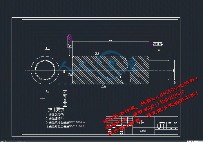
导柱.dwg
弹簧.dwg
拉杆.dwg
盖板.dwg
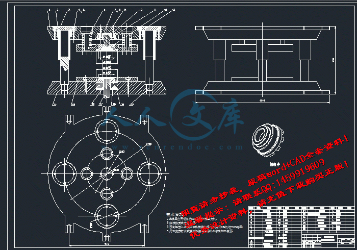
精锻总装图.dwg
螺钉.dwg
顶杆.dwg
外文文翻译
A0粗锻总装图.dwg
A0精锻总装图.DWG
A1粗锻上模座.DWG
A1粗锻下模座.DWG
A1精锻上模座.DWG
A1精锻下模座.dwg
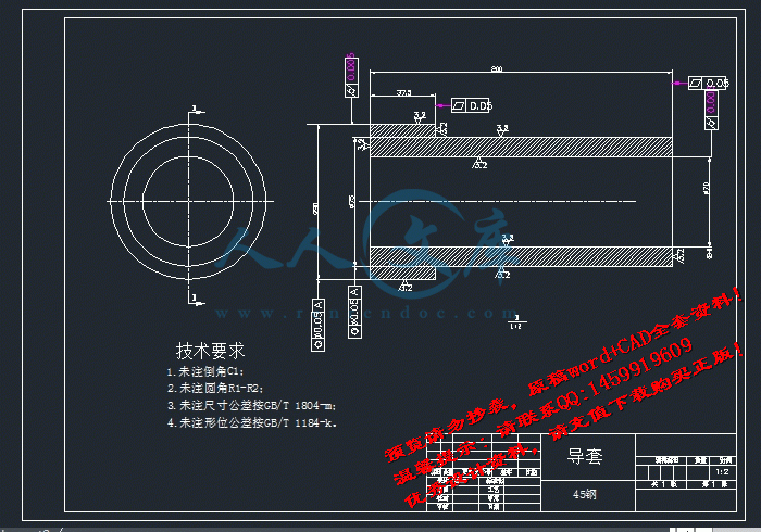
A3上模套圈.dwg
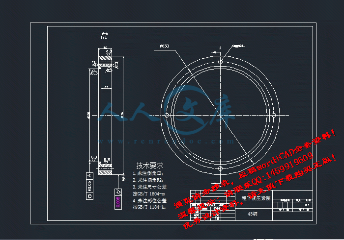
A3下模压紧圈.DWG
A3导套.DWG
A3导柱.DWG
粗装.png
精装.png
压缩包内文档预览:(预览前20页/共59页)
预览图 预览图 预览图 预览图 预览图 预览图 预览图 预览图 预览图 预览图 预览图 预览图 预览图 预览图 预览图 预览图 预览图 预览图 预览图 预览图
编号:480018    类型:共享资源    大小:6.40MB    格式:RAR    上传时间:2015-10-12 上传人:QQ14****9609 IP属地:陕西
45
积分
关 键 词:
汽车 离合器 精密 锻压 模具设计 锻造 铸造模具 课程毕业设计 汽车离合器精密锻压模具设计
资源描述:

汽车离合器精密锻压模具设计【优秀锻造模具全套课程毕业设计含10张CAD图纸】

【带任务书+开题报告+外文翻译】【62页@正文30500字】【详情如下】【需要咨询购买全套设计请加QQ1459919609】

A0粗锻总装图.dwg

A0精锻总装图.DWG

A1粗锻上模座.DWG

A1粗锻下模座.DWG

A1精锻上模座.DWG

A1精锻下模座.dwg

A3上模套圈.dwg

A3下模压紧圈.DWG

A3导套.DWG

A3导柱.DWG

任务书.doc

前期材料.doc

图纸目录.doc

外文文翻译

封面本.doc

开题报告.doc

摘要 目录.doc

正文.doc

粗装.png

粗锻

精装.png

精锻

任务书

毕业(论文)题目:    汽车离合器精密锻压模具设计      

任务书

1.本毕业设计(论文)课题应达到的目的:

(1)综合运用专业理论知识,提高资料的收集与分析能力;

(2)提高计算机综合应用能力;

(3)培养对工程图的识别与绘制能力;

(4)完成毕业设计的各个环节;

(5)撰写的论文要有条例,并努力提高学生的自学能力与独立分析与解决问题的能力。

1.本毕业设计(论文)课题任务的内容和要求(包括原始数据、技术要求、工作要求等):

内容:

(1)工件加工工艺分析;

(2)用Solidworks建立模具的三维总装图及其爆炸图;

(3)确定模具材料,设计整体结构;

(4)分析模具工作时的受力情况;

(5)完成毕业设计论文

要求:

(1)在分析工件加工工艺的基础上,设计模具;

(2)完成零件及模具的三维造型;

(3)充分阅读文献,收集已有的相关资料;

(4)论文要规范有条理,各有侧重,同时又相互配合,保质保量地完成毕业设计。

毕业设计(论文)任务书

3.对本毕业设计(论文)课题成果的要求(包括毕业设计论文、图表、实物样品等):

(1)实习报告;

(2)毕业设计(论文)开题报告;

(3)外文翻译;

(4)模具装配图与零件图;

(5)三维造型;

(6)设计说明书(论文);

4.主要参考文献:

1、机械设计手册

2、模具设计手册

3、模具图册

4、冲压工艺

5、Solidworks2007应用指导

摘    要

随着经济的发展,汽车已逐步成为人们日常生活中必不可缺少的工具。汽车的需求量在不断增长。在没有找到更好的替代品之前,对汽车而言汽车离合器一直将发挥着不可或缺的作用。汽车的性能与汽车离合器质量有着密切相关。因此怎样找到一种加工方法使离合器加工精度高,加工质量好,生产成本低是目前最重要的。而精密模锻是一种相对而言比较有优势的加工方法。针对啮合套结构特点,提出了模膛设计加工的要素及制造锻模齿形模的工艺,确定了其精锻成形工艺。在模具设计过程中,利用三维设计软件Solid Works完成了啮合套模具和零件的几何形状造型和二维工程图,通过AutoCAD对其二维工程图进行修改完善。

关键词:啮合套;加工方法;精密模锻;Solid Works

Abstract

As the economy develops, cars have gradually become an indispensable tool in daily life. The demand for automobiles is ever-increasing. Before an alternative could be found, the clutch will always play an essential role in cars—since the performance of a car is directly related to the quality of its clutch. Therefore, at this point, the most important task is to find a way in which clutches can be produced in high precision, superior quality, but at the same time, at a lower cost. Relatively speaking, the precision die forging process is a better method. Considering the structural characteristics of the meshing bush—the core structure of a clutch, this paper explains the constituent elements of designing mold chambers and the process of making bevel gear mold, which together decide both the design and making of the meshing bush’s precision die forging mold. The solid modeling software Solid Works was used to produce the geometric designs and 2-D engineering drawings of the mold and its product, facilitated by AutoCAD in revising and improving the 2-D drawings.

Keywords:clutch;mold;Processing method;Precision forging;Solid Works

目    录

摘要

Abstract

引言········································································1

第一章 模具的概述   ··········································· 2

1.1 模具的概念、作用和优点··········································  2

1.2 模具的分类和成形特点············································ 3

1.3 模具的加工方法和发展趋势 ········································7

1.4模具的材料选择  ················································  8

第二章  模锻生产工艺  ·····································  11

2.1 模锻成形方法  ············································ 11

2.1.1模锻成形过程 ········································11

2.1.2模锻时金属的流动方向判别································ 13

2.1.3模锻的分类    ······································ 13

2.1.4锻造工艺的基本工序和工步   ························· 14

2.2 模锻变形的力学与金属学基础  ····························· 18

2.2.1基本物理量  ·······································  18

2.2.2 塑性变形  ········································· 18

2.2.3塑性条件(屈服准则)   ····························· 19

2.2.4塑性变形体积不变条件   ····························· 20

2.2.5 塑变图············································· 20

2.2.6金属的塑性和塑性指标································ 21

2.3锻模的基本失效形式及外观检查······························ 22

2.4模锻工艺制定的主要内容   ································· 24

2. 4. 1 制定与模锻变形相关的工艺   ······················ 24

2. 4. 2  制定模锻变形前和变形后的工艺  ·················  25

2.5 模锻件图设计   ·········································· 26

2.5.1 分模面设计········································· 26

2. 5. 2 加工余量、锻件公差和锻造余块   ·················· 26

2. 5. 3 模锻斜度   ······································ 29

2. 5. 4 圆角半径   ······································ 30

2. 5. 5 冲孔连皮   ······································ 31

2. 5. 6飞边槽的设计  ····································· 31

2. 5. 7 技术条件   ·······································33

第三章 啮合套的精密锻压模具设计   ·······················34

3.1 课题主要设计内容   ·······································34

3.2主要设计步骤   ············································34

3.3具体设计分析计算···········································35

3.4预锻模膛设计···············································44

3.4.1 预锻模膛作用········································44

3.4.2 预锻模膛设计········································45

3.5 终锻模膛设计    ··········································45

3.6 原毛坯尺寸的确定··········································47

3.7 模锻变形前的热处理工序····································48

3.7.1加热的目的   ········································48

3.7.2加热的方法    ·······································48

3.7.3锻件温度的选择  ·····································49

3.7.4锻件的冷却      ·····································50

3.7.5钢在加热过程中的物理、化学变化························50

3.8模具材料的选择 ···········································51

第四章 模具的三维实体造型·····································53

4.1 Solid Works功能简介········································53

4.2 SolidWorks三维造型·········································53

第五章  总结 ···················································56

致谢    ·················································57

附录:参考文献    ·······································57

引言

锻造是金属加工方法之一,在现代制造业中占有重要地位。锻造一般属于体积成形,是通过金属体积的转移和分配,来获得机械零件或接近于零件尺寸的毛坯,锻造的产品称为锻件。模锻是适合于大批量生产锻件的锻造方法。模锻时,使用特制、开设有与锻件形状一致或相近的型腔(模膛)的锻模,将锻模安装在锻造设备上,金属毛坯置于锻模的模膛中,锻造设备通过锻模对毛坯施加载荷,是毛坯产生塑性变形,同时变形流动又受到模膛空间的限制。

金属材料通过模锻塑性成形,可以获得形状尺寸精确、表面光洁程度较高的锻件,同时其内组织能够得到显著改善,使用性能得到提高。并且,模锻具有很高的生产率,模锻件机械加工余量较小,材料利用率较高;锻件流线分布合理,零件使用寿命高;生产操作简单方便。在工程应用中承受较大或复杂载荷的零件,常采用模锻方法进行大批量生产。

模锻成形在国民经济各个领域中得到广泛应用。例如汽车、拖拉机、机械、航空、航天、军工等领域,某些需要考虑形状尺寸和内部质量的稳定性,以及有某些特殊性能要求的零件,也经常采用模锻方法生产。由于社会需求和生产技术的进步,各种先进的、特殊的模锻方法不断产生和发展。例如精密模锻、液态模锻、粉末锻造、摆动辗压、自动辗环、高速模锻、超塑模锻等,所加工的材料,也从普通钢和一般的有色金属,发展到特殊钢、高温合金、铝镁合金、复合材料等。

参考文献:

[1]李小明,李彦生,韩景芸,陆丽丽等.·一种新的精密高效低成本模具加工与成形方法·模具工业,2006,·32(8):

[2]金康,陈东,褚作明,王晓辉.·新型热精锻专用模具钢的成分设计及热处理工艺·金属热原理,2011,·36(4):·

[3]刘颖.·我国机械产业模具技术的现状及未来前景·现代营销(学苑版),2011(12)

[4]王晶.·模具材料的分类及其应用·工程技术科技资讯,2010(08)

[5]模具加工新方法[J]. 模具制造,2004,(09)

[6]卢险峰.·关于模具的一级分类问题·中国机械工程,2002,·22:

[7]李海平.·国内模具工业的现状及研发趋势[J]·科技资讯,2006,(26):

[8]祝新.·模具加工技术的一些新进展[J].·洪都科技,1998,(03) .

[9]张海渠.·模锻工艺与模具设计·北京:化学工业出版社,2009.10 70~100

[10]高为国.·模具材料·北京:机械工业出版社,2005.

[11]傅建军.·模具制造工艺·北京:机械工业出版社,2005.

[12]模具实用技术丛书编委会·模具材料与使用寿命·北京:机械工业出版社,2000.

[13]程里.·模锻实用技术·北京:机械工业出版社,2010.3 55~60

[14]罗秀文.·模锻工工艺学·北京:科学普及出版社,1984.5 1~3

[15]吕炎.·锻造工艺学[M]·北京:机械工业出版社,1995.

[16]张志文.·锻造工艺学[M]·北京:科学普及出版社,1983.

[17]李永堂等.·锻压设备理论与控制[M]·北京:国防工业出版社,2005.

[18]李冬.·国内模具行业的现状及发展趋势[J]·成都航空职业技术学院学报·2005,(02)

[19]编著责任者不祥.锻压模设计[M].北京.机械工业出版社,1984.

[20]作者不详.高速加工技术及其在模具制造中的应用[J]?.出版地、出版社不祥.2008

[21]作者不详.面向模具制造系统的电火花线切割DNC系统研究[J].出版地、出版社不祥.2009

[22]作者不详.模具制造领域中的表面工程技术应用综述及展望[J].出版地、出版社不祥.1972

[23]罗薇红.Auto CAD与模具设计[J].出版地、出版社不祥.2000

[24]李德有.RTM模具的手糊制作[J].出版地、出版社不祥.2000

[25]袁根华.绿色的模具[J] .出版地、出版社不祥.1972

[26]余小鲁.绿色制造技术在模具中的应用[J].出版地、出版社不祥.1998

[27]彭建声,秦晓刚.模具技术问与答.第二版.北京:出版社机械工业出版社.2003

[28]中国锻压协会.锻造模具与润滑[M].北京.国防工业出版社,2010.

[29]模具实用技术丛书编委会.模具材料与使用寿命[M].北京.机械工业出版社,2000.

[30]编著责任者不祥.锻工手册[M].北京:机械工业出版社,1978.

[31]编著责任者不祥.精密锻造[M].北京:机械工业出版社,1985.

[32]陈锡栋,.周小玉.实用模具技术手册.北京:机械工业出版社,1985.

[33]锻模设计手册编写组.锻模设计手册[M].北京.机械工业出版社,1991.

[34]孟繁杰,彭其风.模具材料[M].北京.机械工业出版社,1989.

[35]高为国.模具材料[M].北京.机械工业出版社,2005;

[36]林法禹.特种锻压工艺[M].北京.机械工业出版社,1991.


内容简介:
Description and Smoothing of NC Motion Path Based on the Cubic Trigonometric Interpolation spline Jianming Tao1,a , Aiping Song 1,b and Danping Yi 1,c 1College of Mechanical Engineering, Yangzhou University, Yangzhou 225127, China , bapsong, Keywords: Spline Curve; Interpolation; Adjustable Shape; Trajectory Description; Smooth Path Abstract. In order to better describe the complex motion path of NC machining and realize the smooth transition between path segments, a kind of cubic trigonometric interpolation spline curve was put forward based on a set of special basis function. The spline curve which with adjustable shape satisfies the 1C continuity and it can accurately describe some common engineering curves such as straight line, circular arc and free curve. According to the given information of control points, different shapes of interpolation spline curve can be gotten by changing the adjustment coefficients. Through selecting proper control points and shape adjustment coefficients near the corner, insert the spline curve can realize the smooth transition at the corner of adjacent NC motion path segments, which can ensure the stability of motion path and the continuous of feed speed. Meanwhile, it also can reduce the impact to NC machine. Introduction High-speed NC machining is the important way to improve efficiency and quality of parts machining. During the high-speed operation process of machine tool, it needs to ensure the stability of machine tool movements to avoid generating larger impacts which will affect the quality of parts machining, meanwhile to protect the machine tool feeding system 1. In actual machining process, NC motion paths often consist of a number of straight lines and circular arcs. At present, to deal with the speed at the corner of adjacent NC machining path segments, the main method is to slow down the speed to zero at the end of the current processing segment, and then accelerate to command speed in the starting position of the next processing segment. Using this way to get through each corner with zero speed can avoid larger impacts to NC machine. However, this way will cause frequent start and stop of speed during the machining process, and it will seriously affect the improvement of parts machining efficiency 2. Therefore, it needs to study new motion control method at the corner, which can make the transfer speed does not drop to zero, and reach the purpose of realizing the high-speed smooth transition between two adjacent path segments. Thus to improve the machining efficiency and limit the impact loads. In dealing with the speed at the corner of adjacent machining path segments, literatures 3,4 proposed to add circular arc or quadratic curve for corner transition, in order to make the speed does not drop to zero. To a certain extent, this method improved the machining efficiency and reduced the impacts to machine tools. But it lacks the control of acceleration and the error control is not strict; when the corner is larger, the improvement of transfer speed will be limited, so this method does not well meet the needs of high-speed machining. Literature 5 put forward a speed control method with look-ahead; this method limited the impacts formed by the change of velocity vector at the corner; through the limited speed dropping at the corner to pursue the maximum machining efficiency. But it needs a large amount of pre-computation and it requires higher numerical control system. Literature 6 proposed a vector method to realize the smooth transition between two path segments. Through the anticipatory analysis of the motion parameters, this method can improve the transfer speed when the corner is larger; but when the corner is smaller, the transfer speed is still not smooth enough. Applied Mechanics and Materials Vols. 365-366 (2013) pp 515-521Online available since 2013/Aug/16 at (2013) Trans Tech Publications, Switzerlanddoi:10.4028/AMM.365-366.515All rights reserved. No part of contents of this paper may be reproduced or transmitted in any form or by any means without the written permission of TTP,. (ID: 03, Yangzhou University, Yangzhou, China-27/02/14,06:23:35)nts On the basis of cubic Hermite interpolation function7,8, this paper puts forward a kind of adjustable shape cubic trigonometric polynomial interpolation spline curve, which can be used to describe the NC machining paths, such as straight line, circular arc and free curve segments, and it has properties of simple calculation, flexible structure, etc. The spline can also be used to describe the smooth transition curves at the corner and realize the high-speed smooth transition between NC machining path segments, which meets the needs of modern numerical control system for high-speed, stability and flexibility. Cubic Trigonometric Interpolation Spline Curve Basis Function of Spline. For any given value of variables and k , parameter u satisfies 0 1u ; the following formula is called a set of cubic trigonometric spline basis function. ( ) ( ) ( ) ( )( ) ( ) ( )3 3 20,33 3 21,33 3 22,33,32 2 2 2 2( ) (1 ) ( ) (1 )2 2 2 2 2 2 2 2( ) 1 (1 ) (1 ) 1 ( 1) 1 1 12 2 2 2 2 2 2 2( ) 1 1 1(B u C S S SB u k C k S k S C k S kB u k k C k k S S k C kS kB = + + + = + + + + + + + + + + + = + + + + + + 3 3 22 2 2 2)u kC k S k S kC = + +(1) In formula: S is stand for ( )sin 2u , C is stand for ( )cos 2u . Interpolation Spline Curve. Suppose that the group of given control points are iq ( 0,1, ni = , ), then the spline curve segments can be defined as: ( ) ( )3 ,30i i j jjP u q B u+= , 0 1u , 0,1, 3i n= , . (2) The curve ( )P u which is composed of all small curve segments ( )iP u is called the cubic trigonometric interpolation spline curve. From expression (2), it is easy to know that the whole curve ( )P u formed by 2n segments of small curves. To number i segment curve ( )iP u exists: ( ) ( ) ( ) ( )( ) ( ) ( ) ( )1 2 11 2 1 3 20 , 01 , 1i i i i i i ii i i i i i iP q P q q k q qP q P q q k q q+ + + + + + += = = = . (3) And to number 1i + segment curve ( )1iP u+ exists: ( ) ( ) ( ) ( )( ) ( ) ( ) ( )1 1 1 2 1 3 21 2 1 3 2 4 30 , 01 , 1i i i i i i ii i i i i i iP q P q q k q qP q P q q k q q+ + + + + + + + + + + + += = = = . (4) Comparing formula (3) with (4), it can be obviously found that the adjacent curves ( )iP u and ( )1iP u+ have the following connections: ( ) ( )( ) ( ) ( ) ( )1 11 2 1 3 21 0 1 0i i ii i i i i iP P qP P q q k q q+ + + + + += = = . (5) According to formulas (3), (4) and (5), a theorem can be gotten, that is the spline curve ( )P u interpolates the group of given control points from 0q to 2nq and it also satisfies 1C continuity. Spread out the spline curve expression (2) into a polynomial form, then can get: 516 Machine Design and Manufacturing Engineering IInts ( ) 3 3 23 3 21322 2 2 2 2(1 ) ( ) (1 )2 2 2 2 2 2 2 2( 1) (1 ) (1 ) ( 1) ( 1) ( 1) ( 1) 12 2 2 2( 1) (iiiu C S S Sk C k S k S C k S kk k C k k + = + + + + + + + + + + + + + + + + + + + P qqq 3 23 3 232 2 2 21) ( 1)2 2 2 2iS S k C kS kkC k S k S kC + + + + + + + q; (6) 3 3 23 3 21322 2 2 2 2(1 ) ( ) (1 )2 2 2 2 2 2 2 2( 1) (1 ) (1 ) ( 1) ( 1) ( 1) ( 1) 12 2 2 2( 1) ( 1)iiiX x C S S Sx k C k S k S C k S kx k k C k k + = + + + + + + + + + + + + + + + + + + + 3 23 3 233 3 23 3 212 2 2 2( 1)2 2 2 22 2 2 2 2(1 ) ( ) (1 )2 2 2 2 2 2( 1) (1 ) (1 ) ( 1) ( 1)iiiS S k C kS kx kC k S k S kCY y C S S Sy k C k S k S C + + + + + + + = + + + + + + + + + + + + 3 3 223 3 232 2( 1) ( 1) 12 2 2 2 2 2 2 2( 1) ( 1) ( 1)2 2 2 2iik S ky k k C k k S S k C kS ky kC k S k S kC + + + + + + + + + + + + + + . (7) In formulas (7) and (8): S is stand for ( )sin 2u , C is stand for ( )cos 2u , 0 1u . (a) (b) Fig. 1 Adjustable shape interpolation spline curve From above can know, any four given control points completely determine a segment of adjustable shape cubic trigonometric interpolation spline curve. The curve interpolates the first two control points, and the latter two control points are used to calculate the endpoint slopes of the curve segment. Setting iq , 1iq + , 2iq + , 3iq + respectively as A , B , C , D four assured points, adopting AutoLISP programming in the AutoCAD can draw a segment of adjustable shape cubic trigonometric interpolation spline curve, as shown in Fig. 1. Changing the value of and k can realize the shape adjustment of the curve segment. The four curves in Fig. 1(a) respectively corresponding to the spline curve segments when k takes a certain value of 0.5, 0 = , 0.5, 1 and 1.5; while the four curves in Fig. 1(b) respectively corresponding to the spline curve segments when takes a certain value of 1, 0.3k = , 0.5, 0.6 and 0.7. Fig. 2 Ring interpolation spline Fig. 3 Straight line interpolation spline Furthermore, ring form interpolation spline curve can be generated when the control points are reused. As shown in Fig. 2, when the control points sequence is (B, B, C , D), i.e. point B is reused, then through programming can generate the ring spline curve segments. The three ring curves in Fig. Applied Mechanics and Materials Vols. 365-366 517nts 2 respectively corresponding to the spline curve segments when k takes a certain value of 1 , 1 = , 0, and 1. Keeping the three points A, B, C locate in one straight line, then the starting point vector of the ring spline is in the same direction with AB , and the end point vector is in the same direction with BD. This feature can be well used to deal with the corner smooth transition between adjacent path segments in NC machining. Engineering Application of the Cubic Trigonometric Interpolation Spline Curve Compared with the traditional Ferguson curve, Bezier curve and B-spline curve, the adjustable shape cubic trigonometric interpolation spline curve has better properties. It not only has the properties of interpolation and shape adjustable, but also because the expression of the spline curve contains trigonometric polynomial, by choosing proper control points and shape adjustment coefficients, the spline curve can accurately describe the common engineering curves such as straight line, circular arc and free curve, etc. Therefore, the spline curve can be used to describe the complex NC motion paths; meanwhile, through selecting proper control points near the corner of adjacent machining path segments and shape adjustment coefficients, it can generate the ring form or circular arc spline curve which can realize the high-speed smooth transition around the corner. Straight Line Description of NC Motion Path. Suppose the two endpoints of a line segment are B and C , taking the four control points as sequence as (B,C ,B,C ), then a straight line from B to C can be constructed as shown in Fig. 3. Analyze formula (7), when 22i ii ix xy y+= = , 3 13 1i ii ix xy y+ + += = , 0 = and 1k = , formula (7) turns into the linear parameter equation: ( )( )31 131 1i i ii i iX x x C xY y y C y+ + + = + = +. (8) In formula: C is stand for ( )cos 2u , 0 1u . Circular Arc Description of NC Motion Path. Using the spline curve by taking four special control points and shape adjustment coefficients can accurately describe the circular arc. Suppose the two endpoints of a circular arc segment are A and B, taking four continuous control points as ( ),0A a , ( )0,B a , ( ), 2C a a and ( )2,D a a , shape adjustment coefficients as 1 = , 1k = , then a circular arc from A to B can be constructed. Put the above four control points coordinates and shape adjustment coefficients into formula (7), the parametric equation of circular arc can be gotten: X a CY a S= =ii . (9) In formula: S is stand for ( )sin 2u , C is stand for ( )cos 2u , 0 1u . Fig. 4 shows the circular arc segment with center angle of 90, which corresponding to the change of parameter u from 0 to 1. When using the spline curve to describe circular arc with center angle less than 90, it can be done through the control of the value of parameter u ; and when to describe circular arc with center angle more than 90, using a few circular arc segments joining together to realize. Free Curve Description of NC Motion Path. Using this cubic trigonometric interpolation spline can easily describe the free curve. From above we know that n given control points can construct 3n segments of spline curves. As shown in Fig. 5, through ( A, B, C , D, E , F , G , H , I , J ) ten control points can generate a segment of free curve which formed by seven segments of small spline curves. And the whole free curve satisfies 1C continuity, which ensures the smoothness of the spline curve. 518 Machine Design and Manufacturing Engineering IInts Fig. 4 Circular arc interpolation spline Fig. 5 Free curve interpolation spline Planning of NC Motion Path. Fig. 6 shows a part of the current commonly used motion path in NC machining. The moving path of tool center is A B C D . During the motion path, points B and C are sharp turning points. When the corner angle formed by adjacent machining path segments is larger, it will cause oversized changes of movement velocity vector, which will be easier to cause larger impacts to NC machine tools. This phenomenon is especially more obvious under the circumstance of high-speed machining. According to the properties of the spline curve, inserting the spline at the corner of adjacent machining path segments, can generate the trajectories of corner transition and realize the smooth transfer between machining path segments, so as to achieve the purpose of smoothing corner transition speed. Fig. 6 NC motion path before smoothing Fig. 7 NC motion path after smoothing Fig. 7 shows the described NC motion path based on the adjustable sharp cubic trigonometric interpolation spline curve. Among them, points 1C and 2C are the intersections of tool outer contour line with segments BC and CD when the tool center is at point C . Segments AB , 1BC , and 2C D are straight lines, insert a ring form spline transition curve outside the corner point B and circular arc spline transition curve inside the corner point C . Such planned NC machining motion path is smooth, and there is no speed drop and rise during the corner transition, which can guarantee the smooth transfer around the corner, and easy to realize the high-speed smooth machining between NC motion path segments. Smoothing of External Corner. As shown in Fig. 8, in order to smooth transfer the machining segments between ml and nl , a ring form spline curve is inserted at the external corner point B, which is generated by the four control points with sequence as ( B , B , 1B , 2B ) and shape adjustment coefficient as 1k = . Among them, point 1B is on the extension cord of segment ml and point 2B is on the segment nl . Selecting the control points as this way can ensure that the starting point vector of the spline transfer curve is in the same direction with segment ml , and the end point vector is in the same direction with segment nl , which can realize the external corner smooth transition between NC motion path segments. Change the value of shape adjustment coefficient can generate different sizes of spline curves, so through choosing proper value of can control the change of acceleration during the corner movement process. Applied Mechanics and Materials Vols. 365-366 519nts Fig. 8 External corner smooth transition Fig. 9 Internal corner smooth transition Smoothing of Internal Corner. As shown in Fig. 9, a circular arc spline curve is inserted at the internal corner point C to smooth transfer the segments between nl and ol . The four continuous control points are ( 1C , 2C , 3C , 4C ) and shape adjustment coefficient 1k = . Among them, points 1C and 2C are the intersections of tool outer contour line with segments nl and ol when the tool center is at point C ; point 3C is on the extension cord of segment nl , point 4C is on the segment ol , and their coordinates are determined by points 1C and 2C . Similarly, the starting point vector of this curve is in the same direction with segment nl and the end point vector is in the same direction with segment ol , which can realize the internal corner smooth transition of NC motion path segments. Change the value of shape adjustment coefficient can change the size of the transfer curves, so through choosing proper value of can control the change of accelera
温馨提示:
1: 本站所有资源如无特殊说明,都需要本地电脑安装OFFICE2007和PDF阅读器。图纸软件为CAD,CAXA,PROE,UG,SolidWorks等.压缩文件请下载最新的WinRAR软件解压。
2: 本站的文档不包含任何第三方提供的附件图纸等,如果需要附件,请联系上传者。文件的所有权益归上传用户所有。
3.本站RAR压缩包中若带图纸,网页内容里面会有图纸预览,若没有图纸预览就没有图纸。
4. 未经权益所有人同意不得将文件中的内容挪作商业或盈利用途。
5. 人人文库网仅提供信息存储空间,仅对用户上传内容的表现方式做保护处理,对用户上传分享的文档内容本身不做任何修改或编辑,并不能对任何下载内容负责。
6. 下载文件中如有侵权或不适当内容,请与我们联系,我们立即纠正。
7. 本站不保证下载资源的准确性、安全性和完整性, 同时也不承担用户因使用这些下载资源对自己和他人造成任何形式的伤害或损失。
提示  人人文库网所有资源均是用户自行上传分享,仅供网友学习交流,未经上传用户书面授权,请勿作他用。
关于本文
本文标题:汽车离合器精密锻压模具设计【优秀锻造模具全套课程毕业设计含10张CAD图纸】
链接地址:https://www.renrendoc.com/p-480018.html

官方联系方式

2:不支持迅雷下载,请使用浏览器下载   
3:不支持QQ浏览器下载,请用其他浏览器   
4:下载后的文档和图纸-无水印   
5:文档经过压缩,下载后原文更清晰   
关于我们 - 网站声明 - 网站地图 - 资源地图 - 友情链接 - 网站客服 - 联系我们

网站客服QQ:2881952447     

copyright@ 2020-2025  renrendoc.com 人人文库版权所有   联系电话:400-852-1180

备案号:蜀ICP备2022000484号-2       经营许可证: 川B2-20220663       公网安备川公网安备: 51019002004831号

本站为文档C2C交易模式,即用户上传的文档直接被用户下载,本站只是中间服务平台,本站所有文档下载所得的收益归上传人(含作者)所有。人人文库网仅提供信息存储空间,仅对用户上传内容的表现方式做保护处理,对上载内容本身不做任何修改或编辑。若文档所含内容侵犯了您的版权或隐私,请立即通知人人文库网,我们立即给予删除!