DynamicAnalysisofFour_省略_ismwithJointCle.pdf

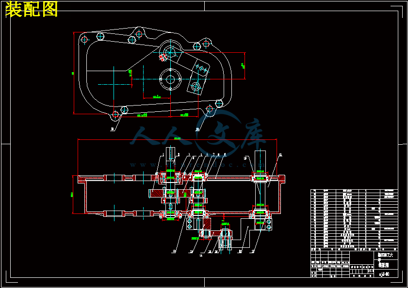
椭圆齿轮-曲柄摇杆打纬机构的分析与设计【3D-PROE】【16张CAD图纸和说明书】

收藏

资源目录
跳过导航链接。
椭圆齿轮-曲柄摇杆打纬机构的分析与设计【3D-PROE】【16张CAD图纸和说明书】.zip
毕业设计说明书.doc---(点击预览)
文献综述.doc---(点击预览)
开题报告.doc---(点击预览)
任务书.doc---(点击预览)
PDF图纸
三维图纸
sanweitu
99.asm.1
99.asm.2
AnalysisDefinition10.fra
AnalysisDefinition10.pbk
error.chk
prt0001.prt.1
prt0002.prt.1
prt0003.prt.1
prt0004.prt.1
prt0005.prt.1
prt0006.prt.1
prt0006.prt.2
prt0006.prt.3
prt0006.prt.4
prt0006.prt.5
prt0007.prt.1
prt0007.prt.10
prt0007.prt.11
prt0007.prt.12
prt0007.prt.13
prt0007.prt.14
prt0007.prt.2
prt0007.prt.3
prt0007.prt.4
prt0007.prt.5
prt0007.prt.6
prt0007.prt.7
prt0007.prt.8
prt0007.prt.9
std.out
trail.txt.1
current_session.pro
drw0002_dwg__out.log.1
drw0004_dwg__out.log.1
prt0001.prt.1
prt0002.prt.1
prt0003.prt.1
prt0004.prt.1
prt0005.prt.1
prt0006.prt.1
prt0007.prt.14
trail.txt.1
材料
翻译
表格
1.JPG
2.JPG
3.jpg
4.jpg
5.jpg
6.jpg
7.jpg
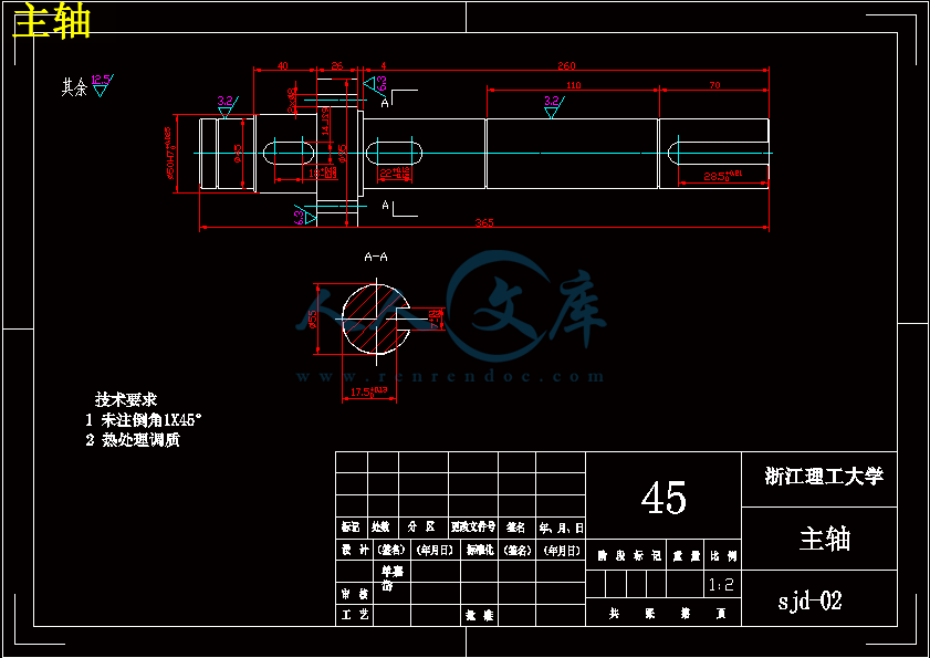
主轴.dwg
从动轴.dwg
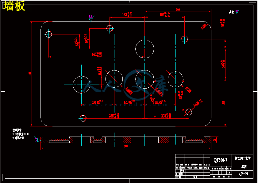
墙板.dwg
挡圈1.dwg
挡圈2.dwg
挡圈3.dwg
摇杆-左.dwg
摇杆.dwg
曲柄.dwg
曲柄座.dwg
椭圆齿轮.dwg
箱体.dwg
装配图.dwg
输出轴.dwg
连接轴.dwg
连杆.dwg
压缩包内文档预览:
预览图 预览图 预览图 预览图 预览图 预览图 预览图
编号:6040022    类型:共享资源    大小:41.74MB    格式:ZIP    上传时间:2017-10-27 上传人:俊****计 IP属地:江苏
40
积分
关 键 词:
椭圆 齿轮 曲柄 摇杆 打纬 机构 分析 设计 3d-proe 16张 cad 图纸 说明书
资源描述:

摘要

目前在织机中有三种类型:分别是剑杆织机、喷水织机和喷气织机,剑杆织机因结构简单,成本低而应用广泛。我国是一个纺织大国,但由于我国在现代剑杆织机研究不足,当今剑杆织机机构的知识产权不在我国,就不可能将企业做大、做出品牌。要改变中高级剑杆织机生产设备主要依靠进口的局面,必须走自主创新的道路,需要从剑杆织机核心机构开始做基础性研究工作。剑杆织机的打纬机构主要有三种:共轭凸轮机构、四连杆机构和六连杆机构。

本文综述了目前国内外织机发展的现状和打纬机构的研究情况,提出了一种新的打纬机构:椭圆齿轮-曲柄摇杆打纬机构。为分析该机构的打纬性能,建立了机构的运动学数学模型,列出位移、速度和加速度方程。采用Visual Basic 6.0软件编写了辅助分析软件,得到打纬机构的运动学特性曲线。

了解和分析机构参数对运动规律的影响,通过对机构运动目标的确定,来优化打纬机构的各参数,本文采用基于VB6.0编写的可视化软件进行人机交互对话优化方法,结合实际设计时的结构限制,取得了一组最佳参数。

关键字:打纬机构;椭圆齿轮;曲柄摇杆;运动学分析;参数分析


Abstract

At present,there are three types looms,namely the rapier,water and air-jet looms,rapier has broad application because of its simple structure and low cost.China is a big textile country,but because lacking research in modem rapier,rapier in today’s intellectual property is not in our country,which restricted the domestic enterprises become strong and make famous brand,to change the situation that high product equipment of rapier mainly depends on imports,must take the road of independent innovation and should start do basic research from core component of the rapier.Rapier of the beating—up mechanism has three main types:conjugate cam,four-bar linkage and six—bar linkage.

This paper reviewed the current development of looms boom domestic and foreign and also the situation of the beating-up mechanism study,present a new type beating-up mechanism:elliptical gear—crank-rocker beating—up mechanism,and then establish the kinematics mathematical model of beating—up mechanism,and the equation of displacement ,velocity and acceleration will be list,for analysis the performance of beating—up mechanism,kinematics analysis of the new beating-up mechanism was made with Visual Basic 6.0 software,output beating-up mechanism’s kinematics curve.

Understand and analyses the effect of parameters on law of motion, by exterminating the target of mechanism motion, based on the visualization software of VB6.0 for interactive dialogue optimization methods,obtained a set of best Parameters with the structure restrictions while doing actual design.

Key words:beating--up mechanism;elliptic gear;crank-rocker;kinematics analysis;parameter analysis ;


目  录

摘  要

Abstract

第一章 绪论 1

    1.1引言......................................................................................................................................1

    1.2几种典型的打纬机构 2

1.2.1 概述 2

1.2.2 四连杆打纬机构 2

1.2.3 六连杆打纬机构 5

1.2.4 共轭凸轮打纬机构 6

1.3打纬机构国内外研究现状 7

第二章 椭圆齿轮-曲柄摇杆打纬机构运动学建模 8

2.1椭圆齿轮一曲柄摇杆打纬机构简介 8

2.2机构运动学目标 8

2.3椭圆齿轮一曲柄摇杆的打纬机构运动学模型的建立 9

2.3.1从动椭圆齿轮角位移、角速度和角加速度数学模型建立 9

2.3.2摇杆的角位移、角速度和角加速度数学模型建立 11

2.3.3 打纬点的角位移、角速度和角加速度数学模型建立 12

第三章 辅助分析软件的功能及其使用方法 14

3.1 打纬机构运动学辅助分析初始界面 14

    3.2打纬机构运动学辅助分析运行界面 15

3.3 打纬机构运动学辅助分析模拟界面 15

3.4进步界面 16

第四章 机构参数对运动规律的影响 18

4.1 椭圆偏心率k的影响 18

4.2 初始安装角δ的影响 18

4.3 曲柄、连杆长度的影响 19

4.4 摇杆运动性能分析 20

第五章 机构的结构设计 22


5.1 箱体的设计 22

5.1.1 箱体的结构约束 22

5.1.2 新机构参数的选择 23

5.1.3 箱体的结构设计 23

5.2 椭圆齿轮的三维模型建立 24

5.3 曲柄的设计和图纸 25

5.4 摇杆的设计和图纸 26

5.5轴的设计和图纸 27

5.5.1 轴的材料选择 27

5.5.2 轴的结构设计 27

5.5.3提高轴的强度措施 28

5.5.4 轴的强度校核 29

5.6 三维装配图 29

第六章 总结 31

参考文献 32

致  谢 33


第一章 绪论

1.1引言

我国是纺织大国,纺织品的出口量位居世界第一,同时也是纺织机械进口大国,据我国海关统计,2011年1-11月我国纺织机械进出口总额为53.83亿美元,同比增长59.56%。其中进口金额为38.1亿美元,纺织机械出口金额为15.73亿美元[1]。在1:3的纺织机械中,织机位居第二,为5.29亿美元,占18.14%,同比增长17.86%,主要是喷气织机、剑杆织机和片梭织机。2008年上半年我国纺织机械及其零附件出口额8.10亿美元,同比增长6.60%,6月出口额为1.28亿美元。2010年1-11月我国纺织机械进出口额为38.10亿美元,同比增长65.69%。

我国有不少织机生产厂家,但其产品大多是中低档水平,且没有形成世界知名品牌。虽然有一些厂家开始生产高档织机,如中国纺织机械集团有限公司和经纬纺织机械股份有限公司,但其产品在可靠性和耐久性方面却远远不如进口产品,特别是不能长时间高速运转(在演示和展销期间可以高速运转),究其原因, 

除了关键零部件的材质和热处理不过关外,对核心工作部件的工作机理没有进行深入的研究,造成运动构件之间受力不良也主要原因之一。因此虽国内机织在价格上具有优势(如国产剑杆织机价格平均在12万元/台,而2010年进口的剑杆织机平均价格为5.45万美元),但很多企业还是青睐进口产品。

出现这种状况的原因是,国内织机厂家自主创新能力差。到2004年4月,在我国申请有关剑杆织机机构的相关专利共35件,其中国外在华侨申请11件,且这11件已经进入实用和推广。国内企业对核心机构(如打纬和引纬机构)的研究还停留在测绘和仿制阶段,这不仅带来侵权法律问题,不可能将企业做大、做出品牌,同时也由于没有从理论上进行深入研究,对其中的核心技术没有完全掌握,就仿制不了预想的性能和可靠性。可见织机的研究必须走自主创新的道路,必须从核心执行机构创新开始,运用计算机分析软件获得最佳参数,取得自主知识产权,然后再研究其工作机理、优化性能和提高可靠性,才能创自己的品牌和名牌产品。


1.2几种典型的打纬机构

1.2.1 概述

打纬机构是织机的主要机构之一,作用是将织机主轴的匀速旋转运动转化为摇轴的非匀速摆动,把新引入的纬纱推向织口形成织物,要求钢扣在后心位置要有停顿时间或“近似停顿”时间,以便有充分的时间完成打纬运动。

为了实现理想的打纬运动,并使打纬机构符合织造工艺要求,达到最佳经济

效益,对打纬机构的工艺要求如下:


内容简介:
Dynamic Analysis of Four-Bar Beating-up Mechanism with Joint ClearanceXUE Wen-liang()1* , CHEN Guo-zhen(S) 2, CHEN Ge( )3, ZHU Zhang-chen(c7)1, CHENG Long-di(H) 11 Key Laboratory of Textile Science & Technology, M inistry of Education, Donghua University, Shanghai201620, China2 Shanghai ShenAn Textile Co. , Ltd. , Shanghai200020 , China3 College of Mechanical Engineering, Donghua University, Shanghai201620, ChinaAbstract: For the four-bar beating-up mechanism of air-jetloom, the plain bearing of linkage is the bearing withdynamicload, and is immersed in the lubricant-box. If thejoint clearance is considered, the research on linkagemovement could be very complicated. In this paper, thekinematic characteristics of four-bar beating-up mechanismwith joint clearance were studied by analyzing the trace ofjournal center and the balance of radial, tangential forces,andbearing load. The region of principal vibration and itsforming causes were discussed. And the results couldinterpret the measuring curves of four-bar beating-upmechanism completely.Key words : dynam ic a na lysis ; fo ur-bar linkage ; beat ing-upmechanism ; joint clear anceCLCnumber: T S193. 3 Document code: AArticleID: 1672- 5220( 2010) 04- 0559- 07Introductio nFo r the fo ur- bar beating- up mechanism, the crankshaf t bear ing and ro ckshaf t be ar ing are the ball bear ing ,and the co uple journal bear ing and cra nk jo ur nal be ar ingare the jo ur nal bear ing. T he cr ank, co uple r, r o cke r, a ndtwo journal bear ings a re a ll immer ged in the lubricant, a ndthere is the ra dial clea rance betw een the ring and pin o fjo ur nal bea ring. T he cle ar ance is helpf ul to the r elativemo tio n o f links by pr o viding the space o f mo ving a ndlubr ica ting, but it also leads to the disc ontinuo us mo tion o fkinema tic pair, w hich is the m ain r eason to a ffe ct themechanism dynamic char acter istics 1-3 . Fo r themechanisms tr ansf err ing the fo r ce and m oment a pplied inthe industr y manufa ctur ing, as t he joint clear ance enlar g ingthe dynamic chara cter istics will be destr uct ive unde r theconditio n of high spee d a nd high load.T he jo int cle ara nce o f fo ur- bar beating- up mechanismis w ithin the r ange o f t olera nce . I f r unning sm oo thly so meclea rance in the jo int of me ch anism is alw ays necessa ry .But the cle ar ance is o ften incr eased by w ear ing , then theimpact f or ces c ould cause the v ibra tio n, no ise, bear ingde ter io ra tio n, a nd the we ar co uld a lso be incr eased.T here fo re , the v ibr ations becom e one basic study conte ntabout mechanism kine tics. X i et a l . studied the re lat io nbe twee n the dy namic balance a nd the v ibra tio n4 , andSo o ng et al . studie d the dy namic char acter istics o f cr ank-slider w ith jo int clear ance 5 .T he dynam ic alter nating lo ad is endured by the jo ur nalbe ar ing of fo ur- bar be ating- up mechanism. T he f or ces o flinks ar e tr ansfer r ed by the o il f ilm, and the pin center o fco uple jo ur nal mo ve s on the trace . When the eccentr icity islittle, the mot io n o f ro cker is unstable, w hich sho uld le adto the instantaneo us impact betw een the r ing a nd the pinand m or e ser ious we ar, so the str o ng vibr at io n w ill happe nmo re f re quently.1 Fo ur-Bar Linkage w ith Jo int ClearanceIf the jo int clear ance o f mechanism is zer o , thecenter s o f be ar ing and jo ur na l ar e in the same position. Butif the clear ance appear s, tw o center s will be separ ated,which can re sult in the ecce ntricity , and ther e is the ex trade gr ee o f f ree do m f or the mecha nism.T he beating- up mechanism w ith jo int clea rance issho wn in F ig . 1, w hich is the crank- r ocker inve rsio n. T hebe ar ing B is made up of cr ank and co upler , the bea ring Cis m ade up o f co uple r a nd r ocker , the ro cker shaf t bear ingD is ma de up o f r o cke r and gr o und link, and thecra nkshaft bea ring A is made up o f gr o und link and cr ank.Fo r the bea ting- up mechanism, the co nnecting ar m pinbe ar ing C is e asiest to be w or n, so it is assumed that thereis only the clear ance be tween the co uple r pin and r ing , andno cle ar ance in o ther thr ee be ar ings. In this pape r, themeasur ing loo m is the ZA 203 air- jet lo o m and its speed is450 r / min. XY re fer ence co or dinate fr ame o f me ch anismsho wn in Fig. 1 is set acco rding to the pract ical w or kingposition. T he o r ig in is the be aring center of cra nkshaft A ,and the coo r dinate of r ocker shaf t bear ing D center arexD = 8 mm and yD = 159. 8 mm . T he o ther par ame ters are559J ournal of Do nghua Univers ity ( Eng . Ed . ) Vol . 27, No . 4 ( 2010) Received date: 2009- 01-15* C orrespond en ce sh ould be addr essed to XU E W en- liang, E-m ail: xwl d hu. edu. cnshow n in T able 1.Fig. 1 Four-bar lin kage used for beating weft up in to clothTable 1 M ain par ame ters of fo ur- bar m echanismLink age Length/ mm M ass/ kg M o ment of in ertial/( kg # cm2 )C rank AB 35 35. 80 155C oupler BC 75 2. 27 114R ocker CD 145 10. 42 528Sley an d sley sw ord DE ) 64. 95 3 728G round lin k AD 160 ) )T he sle y and sle y swo rd DE is the w or king link o ffo ur- ba r me chanism , which is integ ra ted w ith the r ocker .When the sle y rec ipro cates, the reed pushes the w eft intothe fe ll o f clo th fo r the iner tia o f sle y and sley sw or d drivenby the r ocker and elbo w po sitio n o f me ch anism. F or thelinks o f f our- bar beating- up mech anism, the m ass of sleyand sley sw or d including the r o cker is much heav ier thanother links. T he main body of r o cking shaf t is the stee ltube o f lar ge dia meter . T he m otion of r ocker is st able a ndits pr o per ty of ant-i jam ming is w ell, so the sley swo r d ischose n as the mea sur ing obje ctiv e of be ating- up mechanismaccelera tio n cur ve.A piezo ele ctric acceler ome ter is adso rbed o n the sleyswo r d dir ectly by the magne tic sea t, which is sho wn inFig. 2. T he sle y sw or d is shor t and str o ng, which outputsig nal co uld r ef lect sensitiv ely the dy namic char acter ist icsof fo ur- bar linka ge.T he measur ing a cce ler atio n curv e of sle y sw or d isshow n in F ig. 3, w hich a ccor ds w ith the theo r etica laccelera tio n cur ve, and char acter ized in.( 1) T he cur ve is no t sm oo th, w hich means th at thetheor etical smo oth cur ve has bee n a dded by the o scillationswith diff er ent fr equencies and amplitudes ( se e Fig. 4) .Fig. 2 Sketch of measur ing positionFig. 3 M easuring curveFig. 4 Contrast b etw een measuring cur ve andth eoretical smooth cur ve( 2) T he o scillations with dif fer ent f re quencies ex pr essstr ict per io dica l, and the diff er ence is only the amplitudes( se e Fig. 3) .Fo r the f our- bar be ating- up mechanism w ith f ix edgeo metr ical a nd kinema tic par ameter s, in the fir st tw o o r560 J ournal o f Donghua Univ ersity ( Eng . Ed . ) Vol . 27, No . 4 ( 2010)three yea rs the output acceler atio n signa l of me chanism w illappe ar ag ain co rr ectly in the ne xt perio d, a nd the vibr ationpulse w ith f ix ed fr equency and amplitude w ill also a ppea raga in ev er y per io d of cra nk a ng le. So the outputaccelera tio n signal of f o ur- bar beating- up mechanism w ithjo int clear ance is no t the r ando m signal, but the ma in bo dyof signa l is the signal w ith the str ict per io dicit y. T he outputcur ve o f mechanism is mainly m ade up o f sig nals w ith thestr ict per io dicity, and also includes so me r ando mcompo nent.( 3) T he ra ndo m co mpo ne nt o f vibr atio n will incre aseas the w or king time of lo om . T hat is to say a s the wo r kingtime o f mechanism incr eases, the r ando m co mpone nt o foutput curv e will be gr adually im pr o ved.Sho wn in F ig . 5, B is the included a ng le o f co upler o rits exte nded line and cr ank. Whe nB= 0b or 180b, the crankand the coupler ar e in the sam e line, and w hen theaccelera tio n o f crank is zero , the m echanism is in thepo sitio n o f elbo w link. W hen B= 90b o r 270b, the crankand the coupler ar e ver tica l each o ther , and theaccelera tio n of cr ank is la rg e. Acc or ding to the f our specia lpo sitio ns abo ve, the sw ing pro cess of sley could be divide dinto fo ur r egions.Fig. 5 B angle of four- bar m echanism2 Relativ e Trace o f Co upler Pin Cent erw it h Joint Clearance at St at ic BalancePositio nAcco rding to the measur ing curve, there is the impact oflinks in the joint clear ance. By measuring the clear ance ofcr ank bear ing is 2Lm, and the clearance of coupler pin journalis 42Lm. So it could be concluded that the impact in the jointclear ance will happen mainly in the co upler pin journal.2.1 Couplerpinjournal withclearanceT here are two cylinder s of pin ho le a nd journa l sho wnin Fig. 6. T he r adius of jo ur nal bear ing hole is R , thera dius o f journa l is r , and the r adius clea ra nce isc= R- r.T he dista nce betw een tw o centr al line s of cylinders is theeccentr icity e = C1C2. T he coupler and the ro ckerconnecte d by the coupler jo ur nal be ar ing are both mov ablepart s, so the bear ing and the journa l ar e also both turning.T here is the o il be tween tw o cylinder s, and the thickness ho f ex trusion f ilm ish = c+ esinH= c (1 + EsinH), ( 1)wher e E= e/c is the eccentr ic ity ; H is the a ngle includedbe twee n h and C 1 C 2 in the ver tica l dir ection.Fig. 6 Geometr ic dim en sion of journal for radial loadF is the to tal lo ad of jo ur nal bea ring, U bc is t he line arve lo city of pin along the pin sur f ace, and U cd is the line arve lo city of jo ur nal along the ring surf ace( see T able 2) .Table2 M ain pa ram eter s o f co uple r pin bear ingNomin al dimensionof journal bearinghole an d journal2R/ m mWidth ofplain journ albear ing L / mmV iscosityco efficient oflubricantG/( N # s# m - 1)Radius clearancec = R - r / mm40 42 0. 0175 0. 0212.2 Journalcentertraceof staticbalancepositionT he cr ank and the c oupler are bo th immer sed in thelubr icant- box . T he lubr icant in the joint clear ance o fjo ur nal and bea ring w ill turn with them . T here is thehig her hydro dynamic pr essur e in the r egion o f lesscle ara nce , and the lo wer hy dr ody namic pressur e in there gion of larg er cle ara nce , w hich le ads to the deliver yhead. T he bear ing loa d is endur ed by the hy dr o dy namicpressur e o f lubr icant f or the eff ect o f o il w edge. T he staticbala nce po sitio n o f journal center is the ba lance po sitio n o fo il film fo r ce and bear ing fo r ce. The re is the diff erencebe twee n c oupler pin jo ur nal and o r dinar y r adial be ar ing.( 1) T he dir ection a nd intensity o f lo ad o n the co uplerpin journal alterna te as the time .( 2) T he sw ing velo city of journal and bear ing changesas the time. T he r elation betw een bea ring lo ad F anddimensio nless oil f ilm f or ce is show n in Eq. ( 2) 6 .5 = F# (c/ R)2G# (Ubc + Uc d) # L, ( 2)561J ournal of Do nghua Univers ity ( Eng . Ed . ) Vol . 27, No . 4 ( 2010) wher e F is the be aring loa d, G is the dy namic viscosity ,and U bc and U c d a re sho wn in F ig. 6. A cco rding to the datain T able 3, the bala nce po sit io n 7 = N ( F , C 1 C 2) could beso lve d by the inter polation.Table3 Bear ing par ame ters of cir cular cylinder( r atio o f width a nd r adiusL/2R = 1. 0 )Eccentricity E 0. 10 0. 20 0. 30 0. 40 0. 50 0. 60 0. 70Eccentric angle 7 / (b) 75. 11 63. 59 55. 55 50. 08 45. 32 40. 54 36. 02O il film force X 0. 197 0. 415 0. 680 1. 029 1. 524 2. 296 3. 654T he journal center trace could be drawn according to theeccentric angle and the eccentr icity. The jour nal center trace ofbearing with the static lo ad usually is semicir cle. But the load ofco upler pin jo urnal will vary in the size and directio n as thetur ning of crank, so the jo urnal center will move along the traceof static balance positio n. T he relative trace of journal centerstatic balance r elative to the coupler pin jo urnal hole shown inFig. 7 is 8- shaped. The polar angle shown in Fig. 7 is thedirection angle of hole, and the polar r adius is the eccentricity.According to the figure, there are thr ee times for the jo ur nalcenter coming into the cir cle of E= 0. 1. When the crank angle isat 72b- 114b, it is the first time for the journal center co ming intothe cir cle, and the least eccentr icity is 0. 001. Less eccentricity,Fig. 7 Relative trace of journal center static balance relativeto hole( th e margent angle is the crank angle)the system stability is worse and worse. When the crank angle isat 178b- 192b, it is the second time for the jo urnal center cominginto the circle, and the least eccentr icity is 0. 098. When thecr ank ang le is at 302b- 338b, it is the third time for the journalcenter coming into the circle, and the least eccentricity is 0.001.And there ar e two times for the center touching the outer circleof E= 1 , where the angular velocities of coupler and ro ckerrelative to the bearing load F ar e the same, but their dir ectionsare reverse, and the impact will happen between two links.2.3 Balancebetweenoil filmforceandbearingloadF n is the r eaction f o rce co mpo ne nt in the dir ection o flink BC le ng th, a nd F t is the re actio n f or ce c ompo nent inthe ver tical dir ection of link BC . Betwe en 80b and 150b, F tis clo se to ze ro , and at 92b F n is the lea st. T he bear ingre action fo r ce is endur ed mainly by the oil f ilm thicknessh , and if a ver tical lo ad was placed o n the jo ur nal, the o ilwo uld squeeze and ther e is the suf ficie nt pre ssur e to suppo rtthe loa d. T he pressur e co uld be divided int o the radialfo r ce F 0n in the dir ection o f tie line and the tang entia l fo rceF 0t in the ver tical direct io n of tie line .F0n = G(Ubc + Ucd)L5c2 #E2(1 - E2)2 , ( M C1C2)F0t = 14 # G(Ubc + Uc d)L5c2 #PE( 1- E2) 5/ 2, ( L C1C2)( 3)wher e U bc is the re lative linear v elo city of ho le surf ace,U cd is the r ela tiv e linear v elo city o f jo ur nal sur fa ce. T here action f or ce o f journal fo r the o il film will change as thetur ning o f cr ank. T he be aring lo ad is the co ncentra tedfo r ce, and the r eaction f or ce is the distribution f or ce. T hefunctio n of r adial fo rce F 0n is to suppor t the journal. I n thedir ectio n o f tur ning, the jo ur nal center w ill m ov e fo r theaction of tang entia l f or ce F 0t , a nd the eccentr icity w illincr ease . T he tang entia l f or ce will de str oy the ba lance o fjo ur nal. W hen the ma in bear ing lo ad is in the dir ection o fco upler le ng th, the co mponent o f fo r ce F t in the ver ticaldir ectio n is v er y lit tle. T he pr essure cur ve s o f F 0n in thedir ectio n o f co uple and F 0t in the ver tical directio n aresho wn in Fig. 8. Because the oil film f or ce F 0t is no t like thebe ar ing f or ce F t which is ar o und zer o , in this condit io n F 0tis easy to destro y the stabilit y o f journal mo tio n.562 J ournal o f Donghua Univ ersity ( Eng . Ed . ) Vol . 27, No . 4 ( 2010)Fig. 8 Curves of couple pin bearing load an d oil film r eaction f orceT he rigidity of oil f ilm leads to the elastic fo r ce o f oilfilm, so the rigidity co eff icient inf lue nce s t he dynam icchara cter istics o f bear ing a nd the jo ur na l center w ill mo vefo r the distur bance. T he cro ss r ig idit y coe ff icie nt of oilfilm is larg e, w hich indicates that the co upling e ffe ct of oilfilm f or ce in the ver tica l direc tio n o f radial and ta ng entia lis a lso larg e. T he cro ss r igidity co ef ficient changes w ith theeccentr icity. The eccentr icity is less, the abso lute value o fcro ss r ig idity coe fficie nt is larg er. T here is a vo r tex mo tionof center f or the imbalance o f oil f ilm fo rce F 0t a nd be ar inglo ad co mponent F t . So the cr oss co upling rigidity o f oilfilm w ill e xcite the v ibra tio n of sy stem.T he f ir st hump in the accelera tio n curv e o f sleybe tween 88b and 156b show n in F ig. 4 is the str o ng vibr ationreg io n. T her e ar e two r easons. F ir stly, w hen the sleylea ves the f r ont dea n center , the ra dial r eaction fo rce F t o fcouple pin jo ur na l is near zer o. Seco ndly, betwe en 72b a nd114b the jo ur nal center cr osses the inner circle, whe re theeccentr icity is little, but it is cle ar that accor ding to thetra ce o f journa l center the st ability in this reg io n is thewo rst when the cr ank tur ning one r o tation. In this reg io n,there is a br eaking point o f be aring f o rce direc tio n f or thecouple pin jo ur na l. T he sma llest fo rce is 20 N at 92b, a ndthere is a mo tion of tw o links with sa me velocity butrev er se dir ection in the couple pin jo ur nal.3 Stability Judg ment o f Jo urnal Mo tio n inBearing w it h Jo int ClearanceOne of ba sic r ese arch contents fo r the mechanismkinetics of bear ing w ith joint clear ance is the impact o flinka ges. T he kine matic pair w ith a larg e clear ance is ea syto lead to the vibr ation o f mecha nism. When the co ntactbe tween journa l and be ar ing of r evo lv ing joints losing, theimpact w ill h appen. T he ex pe rientia l Fo rm ula( 4) whethe rthe im pa ct will happe n co uld be co ncluded acco rding t o theexper ime nts6, 7 . W hen the r atio betwe en the dir ectionchanging ra tio Bc o f the no mina l bear ing f o rce and theminimum magnitude o f bear ing fo rce Fmin ca lcula ted f ro m azer o- clear ance a naly sis is less than the unity, the contactbe twee n jo ur nal a nd bear ing could be kept on.Bc| Fmin | 1. ( 4)T he impact be tween the journa l a nd bea ring w illhappen when o ne of fo llo wing tw o co nditions a ppear s.( 1) T her e is the smalle st bear ing lo ad, o r e ven zer obe ar ing lo ad.Fo r t he f our- bar linka ge imm ersed in the lubricant,the bear ing loa d is endure d by the o il film. Fo r the bear ingwith stat ic load, the eccentr ic ity is the f unction of bear inglo ad. W hen t
温馨提示:
1: 本站所有资源如无特殊说明,都需要本地电脑安装OFFICE2007和PDF阅读器。图纸软件为CAD,CAXA,PROE,UG,SolidWorks等.压缩文件请下载最新的WinRAR软件解压。
2: 本站的文档不包含任何第三方提供的附件图纸等,如果需要附件,请联系上传者。文件的所有权益归上传用户所有。
3.本站RAR压缩包中若带图纸,网页内容里面会有图纸预览,若没有图纸预览就没有图纸。
4. 未经权益所有人同意不得将文件中的内容挪作商业或盈利用途。
5. 人人文库网仅提供信息存储空间,仅对用户上传内容的表现方式做保护处理,对用户上传分享的文档内容本身不做任何修改或编辑,并不能对任何下载内容负责。
6. 下载文件中如有侵权或不适当内容,请与我们联系,我们立即纠正。
7. 本站不保证下载资源的准确性、安全性和完整性, 同时也不承担用户因使用这些下载资源对自己和他人造成任何形式的伤害或损失。
提示  人人文库网所有资源均是用户自行上传分享,仅供网友学习交流,未经上传用户书面授权,请勿作他用。
关于本文
本文标题:椭圆齿轮-曲柄摇杆打纬机构的分析与设计【3D-PROE】【16张CAD图纸和说明书】
链接地址:https://www.renrendoc.com/p-6040022.html

官方联系方式

2:不支持迅雷下载,请使用浏览器下载   
3:不支持QQ浏览器下载,请用其他浏览器   
4:下载后的文档和图纸-无水印   
5:文档经过压缩,下载后原文更清晰   
关于我们 - 网站声明 - 网站地图 - 资源地图 - 友情链接 - 网站客服 - 联系我们

网站客服QQ:2881952447     

copyright@ 2020-2025  renrendoc.com 人人文库版权所有   联系电话:400-852-1180

备案号:蜀ICP备2022000484号-2       经营许可证: 川B2-20220663       公网安备川公网安备: 51019002004831号

本站为文档C2C交易模式,即用户上传的文档直接被用户下载,本站只是中间服务平台,本站所有文档下载所得的收益归上传人(含作者)所有。人人文库网仅提供信息存储空间,仅对用户上传内容的表现方式做保护处理,对上载内容本身不做任何修改或编辑。若文档所含内容侵犯了您的版权或隐私,请立即通知人人文库网,我们立即给予删除!