KinematicAnalysisandT_省略_erBeating_UpMec.pdf

椭圆齿轮-曲柄摇杆打纬机构的分析与设计【3D-PROE】【16张CAD图纸和说明书】

收藏

资源目录
跳过导航链接。
椭圆齿轮-曲柄摇杆打纬机构的分析与设计【3D-PROE】【16张CAD图纸和说明书】.zip
毕业设计说明书.doc---(点击预览)
文献综述.doc---(点击预览)
开题报告.doc---(点击预览)
任务书.doc---(点击预览)
PDF图纸
三维图纸
sanweitu
99.asm.1
99.asm.2
AnalysisDefinition10.fra
AnalysisDefinition10.pbk
error.chk
prt0001.prt.1
prt0002.prt.1
prt0003.prt.1
prt0004.prt.1
prt0005.prt.1
prt0006.prt.1
prt0006.prt.2
prt0006.prt.3
prt0006.prt.4
prt0006.prt.5
prt0007.prt.1
prt0007.prt.10
prt0007.prt.11
prt0007.prt.12
prt0007.prt.13
prt0007.prt.14
prt0007.prt.2
prt0007.prt.3
prt0007.prt.4
prt0007.prt.5
prt0007.prt.6
prt0007.prt.7
prt0007.prt.8
prt0007.prt.9
std.out
trail.txt.1
current_session.pro
drw0002_dwg__out.log.1
drw0004_dwg__out.log.1
prt0001.prt.1
prt0002.prt.1
prt0003.prt.1
prt0004.prt.1
prt0005.prt.1
prt0006.prt.1
prt0007.prt.14
trail.txt.1
材料
翻译
表格
1.JPG
2.JPG
3.jpg
4.jpg
5.jpg
6.jpg
7.jpg
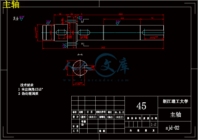
主轴.dwg
从动轴.dwg
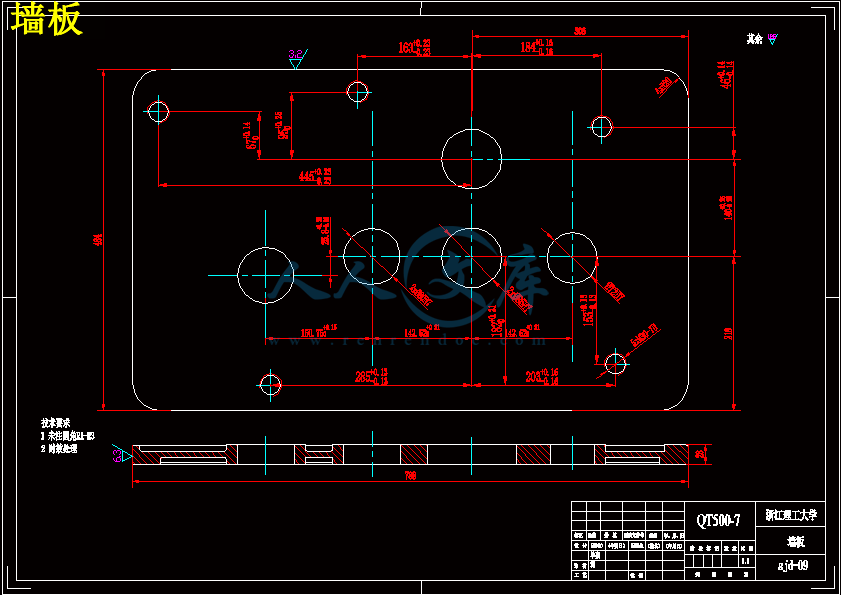
墙板.dwg
挡圈1.dwg
挡圈2.dwg
挡圈3.dwg
摇杆-左.dwg
摇杆.dwg
曲柄.dwg
曲柄座.dwg
椭圆齿轮.dwg
箱体.dwg
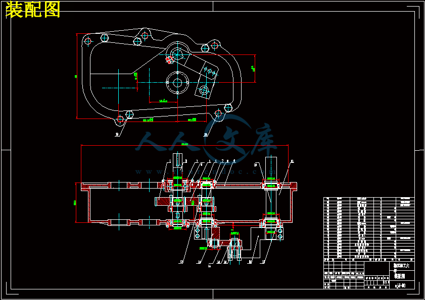
装配图.dwg
输出轴.dwg
连接轴.dwg
连杆.dwg
压缩包内文档预览:
预览图 预览图 预览图 预览图
编号:6040022    类型:共享资源    大小:41.74MB    格式:ZIP    上传时间:2017-10-27 上传人:俊****计 IP属地:江苏
40
积分
关 键 词:
椭圆 齿轮 曲柄 摇杆 打纬 机构 分析 设计 3d-proe 16张 cad 图纸 说明书
资源描述:

摘要

目前在织机中有三种类型:分别是剑杆织机、喷水织机和喷气织机,剑杆织机因结构简单,成本低而应用广泛。我国是一个纺织大国,但由于我国在现代剑杆织机研究不足,当今剑杆织机机构的知识产权不在我国,就不可能将企业做大、做出品牌。要改变中高级剑杆织机生产设备主要依靠进口的局面,必须走自主创新的道路,需要从剑杆织机核心机构开始做基础性研究工作。剑杆织机的打纬机构主要有三种:共轭凸轮机构、四连杆机构和六连杆机构。

本文综述了目前国内外织机发展的现状和打纬机构的研究情况,提出了一种新的打纬机构:椭圆齿轮-曲柄摇杆打纬机构。为分析该机构的打纬性能,建立了机构的运动学数学模型,列出位移、速度和加速度方程。采用Visual Basic 6.0软件编写了辅助分析软件,得到打纬机构的运动学特性曲线。

了解和分析机构参数对运动规律的影响,通过对机构运动目标的确定,来优化打纬机构的各参数,本文采用基于VB6.0编写的可视化软件进行人机交互对话优化方法,结合实际设计时的结构限制,取得了一组最佳参数。

关键字:打纬机构;椭圆齿轮;曲柄摇杆;运动学分析;参数分析


Abstract

At present,there are three types looms,namely the rapier,water and air-jet looms,rapier has broad application because of its simple structure and low cost.China is a big textile country,but because lacking research in modem rapier,rapier in today’s intellectual property is not in our country,which restricted the domestic enterprises become strong and make famous brand,to change the situation that high product equipment of rapier mainly depends on imports,must take the road of independent innovation and should start do basic research from core component of the rapier.Rapier of the beating—up mechanism has three main types:conjugate cam,four-bar linkage and six—bar linkage.

This paper reviewed the current development of looms boom domestic and foreign and also the situation of the beating-up mechanism study,present a new type beating-up mechanism:elliptical gear—crank-rocker beating—up mechanism,and then establish the kinematics mathematical model of beating—up mechanism,and the equation of displacement ,velocity and acceleration will be list,for analysis the performance of beating—up mechanism,kinematics analysis of the new beating-up mechanism was made with Visual Basic 6.0 software,output beating-up mechanism’s kinematics curve.

Understand and analyses the effect of parameters on law of motion, by exterminating the target of mechanism motion, based on the visualization software of VB6.0 for interactive dialogue optimization methods,obtained a set of best Parameters with the structure restrictions while doing actual design.

Key words:beating--up mechanism;elliptic gear;crank-rocker;kinematics analysis;parameter analysis ;


目  录

摘  要

Abstract

第一章 绪论 1

    1.1引言......................................................................................................................................1

    1.2几种典型的打纬机构 2

1.2.1 概述 2

1.2.2 四连杆打纬机构 2

1.2.3 六连杆打纬机构 5

1.2.4 共轭凸轮打纬机构 6

1.3打纬机构国内外研究现状 7

第二章 椭圆齿轮-曲柄摇杆打纬机构运动学建模 8

2.1椭圆齿轮一曲柄摇杆打纬机构简介 8

2.2机构运动学目标 8

2.3椭圆齿轮一曲柄摇杆的打纬机构运动学模型的建立 9

2.3.1从动椭圆齿轮角位移、角速度和角加速度数学模型建立 9

2.3.2摇杆的角位移、角速度和角加速度数学模型建立 11

2.3.3 打纬点的角位移、角速度和角加速度数学模型建立 12

第三章 辅助分析软件的功能及其使用方法 14

3.1 打纬机构运动学辅助分析初始界面 14

    3.2打纬机构运动学辅助分析运行界面 15

3.3 打纬机构运动学辅助分析模拟界面 15

3.4进步界面 16

第四章 机构参数对运动规律的影响 18

4.1 椭圆偏心率k的影响 18

4.2 初始安装角δ的影响 18

4.3 曲柄、连杆长度的影响 19

4.4 摇杆运动性能分析 20

第五章 机构的结构设计 22


5.1 箱体的设计 22

5.1.1 箱体的结构约束 22

5.1.2 新机构参数的选择 23

5.1.3 箱体的结构设计 23

5.2 椭圆齿轮的三维模型建立 24

5.3 曲柄的设计和图纸 25

5.4 摇杆的设计和图纸 26

5.5轴的设计和图纸 27

5.5.1 轴的材料选择 27

5.5.2 轴的结构设计 27

5.5.3提高轴的强度措施 28

5.5.4 轴的强度校核 29

5.6 三维装配图 29

第六章 总结 31

参考文献 32

致  谢 33


第一章 绪论

1.1引言

我国是纺织大国,纺织品的出口量位居世界第一,同时也是纺织机械进口大国,据我国海关统计,2011年1-11月我国纺织机械进出口总额为53.83亿美元,同比增长59.56%。其中进口金额为38.1亿美元,纺织机械出口金额为15.73亿美元[1]。在1:3的纺织机械中,织机位居第二,为5.29亿美元,占18.14%,同比增长17.86%,主要是喷气织机、剑杆织机和片梭织机。2008年上半年我国纺织机械及其零附件出口额8.10亿美元,同比增长6.60%,6月出口额为1.28亿美元。2010年1-11月我国纺织机械进出口额为38.10亿美元,同比增长65.69%。

我国有不少织机生产厂家,但其产品大多是中低档水平,且没有形成世界知名品牌。虽然有一些厂家开始生产高档织机,如中国纺织机械集团有限公司和经纬纺织机械股份有限公司,但其产品在可靠性和耐久性方面却远远不如进口产品,特别是不能长时间高速运转(在演示和展销期间可以高速运转),究其原因, 

除了关键零部件的材质和热处理不过关外,对核心工作部件的工作机理没有进行深入的研究,造成运动构件之间受力不良也主要原因之一。因此虽国内机织在价格上具有优势(如国产剑杆织机价格平均在12万元/台,而2010年进口的剑杆织机平均价格为5.45万美元),但很多企业还是青睐进口产品。

出现这种状况的原因是,国内织机厂家自主创新能力差。到2004年4月,在我国申请有关剑杆织机机构的相关专利共35件,其中国外在华侨申请11件,且这11件已经进入实用和推广。国内企业对核心机构(如打纬和引纬机构)的研究还停留在测绘和仿制阶段,这不仅带来侵权法律问题,不可能将企业做大、做出品牌,同时也由于没有从理论上进行深入研究,对其中的核心技术没有完全掌握,就仿制不了预想的性能和可靠性。可见织机的研究必须走自主创新的道路,必须从核心执行机构创新开始,运用计算机分析软件获得最佳参数,取得自主知识产权,然后再研究其工作机理、优化性能和提高可靠性,才能创自己的品牌和名牌产品。


1.2几种典型的打纬机构

1.2.1 概述

打纬机构是织机的主要机构之一,作用是将织机主轴的匀速旋转运动转化为摇轴的非匀速摆动,把新引入的纬纱推向织口形成织物,要求钢扣在后心位置要有停顿时间或“近似停顿”时间,以便有充分的时间完成打纬运动。

为了实现理想的打纬运动,并使打纬机构符合织造工艺要求,达到最佳经济

效益,对打纬机构的工艺要求如下:


内容简介:
Received date: 2010-01-19Foundation items: National Natural Science Foundation of China ( No 50875243) ; Zhejiang Technique Innovation Group of Modern TextileMachinery, China ( No 2009R50018) ; Foundation of Education Department of Zhejiang Province, China ( No Y201019088) ; Foundation ofNew Textile R D Emphasised Laboratory of Zhejiang Province, China ( No 2009FZD004)* Correspondence should be addressed to CHEN Jian-neng, E-mail: jiannengchen zstu edu cnKinematic Analysis and Test Study of Elliptic-Gear and Crank-Rocker Beating-UpMechanismZHAO Xiong( 赵 雄 ) , REN Gen-yong( 任根勇 ) , CHEN Jian-neng( 陈建能 )*College of Mechanical Engineering and Automation, Zhejiang Sci-Tech University, Hangzhou 310018, ChinaAbstract: In order to analyze the kinematic performances ofelliptic-gear and crank-rocker ( EGCR) beating-up mechanism,kinematic mathematic models of the mechanism were established,and an aided analysis and simulation software were compiled Thissoftware can display the kinematic characteristics and simulationmotion of the mechanism according to different parameters It alsosupplies a platform for human-computer interaction A group ofsatisfactory parameters were selected by the software A test bed ofEGCR beating-up mechanism was developed according to theseparameters The kinematic performances of the mechanism wereverified by high-speed video tape recorderKey words: beating-up mechanism; elliptic-gear; crank-rocker;kinematicsCLC number: TS103 135 Document code: AArticle ID: 1672 -5220( 2011) 02-0222 -04IntroductionBeating-up mechanism is one of the key mechanisms of aloom It beats the weft which is inserted by weft-insertionmechanism to form the fabric Its function is to transform theconstant speed rotation of the looms spindle to the non-constant speed reciprocating swing of the sley In order toallow the weft-insertion mechanism to finish inserting thewefts, the sley of the beating-up mechanism should haveadequate dwell time or relative dwell time in the front positionThe performances of beating-up mechanism determine thefabrics quality, and also decide the quality andcompetitiveness of a loom 1Nowadays, there are three general kinds of beating-upmechanisms: four-bar linkage beating-up mechanism, six-barlinkage beating-up mechanism, and conjugated cam beating-upmechanism Generally, four-bar linkage beating-upmechanism is the simplest mechanism with 65-75 relativedwell time Six-bar linkage beating-up mechanism has about120 relative dwell time It has more hinges which producelarger cumulative errors The dwell time of conjugated cammechanism is 220-240, but the conjugated cam mechanismneeds very high precision machining If there are someprocessing errors it will cause certain vibration 2-4In this paper, a new type of beating-up mechanism basedon elliptic-gear and crank-rocker( EGCR) was produced 5,and its kinematic mathematic models were established A testbed was developed and the kinematic performances of themechanism were verified by high-speed video tape recorder,which demonstrated that this new mechanism could meet therequirements of weft beating-up1 EGCR Beating-Up MechanismFigure 1 shows the EGCR beating-up mechanism in itsinitial position O is one of the focuses of the active elliptic-gear 1 and the rotation centre of the looms spindle A is one ofthe focuses and the rotation centre of the driven elliptic-gear 2Crank AB ( l1) is fixed on the driven elliptic-gear Rocker CD( l3) is driven by BC ( l2) and swings reciprocally Sley DE( l5) is fixed with CD by axis D and swings reciprocallytogether with CD By optimizing the eccentricity k ( the ratioof the elliptic-gears minor radius( b) to major radius( a) ) ,the angle ( the included angle between AD ( l4) and crank ABwhen crank AB and linkage BC are collinear, that is the sleyDE will be in the front position) , ( the included anglebetween the major axis of the active elliptic-gear and AO) , ( the included angle between AD and x-axis) , and the lengthsof linkages in crank-rocker mechanism, the kinematicperformances of this novel beating-up mechanism becomeexcellent, which are similar to those of the conjugated cambeating-up mechanism1Active elliptic-gear; 2Driven elliptic-gear; DESleyFig 1 EGCR beating-up mechanism with its initial position2 Kinematic Mathematic Models ofEGCR Beating-Up Mechanism2 1 Mathematical models of the driven elliptic-gearIn Fig 1, when the active gear 1 rotates anticlockwise at aconstant speed, gear 2 will rotate clockwise at a non-constantspeed Given the angular displacements of the active gear 1 1and driven gear 2 2, the distance from mesh point P to axis Ois r1and PA is r2 With calculation, thenr1= b2/( a + ccos 1) , ( 1)r2= b2/( a + ccos 2) , ( 2)where, c is the distance between the elliptic-gear center and thefocus; 1ranges from 0 to 2, and 2from 0 to 2 6According to the transmission principles of elliptic-gearsr1= 2a r2, ( 3)222 Journal of Donghua University ( Eng Ed ) Vol 28, No 2 ( 2011)that is,cos 2=( a + ccos 1) b2( 2a2+ 2accos 1 b2) cac ( 4)From Eq ( 4) , the relationship between 2and 1can beobtained According to the principles of gear transmission2=1r1r2 ( 5)Given that the velocity of active gear is constant,2= 1r1r2 r1r2r22= 2a r2r221 ( 6)Taking the derivative of Eqs ( 1 ) and ( 3 ) , r1=b2csin 1( a + ccos 1)21and r2= r1, so in Eq ( 6)r2= b2csin 1( a + ccos 1)21 ( 7)2 2 Kinematical models of rocker CDSince the crank is fixed on the driven elliptic-gear, itsangular velocity and angular acceleration are the same as thoseof the driven elliptic-gear That is to say, j1= 2, j1= 2,and j1= + + 2 From Fig 2, the following equations canbe deduced 7Fig 2 Crank-rocker mechanismj2= arctanyC yBxC xB( 8)j4= arctan(yB yDxB xD) ( 9)j3= arccos(l32+ ( xD xB)2+ ( yD yB)2 l222l3( xD xB)2+ ( yD yB)槡2) + j4( 10)j2=VxBcos j3+ VyBsin j3l2sin( j2 j3)( 11)j3=VxBcos j2+ VyBsin j2l3sin( j2 j3)( 12)j2=c1cos j3+ c2sin j3l2sin( j2 j3)( 13)j3=c1cos j2+ c2sin j2l3sin( j2 j3)( 14)In Eqs ( 13) and ( 14) ,c1= axB+ l3j23cos j3 l2j22cos j2, ( 15)c2= ayB+ l3j23sin j3 l2j22sin j2 ( 16)2 3 Kinematic models of E in x-axis direction onthe sley DEDisplacement equation:sxE= xD+ lDEcos( j3 ) ( 17)Velocity equation:VxE= lDEj3cos( j3 /2) ( 18)Acceleration equation:axE= lDEj32cos j3+ lDEj3jcos( j3 /2) ( 19)3 Aided Analysis and SimulationSoftware of Mechanism andParameter Optimization3 1 Aided analytical softwareThe visualization of the mechanism is analyzing andoptimizing process that can display more information of theprocess to users Users can observe the whole process and findout the essential parameters of the mechanism Human-computer interaction analysis and optimization combine thevirtues of both human and computers Humans possess thecapabilities of illegible illation, judgment and innovation,which can help to dispose random events as well Meanwhile,computers are good at accurate calculation and repeative workHuman and computer can fully display their respectiveadvantages in human-computer interaction optimization Thussatisfactory parameters can be easily achieved 8-10Based on the above kinematic models of EGCR beating-upmechanism, an aided analysis and simulation software arecompiled which is shown in Fig 3 It can be used to analyzethe influences of different mechanism parameters and verifywhether there exist interferences among the components of themechanismFig 3 Aided analysis and simulation software of mechanismWith this software, users can input mechanism parameterssuch as a, k, , l1, l2, l3, l4, and rotary speed of the loomsspindle The mechanism motion simulation will be shown onthe left of the interface; the displacement, velocity, andacceleration curves of point E will be shown respectively on theright of the interface; the optimal value of will be shown onthe left-bottom of the interface The displacement curve showsthat dwell time in the rear position decreases as k increases;322Journal of Donghua University ( Eng Ed ) Vol 28, No 2 ( 2011)meanwhile the acceleration curve shows that the maximalacceleration also decreases as k increases For kinematicperformances of the mechanism, k needs to be optimizedaccording to the requirements of the beating-up weft; l1, l2,l3, and l4also need to be modified by the user in company withk, so as to achieve ideal kinematic performances3 2 Optimization results analysisOne of the most important performances of beating-upmechanism is the dwell time of sley Increasing mechanismparameter k can prolong dwell time, meantime the maximalacceleration increases remarkably, and the oversize fluctuationof acceleration will degrade mechanism dynamic performanceDesigner must therefore make a balance between prolongingdwell time and controlling acceleration fluctuationWith the above aided analysis and simulation software, agroup of parameters was obtained: = 4, k = 0 85, =135, a = 71 233 mm, l1= 40 mm, l2= 100 mm, l3= 180mm, l4= 199 mm, and lDE= 189 5 mm Based on theseparameters, when the loom has a speed of 300 r/min, thekinematical curve of the beating point E is shown in Fig 4When the beating-up mechanism is on the rear position, thedisplacement curve is almost flat The dwell time of sley isclose to 200 ( ranging from 92 to 285) , which will not leadto interference of the beating-up mechanism and weft-insertionmechanism In addition, during this period, the curves of thevelocity and acceleration of the sley are almost close to 0Therefore it will not cause vibration, which will benefit thewefts entery and exit from shed At the end of the beating-up,the maximal displacement is 85 mm and the maximalacceleration is 615 843 4 m /s2, which both can meet therequirements of the beating-up weftFig 4 The kinematic curves of EGCR beating-up mechanism4 Test StudyBased on the above parameters, a test bed of EGCRbeating-up mechanism is developed ( Fig 5) Using the high-speed video tape recorder and video analysis software BlastersMAS, the displacement and velocity are obtained with loomspindles rotary speed at 100 r/min Theoretical andexperimental displacements of beating point E are shown inFig 6, and theoretical and experimental velocities of beatingpoint E are shown in Fig 7 The actual measured displacementcurve is consistent with the theoretical one, but the actualmeasured velocity curve shows some fluctuation There aretwo reasons for this finding: the gap among the components ofthe mechanism causes vibration; the video analysis containserrors422 Journal of Donghua University ( Eng Ed ) Vol 28, No 2 ( 2011)5 Conclusions( 1) In this paper, the EGCR beating-up mechanism hadbeen produced Its kinematic mathematic models had beenestablished and an aided analysis and simulation software hadbeen compiled by visual basic A group of satisfactoryparameters had been got by this software( 2) A test bed of the EGCR beating-up mechanism wasdeveloped With the video tape recorder, its kinematicperformances were verified This demonstrated the validity ofthe models and the feasibility of the mechanismReferences 1 Zhu S K, Gao W D Weaving Machine M 2nd ed Beijing:China Textile Apparel Press, 2004: 267-268 ( in Chinese) 2 Liang H S, Hu Q E, Wang G C, et al The Fuzzy OptimizationDesign of the Four-Link Weft Beat-Up Mechanism J Machine Design and Research, 2005, 21 ( 2 ) : 72-75 ( inChinese) 3 Ma S P Optimal Design and Simulation on 6-Link BeatingConstru
温馨提示:
1: 本站所有资源如无特殊说明,都需要本地电脑安装OFFICE2007和PDF阅读器。图纸软件为CAD,CAXA,PROE,UG,SolidWorks等.压缩文件请下载最新的WinRAR软件解压。
2: 本站的文档不包含任何第三方提供的附件图纸等,如果需要附件,请联系上传者。文件的所有权益归上传用户所有。
3.本站RAR压缩包中若带图纸,网页内容里面会有图纸预览,若没有图纸预览就没有图纸。
4. 未经权益所有人同意不得将文件中的内容挪作商业或盈利用途。
5. 人人文库网仅提供信息存储空间,仅对用户上传内容的表现方式做保护处理,对用户上传分享的文档内容本身不做任何修改或编辑,并不能对任何下载内容负责。
6. 下载文件中如有侵权或不适当内容,请与我们联系,我们立即纠正。
7. 本站不保证下载资源的准确性、安全性和完整性, 同时也不承担用户因使用这些下载资源对自己和他人造成任何形式的伤害或损失。
提示  人人文库网所有资源均是用户自行上传分享,仅供网友学习交流,未经上传用户书面授权,请勿作他用。
关于本文
本文标题:椭圆齿轮-曲柄摇杆打纬机构的分析与设计【3D-PROE】【16张CAD图纸和说明书】
链接地址:https://www.renrendoc.com/p-6040022.html

官方联系方式

2:不支持迅雷下载,请使用浏览器下载   
3:不支持QQ浏览器下载,请用其他浏览器   
4:下载后的文档和图纸-无水印   
5:文档经过压缩,下载后原文更清晰   
关于我们 - 网站声明 - 网站地图 - 资源地图 - 友情链接 - 网站客服 - 联系我们

网站客服QQ:2881952447     

copyright@ 2020-2025  renrendoc.com 人人文库版权所有   联系电话:400-852-1180

备案号:蜀ICP备2022000484号-2       经营许可证: 川B2-20220663       公网安备川公网安备: 51019002004831号

本站为文档C2C交易模式,即用户上传的文档直接被用户下载,本站只是中间服务平台,本站所有文档下载所得的收益归上传人(含作者)所有。人人文库网仅提供信息存储空间,仅对用户上传内容的表现方式做保护处理,对上载内容本身不做任何修改或编辑。若文档所含内容侵犯了您的版权或隐私,请立即通知人人文库网,我们立即给予删除!