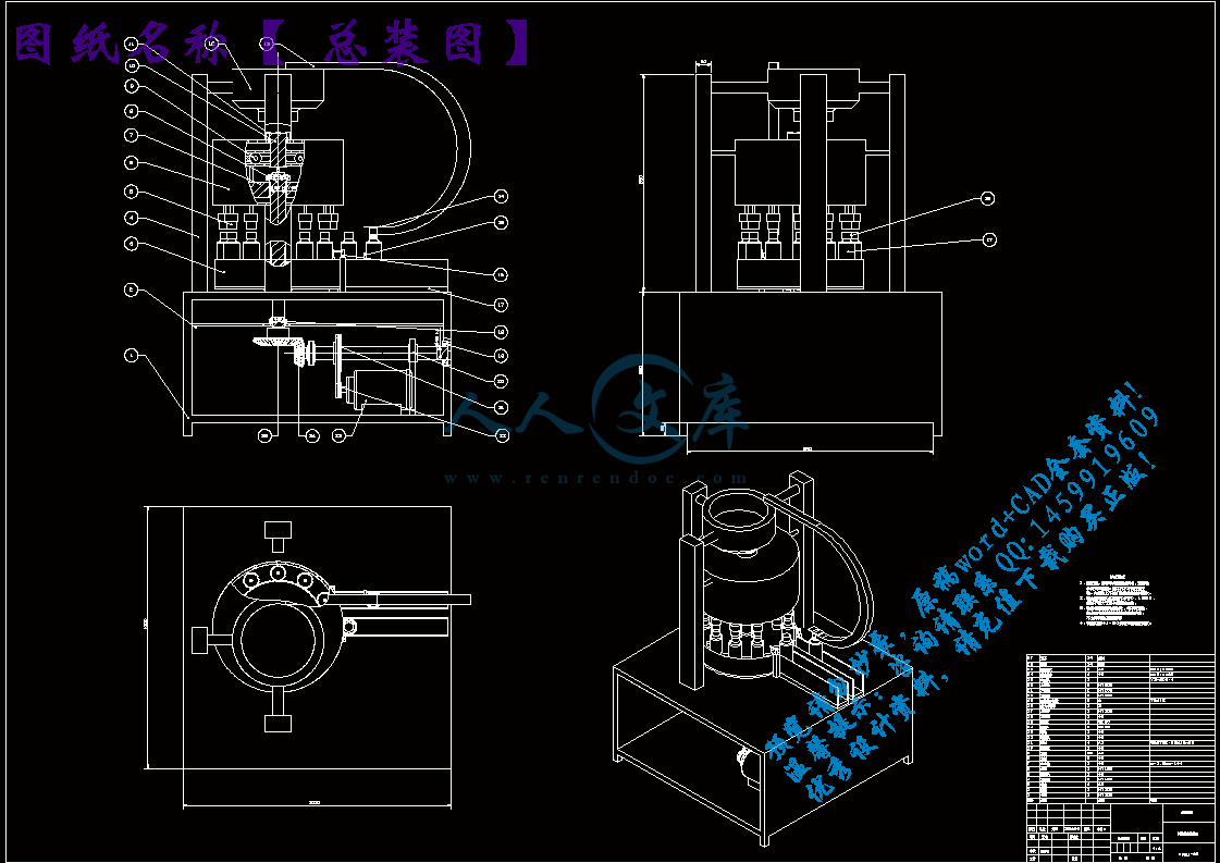
转盘.dwg
转盘.dwg

液体灌装生产线上拧瓶盖机的设计【优秀】【带UG三维】【word+9张CAD图纸】【毕设】

收藏

资源目录
跳过导航链接。
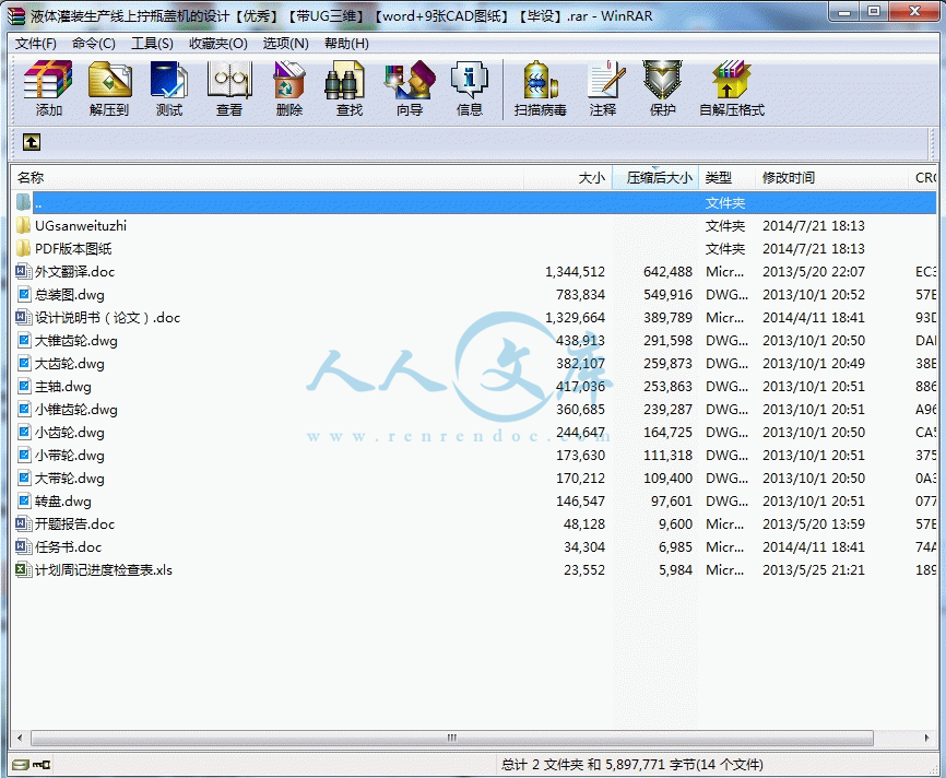
液体灌装生产线上拧瓶盖机的设计【优秀】【带UG三维】【word+9张CAD图纸】【毕设】.rar
转盘.dwg---(点击预览)
设计说明书(论文).doc---(点击预览)
计划周记进度检查表.xls---(点击预览)
总装图.dwg---(点击预览)
开题报告.doc---(点击预览)
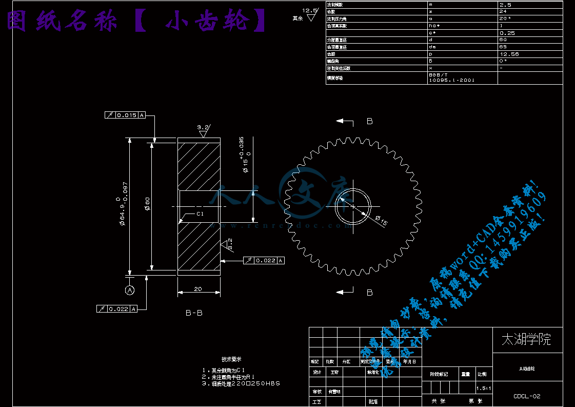
小齿轮.dwg---(点击预览)
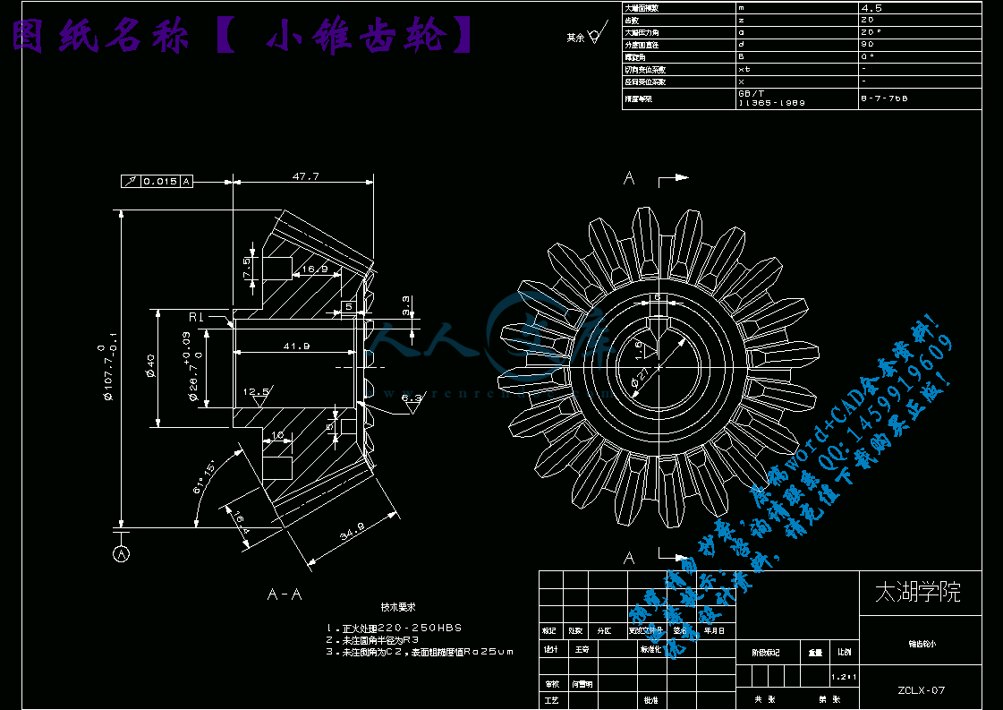
小锥齿轮.dwg---(点击预览)
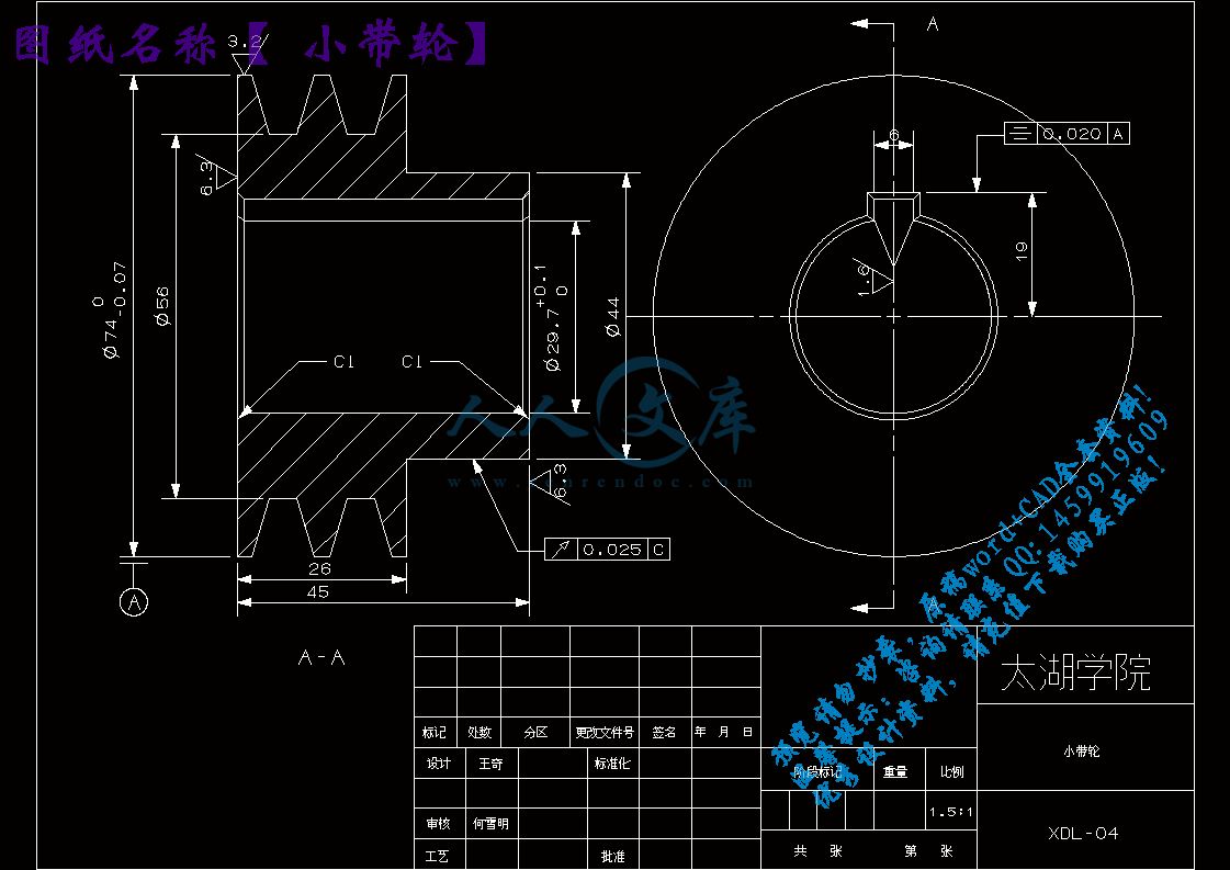
小带轮.dwg---(点击预览)
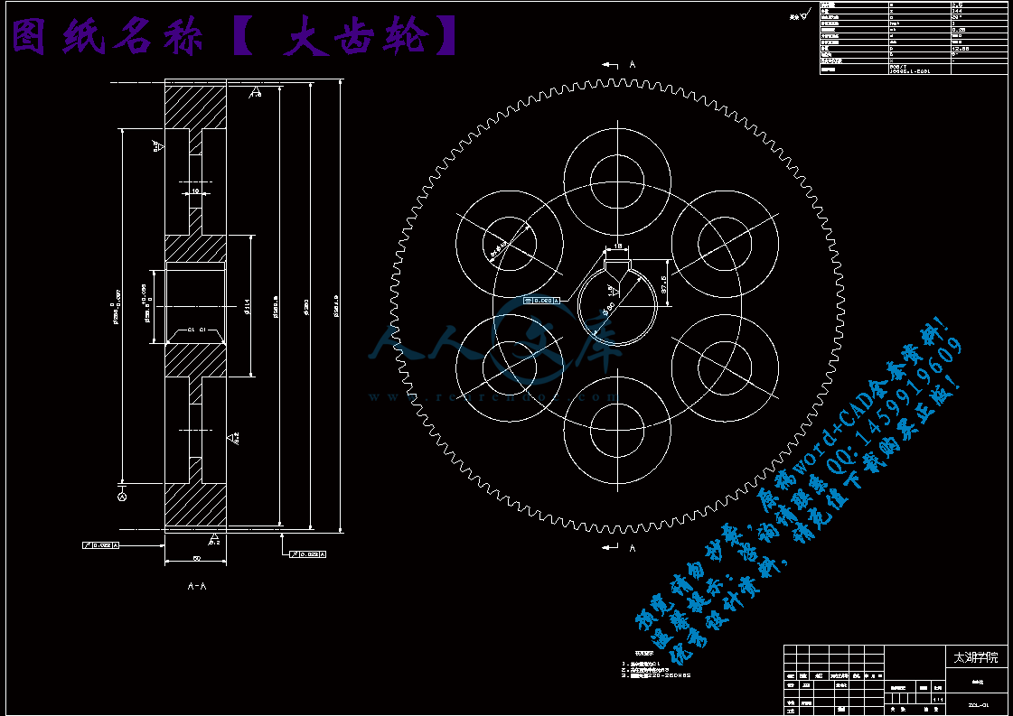
大齿轮.dwg---(点击预览)
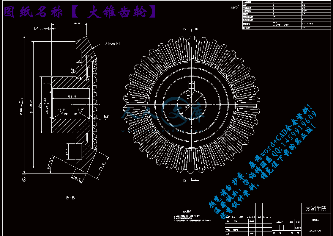
大锥齿轮.dwg---(点击预览)
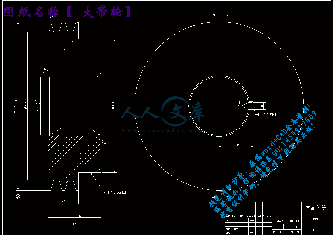
大带轮.dwg---(点击预览)
外文翻译.doc---(点击预览)
任务书.doc---(点击预览)
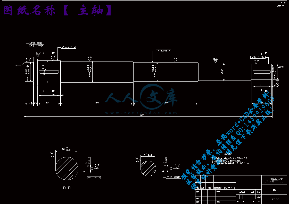
主轴.dwg---(点击预览)
PDF版本图纸
UGsanweituzhi
13 m10 luoshuan 3.prt
a1.prt
A11.prt
A12.prt
a2.prt
a3.prt
a4.prt
a5.prt
a7.prt
a8.prt
a9.prt
chilun2.prt
chilunda360.prt
chilunxiao60.prt
chulun11.prt
dailunda140.prt
dailunxiao70.prt
dangban1.prt
dangban2.prt
dangban3.prt
dangban5.prt
dangban7.prt
dangban8.prt
dangban9.prt
dianji.prt
dianji1.prt
dianji2.prt
dianji3.prt
dianji4.prt
dianji5.prt
dianji7.prt
dianji9.prt
jian47.prt
jian52.prt
ligaiji1.prt
ligaiji2.prt
ligaiji3.prt
ligaiji4.prt
ligaiji5.prt
ligaiji6.prt
ligaiji7.prt
pinggai.prt
pingzi.prt
shengjiang1.prt
shengjiang10.prt
shengjiang11.prt
shengjiang3.prt
shengjiang4.prt
shengjiang5.prt
shengjiang6.prt
shengjiang7.prt
shengjiang8.prt
shengjiang9.prt
xiangzuo.prt
xiangzuo1.prt
xiechilun.prt
xiechilun1.prt
xiechilun2.prt
yuanzhuzhoucheng1.prt
yuanzhuzhoucheng2.prt
zhicheng1.prt
zhoucheng xiao.prt
zhoucheng.prt
zhoucheng1.prt
zhoucheng2.prt
zhoucheng3.prt
zhoucheng4.prt
zhuangpan4.prt
zhuangpan5.prt
zhuanpan1.prt
zhuanpan2.prt
zhuanpan3.prt
zhuichilunda.prt
zhuichilunxiao.prt
zhuzhou.prt
zhuzhoutuzhi.prt
压缩包内文档预览:
预览图
编号:315973    类型:共享资源    大小:10.64MB    格式:RAR    上传时间:2014-08-21 上传人:QQ14****9609 IP属地:陕西
50
积分
关 键 词:
液体灌装 生产线 拧瓶盖机 拧盖机 设计 优秀 优良 ug 三维 word cad 图纸
资源描述:

液体灌装生产线上拧瓶盖机的设计【优秀】【带UG三维】【word+9张CAD图纸】【毕业设计】

【带任务书+开题报告++外文翻译】【35页@正文13500字】【详情如下】【需要咨询购买全套设计请加QQ1459919609】.bat

PDF版本图纸

UGsanweituzhi

主轴.dwg

任务书.doc

外文翻译.doc

大带轮.dwg

大锥齿轮.dwg

大齿轮.dwg

小带轮.dwg

小锥齿轮.dwg

小齿轮.dwg

开题报告.doc

总装图.dwg

计划周记进度检查表.xls

设计说明书(论文).doc

转盘.dwg

题目:  液体灌装生产线上拧瓶盖机的设计

毕 业 设 计论 文 任 务 书

一、题目及专题:

1、题目  液体灌装生产线上拧瓶盖机的设计              

2、专题                                                

二、课题来源及选题依据

   拧盖机是自动灌装生产线的主要设备之一,用于玻璃瓶或PET瓶的螺纹盖封口。随着社会的发展和人民生活水平的提高,人们对产品的包装质量的要求也越来越高。由于螺纹盖具有封口快捷,开启方便及开启瓶后又可重新封好等优点,使其在许多产品的包装中应用越来越广泛,诸如饮料,酒类,调味料,化妆品及药品等瓶包装的封口就大量采用螺纹盖封口。目前现有的国产同类机型的封盖机的产量,速度和自动化程度都相对落后。为了适应现代包装机高速,高效和高可靠性生产的需要,研制了一种回转式拧盖机,该机采用多工位回转式结构,机电气一体化,具有效率高,速度快,可靠性好和自动化程度高等优点。本次设计介绍了液体灌装生产线上拧瓶盖机。    

三、本设计(论文或其他)应达到的要求:

① 阅读外文资料,翻译与本专业或课题相关的外文文献3000字左右,要求语句通顺、流畅、准确;                                            

② 了解拧瓶盖的工作原理;                                        

③ 通过对比现有的拧瓶盖机,初步拟定分析设备方案;                                        

④ 绘制部分零件图,装配图,零件的各种配合;                                      

⑤ 能够熟练使用UG,用UG对部分零件进行建模;                    

⑥ 撰写论文,要求符合本科论文的格式要求,语言简洁、流畅、层次分明。上机时数不少于200小时,整个毕业设计过程的技术工作要 严谨、灵活、工作要有主动性,计算方法、计算的程序、计算结果、 结论要正确。                                                                                        

摘要

回转式拧瓶盖机适用于带螺纹的盖与瓶的旋盖,市场上现有的回转式拧瓶盖机大多数是半自动的包装机,瓶盖的疏理大多由人工来完成,生产效率不是很高,而且加大了劳动的强度,再生产时有一定的危险,本设计为自动理盖而且是多工位拧盖机。

本文介绍了题目的研究背景和意义,论述了拧盖机在国内外的发展状况,介绍了本次设计研究的内容及方法。本次设计的重点是拧盖机的总体设计方案、过程的拧盖、输送方式和定位方法,在此基础上进行了运动与结构的设计。本次设计采用的拧盖方法是回转式的,是通过圆柱凸轮的轮廓线来实现拧盖头的上下往复运动的,通过锥齿轮传递转矩;而且在满足拧盖机原理的条件下,充分考虑了整机的布局和经济性,不但结构简单明了,操作方便而且本课题的设计实现了从进瓶到出瓶的全部自动化,具有速度可调、定位准确、旋盖可靠、运行平稳、无噪音和不伤瓶盖等优点,克服了传统机构的缺点,总体上达到了我们预期设计的目标。

关键词:拧瓶盖机构;理盖机构;传送;自动化;转盘

Abstract

Rotary Capping Machine for the threaded cap and the bottle of screw cap, as the existing rotary capping machines are mostly semi-automatic packaging machine, bottle of Reorganizing the employer to complete most of the production efficiency is not very high and increased labor intensity, have a certain risk of reproduction, the design for the automatic management is a multi-position cap and screw cap.

   This article describes the background and significance of the research topics discussed. Capper development at home and abroad, introduces the design of this study the content and methods. The packaging machine is designed to focus the overall design scheme, the packaging process of screwing conveyance methods and positioning methods, in this based on the movement and structure design. The design of the packaging used is rotary,through cylindrical cam contour to achieve capping head up and down reciprocating motion through the planetary gear transmission torque; and packaging machinery to meet the conditions of principle, give full consideration to the machine layout and the economy, while machine is also simple, low cost, no pollution, noise and human and functional characteristics of reasonable.

Keywords: Cappjing Machine;cancelling machine;deliver;automation;turntabl

目录

摘要III

AbstractIV

1 绪论1

1.1 本课题的研究内容和意义1

1.2 国内外的发展概况1

1.3 本课题应达到的要求1

2 总体方案设计2

2.1 方案一的介绍2

2.2 方案二的介绍2

2.3 方案比较2

2.4 采用方案的详细设计3

2.4.1 上盖装置的设计3

2.4.2 传送带的设计4

2.4.3 底座箱的设计4

2.4.4 拧盖机构的设计4

2.4.5 转盘的设计5

3 总装图的确定6

3.1 主要技术参数的确定6

3.1.1 电机的选择6

3.2 传动方案的确定7

3.3 结构方案的确定7

4 部件装配图的确定9

4.1 带传动的计算9

4.2 轴的设计计算和校核11

4.2.1 轴的结构设计及选材11

4.2.2 轴的设计计算11

4.2.3 轴的校核计算12

4.3 齿轮的计算和校核12

4.3.1 齿轮材料处理工艺及制造工艺的选定12

4.3.2 确定各主要参数13

4.3.3 传动比13

4.3.4 齿轮模数m13

4.3.5 齿轮接触疲劳强度计算13

4.3.6 齿轮强度校核14

4.4 锥齿轮的计算和校核19

4.4.1 选取齿轮类型,精度等级,材料及齿数19

4.4.2 按齿面接触强度设计19

4.4.3 设计计算19

4.4.4 按齿根弯曲强度设计20

4.4.5 设计计算21

4.4.6 几何尺寸计算22

4.5 键的计算和校核23

4.5.1 键的选择计算23

4.5.2 键的校核23

4.6 轴承的选择和校核23

4.6.1 轴承的选择23

4.6.2 轴承的寿命计算24

5 拧盖机的工作情况简介26

5.1 传送及拧盖部分26

5.2 控制部分26

6 拧盖机的安装、维护和安全28

6.1 安装28

6.2 维护保养28

6.3安全要求28

7 结论与展望29

7.1 结论29

7.2 不足之处及未来展望29

致 谢30

参 考 文 献31

1 绪论

1.1 本课题的研究内容和意义

拧盖机是自动灌装生产线的主要设备之一,用于玻璃瓶或PET瓶的螺纹盖封口。随着社会的发展和人民生活水平的提高,人们对产品的包装质量的要求也越来越高。由于螺纹盖具有封口快捷,开启方便及开启瓶后又可重新封好等优点,使其在许多产品的包装中应用越来越广泛,诸如饮料,酒类,调味料,化妆品及药品等瓶包装的封口就大量采用螺纹盖封口。目前现有的国产同类机型的封盖机的产量,速度和自动化程度都相对落后。为了适应现代包装机高速,高效和高可靠性生产的需要,研制了一种回转式拧盖机,该机采用多工位回转式结构,机电气一体化,具有效率高,速度快,可靠性好和自动化程度高等优点。

包装机械为包装工业提供装备机械,影响着各类包装制品工业的技术水平和产品档次,制约着包装工业的发展和速度。长期以来,我国包装机械行业非常薄弱,形不成规模和水平,致使我国包装工业发展极慢。我国包装机械行业在历经了七十年代的起步,八十年代的发展,九十年代由于包装制品发展的需要而实现了高速度发展,但是由于起步迟,起点低,规模小,我国包装机械总体水平要比发达国家落后20年,国内目前需求量的60%,尤其是技术含量高的技术装备依赖进口。对于包装制品工业,包装机械是我国包装工业的优势。

1.2 国内外的发展概况

提高自动化程度是包装机械发展重要的趋势。产品和产量居世界之首的美国十分重视白装机械与计算机紧密结合,实现机电一体化控制,将自动化操作程序、数据收集系统、自动检验系统更多用于包装机械之中。日本则长于微电子技术,用以开那个值包装机械,有效地促进了无人操作和自动化程度的提高。在计量、制造和技术性能等方面居于世界领先地位的德国也高度重视提高自动化程度。几年前,德国包装机械系统设计时,自动化技术在整个系统操作及运行中还占30%,现在已占到50%以上。

1.3 本课题应达到的要求

目前国内液体灌装生产线中广泛使用的旋开封盖口机大多为直线式拧盖机,为了适应现代包装机高速、高效和高可靠性生产的需要,在广泛吸收国内外先进机型的基础上,设计此了机器。该拧瓶盖机采用回转式结构。本次设计是针对回转式拧盖机整体的设计。主要工艺流程包括:供瓶+供盖—旋盖—输送。同时要求熟练的操作UG软件,进行建模,绘制图3D模型并出图纸。

2 总体方案设计

2.1 方案一的介绍

如图2.1所示,该方案利用步进电机带动传送带将待旋盖瓶传送至上盖装置下方自动上盖并抚平,然后将上好盖的瓶子停止在旋盖机正下方,传感装置将信号传至旋盖机构,通过上部的气缸实现旋盖头的整体下移,通过下部的杠杆机构实现瓶子的夹紧,选盖头旋转将瓶盖旋紧在瓶上。旋盖完成后旋盖头升起,传送带继续前进一定距离,开始重复旋盖过程。本方案结构较为简单、易懂,但是从整体来分析,旋盖的效率不是太高,而且对传送带的各种要求比较高,需要特别订制,成本会提高。


图2.1 方案一旋盖机的结构的正视图

2.2 方案二的介绍

如图2.3所示,本方案的全自动旋盖机由上盖装置,传送带,底座箱,拧盖机构,旋瓶圆盘,电机等组成。瓶子靠传送带一直匀速的前进,通过理盖机振动供盖,然后进入旋盘,一直旋转的旋盖头靠升降机构的作用整个支撑杆向下运动完成旋盖并抬起,与此同时,前面旋盖完成的瓶子会随着传动带输出。从而,顺利的完成了全自动旋盖的整个过程。这样既能达到高效迅速旋盖的目的,同样在一定范围内也能适用于不同高度大小的瓶子旋盖。

2.3 方案比较

方案一结构简单,生产成本低,但是传送带的停走精度难以控制,所以整个旋盖的精度低而且生产效率低,而且整个装置的自动化程度不是很高,较为适合小批量生产;方案二结构设计简单且精密合理,旋盖精度高,效率高,相对于方案一成本要高,但是自动化程度也较高,适合批量生产,综合考虑多方面,本课题采用方案二的结构进行设计。

参 考 文 献

[1] 张伟安.全自动回转式旋盖机[M].轻工机械,2002,第二期:42-43.

[2] 王旭,王积森.机械设计课程设计[M].机械工业出版社,2003.

[3] 梅顺齐,杜雄星.旋盖机磁力旋盖头的分析与设计[M].磁性材料及器件:32-34.

[4] 李诗龙.FX12型旋盖机的设计[M].包装机械,2000,第三期:24-26.

[5] 孙秀延,赵大民,王秀伦.XG12全自动回转式旋盖机的设计[N].沈阳工学院报,第四卷第一期:82-83.

[6] 刘基农.运用价值分析设计高速全自动旋盖机.咨询服务,第一期:30-34.

[7] 刘基农.高速全自动旋盖机[P].中国专利:881056758,1989-09-06.

[8] 朱建兵.全自动旋盖机[P].中国专利:2009200366972,2010-1-13.

[9] 郭清富,刘春华,郭明哲等.自动旋盖机[P].中国专利:962239305,1998-03-11.

[10] 叶益芳.自动封盖机[P].中国专利,94216658.2.1995-06-07.

[11] 刘世刚.万能旋盖机[P].专利检索,CH2425855Y.

[12] 李诗龙.高速旋盖机传动系统的设计[M].轻工机械,1999,第四期:27-30.

[13] 濮良贵,纪名刚.机械设计(第八版)[M].北京:高等教育出版社,2006.

[14] 孙桓,陈作模,葛文杰.机械原理(第七版)[M].北京:高等教育出版社,2006.

[15] 刘美玲,雷振德.机械设计基础[M].北京:科学出版社,2005.

[16] 李业农.机械制图(第四版)[M].上海交通大学出版社,2008.

[17] 韩进宏.互换性与技术测量[M].机械工业出版社,2004.

[18] 康鹏工作室.UG NX4 产品建模实例教程[M].清华大学出版社,2006.

[19] 徐灏.机械设计手册[M].北京:高等教育出版社,1991.

[20] 成大先.机械设计图册[M].第Ⅰ卷.北京:化学工业出版社,2000.

内容简介:
编号无锡太湖学院毕业设计(论文)题目: 液体灌装生产线上拧瓶盖机的设计 信机 系 机械工程及自动化 专业学 号: 0923837学生姓名: 王 奇 指导教师: 何雪明(职称:副教授 ) (职称: )2013年5月25日3无锡太湖学院本科毕业设计(论文)诚 信 承 诺 书本人郑重声明:所呈交的毕业设计(论文) 液体灌装生产线上拧瓶盖机的设计 是本人在导师的指导下独立进行研究所取得的成果,其内容除了在毕业设计(论文)中特别加以标注引用,表示致谢的内容外,本毕业设计(论文)不包含任何其他个人、集体已发表或撰写的成果作品。 班 级: 机械97 学 号: 0923837 作者姓名: 2013 年 5 月 25 日无锡太湖学院信 机系 机械工程及自动化 专业毕 业 设 计论 文 任 务 书一、题目及专题:1、题目液体灌装生产线上拧瓶盖机的设计 2、专题 二、课题来源及选题依据 拧盖机是自动灌装生产线的主要设备之一,用于玻璃瓶或PET瓶的螺纹盖封口。随着社会的发展和人民生活水平的提高,人们对产品的包装质量的要求也越来越高。由于螺纹盖具有封口快捷,开启方便及开启瓶后又可重新封好等优点,使其在许多产品的包装中应用越来越广泛,诸如饮料,酒类,调味料,化妆品及药品等瓶包装的封口就大量采用螺纹盖封口。目前现有的国产同类机型的封盖机的产量,速度和自动化程度都相对落后。为了适应现代包装机高速,高效和高可靠性生产的需要,研制了一种回转式拧盖机,该机采用多工位回转式结构,机电气一体化,具有效率高,速度快,可靠性好和自动化程度高等优点。本次设计介绍了液体灌装生产线上拧瓶盖机。 三、本设计(论文或其他)应达到的要求: 阅读外文资料,翻译与本专业或课题相关的外文文献3000字左右,要求语句通顺、流畅、准确; 了解拧瓶盖的工作原理; 通过对比现有的拧瓶盖机,初步拟定分析设备方案; 绘制部分零件图,装配图,零件的各种配合; 能够熟练使用UG,用UG对部分零件进行建模; 撰写论文,要求符合本科论文的格式要求,语言简洁、流畅、层次分明。上机时数不少于200小时,整个毕业设计过程的技术工作要 严谨、灵活、工作要有主动性,计算方法、计算的程序、计算结果、 结论要正确。 四、接受任务学生:机械97 班 姓名 王 奇 五、开始及完成日期:自2012年11月12日 至2013年5月25日六、设计(论文)指导(或顾问):指导教师签名 签名 签名教研室主任学科组组长研究所所长签名 系主任 签名2012年11月12日英文原文Screw Compressors2.4 Review of Most Popular Rotor Profiles2.3 Rotor Profile CalculationFor a further analysis of the compressor geometry, several generic definitions are introduced here. The rotor gear ratio ,whereandare the numbers of lobes on the main and gate rotor. Since the screw compressor rotors are three-dimensional bodies, a helix angleis defined at the rotor radius, whilecorresponds to the pitch circle,. The helix angle defines the rotor lead h, which can be given relative to the unit angle. The rotor length L, the wrap angleand the lead are interrelated. If the rotors are unwrapped, a simple relation between the wrap and helix angles can be established,. The lead angle is the complement of the helix angle. As shown in Fig. 2.3, the rotor displacement is the product of the rotor length and its cross section area, which is denoted by the number 1, while the overlapping areas on the main and gate rotors are denoted by the number 2.2.4 Review of Most Popular Rotor ProfilesThis section reviews a procedure to calculate various screw profiles. Initially a detailed presentation of rotor creation by the rotor generation procedure is given. The rotor profile in this case is a very simple hypothetical one. It has been applied in practice, but also been frequently used for training purposes. Furthermore, this profile may be very conveniently used as a basis for individual development of screw compressor rotors and such use is encouraged here. Based on this, other profiles are briefly derived, like the early SKBK profile, the “Sigma” profile by Kaeser, the “Hyper” profile by Hanbel and the Fu Sheng and Hitachi profiles. Also the symmetric profile and asymmetricFig. 2.3. Rotor cross section area and overlapping sectors2 Screw Compressor Geometry“A”, “D” and “G” profiles of SRM and the “Cyclon” profile by Compair are reviewed. Finally, two rack generated profiles are described namely the “N” and Rinders profile.2.4.1 Demonstrator Rotor Profile (“N” Rotor Generated)The demonstrator profile is a rotor generated “N” profile and is not to be confused with the patented rack generated “N” profile. The primary or generating lobe profile of the Demonstrator is given on the main rotor and the profile is divided into several segments. The division between the profile segments is denoted by capital letters and each segment is defined separately by its characteristic angles, as shown in the Fig. 2.4. The lobe segments of this profile are essentially parts of circles on one rotor and curves corresponding to the circles on the opposite rotor. A graphical presentation of this profile is presented in Fig. 2.5. The following summarizes the specific expressions for the x-y coordinates of the lobe profiles of the main screw rotor, with respect to the centre of the rotor. Givenare the pitch radii,andand the rotor radii r, ,and. The external and internal radii are calculated asand,as well asandfor the main and gate rotor respectively.In the demonstrator profile, segment A1B1 is a circle of radius on the main rotor. The angular parameter t varies between.Fig. 2.4. Demonstrator Profile2.4 Review of Most Popular Rotor ProfilesFig. 2.5. Details of the Demonstrator Profileis given, while and are calculated through the following procedure, which is presented graphically in Fig. 2.5. There the flat side of the profile is presented in the position where points F1 and F2 coincide:Afterandare obtained from these equations,andcan be calculated as:The other angles are:and. On the round side of the rotors, whereis the number of lobes in the main rotor. The radiusis now calculated from:Other necessary angles are calculated as follows:The segment B1C1 is on a circle of radius on the main rotor, where.2 Screw Compressor GeometryProfile portion A1D1 is a circle of radiuson the main rotor,.Segment C1D1 emerges as a trochoid on the main rotor generated by the circle of radius. The trochoid is obtained from the gate rotor coordinates through the same meshing procedure. The circle C2D2 is:Now, when all the segments of the main rotor are known, they are used as source curves. The gate rotor lobe can now be generated completely by the meshing procedure described in the previous section.Although essentially simple, the Demonstrator profile contains all the features which characterize modern screw rotor profiles. The pressure angles on both, the flat and the round profile lobes are not zero. This is essential for successful manufacturing. The profile is generated by the curves and not by points. This further enhances its manufacturability. By changing its parameters,C, r,and, a variety of profiles can be generated, some with positive gate rotor torque, some suitable for low pressure ratios, and others for high pressure ratio compression. The profile is fully computerized and can be used for demonstration, teaching and development purposes.2.4.2 SKBK ProfileAmosovs 1977 SKBK profile is the first modern Russian profile to be published in the open literature and it is shown in Fig. 2.6. The profile has the same layout and sequence of segments as the Demonstrator profile apart from the fact that the circlesandthe substituted by cycloids and the segments AB and AF are generated by point generation. This can be readily achieved if andin the Demonstrator profile tend to zero.Similarly to the Demonstrator profile, SKBK profile has an eccentric circle on the round lobe of the main rotor, which gives a pressure angle far different from zero in the pitch circle area. This further ensures both its ease of manufacture and the gate rotor torque stability. This characteristic of the SKBK profile was published at least five years prior the SRM “D” rotor patents which claimed the same feature. However, since the flat lobe sides on the main and gate rotors are generated by points E and A on the gate and main rotor respectively and since E is positioned on the gate rotor pitch circle, the pressure angle at the pitch circle on the flat side is zero. This does not allow manufacturing of this profile by milling or grinding unless the profile is modified.2.4 Review of Most Popular Rotor ProfilesFig. 2.6. SKBK ProfileFig. 2.7. Fu Sheng Profile2.4.3 Fu Sheng ProfileThe Fu Sheng profile, as shown in Fig. 2.7, is practically the same as the Demonstrator, but has one distinguishing feature. The segment AB is an ellipse.2.4.4 “Hyper” ProfileThe “Hyper” profile is virtually the same as the Fu Sheng profile, apart from the segment AB, which is a hyperbola on the main rotor instead of the ellipse of the original Fu Sheng profile. However, despite such a small difference, the “Hyper” is a better profile giving larger screw compressor displacement, a shorter sealing line and stronger gate rotor lobes. The Hitachi profile has the same layout as the “Hyper” profile.2 Screw Compressor Geometry2.4.5 “Sigma” ProfileThe “Sigma” is a relatively old profile. It was developed in the late nineteen seventies as a response to SRM awarding an exclusive licence to Aerzener in Germany. Other German manufacturers, such as GHH and Kaeser, therefore, needed to develop their own profiles. The “Sigma”, shown in Fig. 2.8 is a beautiful and efficient profile. However, new and better profiles are now available. The flat side of the “Sigma” lobe is the same as that of the Demonstrator profile, but the round side of the profile is generated from the flat side by an envelope of circles, which touch both the flat and the round sides, the radii of which are given in advance. This is an acceptable method of profile generation if nothing more general is known, but seriously limits the generation procedure. There are several modifications of the “Sigma” profile. One of these, which is presented here, comprises a straight line BC2 on the round side of the gate rotor. This modification significantly improves the profile, which is less limited than the original.Fig. 2.8. Sigma Profile2.4.6 “Cyclon” ProfileThe “Cyclon” shown in Fig. 2.9 is a profile developed by Compair. The layout and sequence of profile segments are not so different from the Demonstrator, but the “Cyclon” introduces parabolae instead of circles in segments BC, GH and JH. One of the interesting features of the “Cyclon” profile is the “negative” torque on the gate rotor which results in rotor contact on the flat side of the rotors.2.4 Review of Most Popular Rotor ProfilesFig. 2.9. Cyclon Profile2.4.7 Symmetric ProfileThe Symmetric profile, shown in Fig. 2.10 is very simple and consists of three circles on the main rotor with centres positioned either on the rotor centre or on the pitch circle of the main rotor. Since the circles are on the main rotor with centres either at the rotor centre or on the pitch circle, they only generate circles on the gate rotor with centres either in the rotor centre, or on the rotor pitch circle. Is is therefore not surprising that this was the first screw rotor profile ever generated.Segment D1E1 is a circle of radiuswith its centre on the rotor axis, while segment E1F1 is a circle of radius r0. Segment F1A1 is on a circle of radius r. Both, the last two segments have their centres on the rotor pitch circle. Further segments are symmetrically similar to the given ones.Fig. 2.10. Symmetric Circular Profile中文译文螺杆式压缩机2.4审查最流行的转子型线2.3转子型线的计算为了进一步分析的压缩机的几何形状,几个通用的定义这里介绍的。转子的传动比为,其中和为数字上的主,闸转子的裂片。由于螺杆压缩机转子三维机构的螺旋角被限定在转子的半径,而对应的节圆,。螺旋线角度定义转子引线h,这可以给定的相对的单位角度。在转子的长度L,包角和引线是相互关联的。如果转子被解开,一个简单的包之间的关系和螺旋角可以建立,。导程角为螺旋角的补。如图中所示2.3,转子的位移是所述转子的产品长度和其横截面面积,这是由数字1表示,而重叠区域上的主转子和闸转子的由数字2表示。2.4审查最流行的转子型线本节审查程序,计算各种规格型材。最初转子由转子产生过程的创建是一个详细的介绍给定的。在这种情况下,转子型线是一个非常简单的假设性。它有在实践中得到了应用,但也经常被用于训练目的。此外,此配置文件可以很方便地使用个人的基础螺杆压缩机转子的发展,这种鼓励在这里。在此基础上,其他的配置文件简单地得出, 像早期SKBK中的个人主页上,由凯撒“西格玛”配置文件,“超”配置文件Hanbel和傅盛和日立的配置文件。此外,对称的轮廓不对称。图.2.3.转子的横截面面积和重叠的扇区2螺杆式压缩几何“A”,“D”,“G”配置文件SRM的“CYCLON”配置文件康普艾综述。最后,即两个机架生成的配置文件中描述的“N”Rinder的个人资料。2.4.1演示转子型线(“N”转子生成)示威者个人资料的转子产生的“ N”配置文件,是不是要拥有专利的机架产生的“N”配置文件相混淆。的主要或生成叶的主旋翼和配置文件的演示中,分成若干段。该部门的档案分部之间用大写字母表示,每个段分别定义其特性的角度,如在图中所示。 2.4。叶段,这配置文件本质上是一个转子的圆形和曲线对应的相反的转子上的圆圈。在此档案中呈现的图形化表示。2.5下面总结的具体表达式的xy坐标的波瓣的公司的的主螺杆转子,相对于转子的中心。特定的间距半径,和和转子的半径r,,和的。“和的内部和外部半径的计算公式为,以及和中的主要和闸转子分别。在示威者配置文件中,段A1B1是一个圆的半径主旋翼。的角度参数t的变化之间的时。图.2.4.演示简介2.4审查最流行的转子型线图.2.5.详细的演示简介给出,而和是通过以下步骤计算显示于图.2.5在那里侧扁的档案呈列点F1和F2的位置相吻合:和后得到的这些公式,可以计算和如:其他的角度是:和。圆方的转子,是多少在主旋翼的裂片。半径现在的计算:其他必要的角度的计算方法如下:B1C1是一个圆的半径的主旋翼的部分,其中。2螺杆式压缩机几何简介部分A1D1是一个圆的半径的主旋翼,。段C1D1出现作为所产生的主转子上的次摆线型闸转子上的圆的半径,。余摆线通过从闸转子坐标得到相同的啮合过程。圈C2D2是:现在是已知的,当所有的段的主旋翼,它们被用作源曲线。闸转子瓣现在可以生成完全由啮合在前一节中所述的方法。虽然基本上是简单的,演示配置文件中包含的所有功能现代化的螺杆转子型线的特点。上的压力角两者的平的和圆形的轮廓裂片不为零。这是必不可少的成功的制造。中所产生的曲线,而不是由点。这进一步提高了它的制造。通过改变它的参数,C,r,和,可以生成各种型材,一些与正闸转子扭矩,一些合适的低的压力比,以及其他的高压比例压缩。配置文件是完全电脑化,并能可用于演示,教学和发展的目的。2.4.2SKBK简介Amosov “1977年SKBK”配置文件是俄罗斯第一届现代个人资料予以公布在公开文献中,并示于图.2.6。该配置文件的段的演示配置文件除了相同的布局和顺序的事实,和的圆圈的取代由摆线和段AB和AF所产生的点生成。这可以很容易地实现如果和的演示配置文件中趋于零。同样的演示配置文件,SKBK轮廓有一个偏心圆上的轮叶的主旋翼,它给出一个压力角远远不同从零中的节距圆的面积。这进一步确保了其易于制造和所述闸转子的转矩稳定。此的SKBK特性配置文件公布前至少5年的SRM“D”转子专利要求相同的功能。然而,由于扁平瓣的侧面上主转子和闸转子的栅极上产生的点E和A和主转子分别因为E被定位在上述闸转子的节圆,侧扁的节圆上的压力角为零。这不允许在此档案中所制造铣削或磨削,除非配置文件修改。2.4审查最流行的转子型线图.2.6.SKBK简介图.2.7.傅盛简介2.4.3傅盛简介 傅盛的个人主页上,如图.2.7,实际上是相同的演示,但有一个显着的特点。AB段是一个椭圆形。2.4.4“超级”简介除了“超”配置文件几乎是相同的作为傅盛配置文件,段AB,它是一个双曲线,而不是椭圆上的主旋翼傅盛的原始轮廓。然而,尽管这样的小的差别,“超”是一个更好的形象,增加了螺杆压缩机的排量,更短的密封线和更强的门转子叶片。日立的配置文件有“超”配置文件相同的布局。2螺杆式压缩机几何2.4.5“西格玛”简介“西格玛”是一个比较老的个人资料。它的开发在上世纪19作为回应七十年代SRM授予独家特许权, Aerzener德国。其他的德国制造商,如GHH和凯撒,因此,需要开发自己的配置文件。“西格玛”,示于图.2.8是一个美丽的和高效率的个人资料。然而新的和更好的配置。“西格玛”叶的平面一侧是相同的演示从平面侧由配置文件,但生成的档案中的圆方信封的圈子,触摸的平坦和圆边,半径这是预先给定的。这是一个可以接受的方法生成的配置文件如果没有更多的一般是已知的,但严重限制的产生过程。有几个修改的“西格玛”配置文件。其中之一,这里提出,包括一条直线上的圆侧的BC2闸转子。此修改大大提高了配置文件,这是少比原来的限制。图.2.8.西格玛公司简介2.4.6“CYCLON”简介“CYCLON”示于图.2.9康普艾公司开发的配置文件。布局轮廓段的顺序是没有什么不同的演示,但“CYCLON”介绍抛物线,而不是圆的线段BC,GH和JH。一个有趣的功能的“CYCLON”配置文件是在转子接触的门转子,其结果在平坦的扭矩“负面”转子侧的。2.4审查最流行的转子型线图.2.9.CYCLON简介2.4.7对称简介 对称的档案中,示于图.2.10是很简单的,并且包括三个界上的主转子和在转子上的中心的中心定位或主转子节圆上的。由于圆圈是在主转子的中心在转子中心或节圆上的,它们只产生闸转子的圈上,无论是在转子的中心的中心,或在转子上的节圆。因此并不奇怪,这是第一次螺杆转子型线曾经产生。段D1E1是圆的半径,其中心在转子上段轴,而E1F1是一个圆的半径为。段F1A1是一个圆半径为r。这两个,最后两个分部有自己的中心在转子的螺距圈。进一步细分类似于给定的对称。图.2.10.对称圆形的轮廓编号无锡太湖学院毕业设计(论文)相关资料题目: 液体灌装生产线上拧瓶盖机的设计 信机 系 机械工程及自动化专业学 号: 0923837学生姓名: 王 奇 指导教师: 何雪明(职称:副教授) (职称: )2013年5月25日目 录一、毕业设计(论文)开题报告二、毕业设计(论文)外文资料翻译及原文三、学生“毕业论文(论文)计划、进度、检查及落实表”四、实习鉴定表无锡太湖学院毕业设计(论文)开题报告题目: 液体灌装生产线上拧瓶盖机的设计 信机 系 机械工程及自动化 专业学 号: 0923837 学生姓名: 王 奇 指导教师: 何雪明(职称:副教授 ) (职称: )2012年11月25日课题来源无锡某工厂实际生产科学依据(包括课题的科学意义;国内外研究概况、水平和发展趋势;应用前景等)拧盖机是自动灌装生产线的主要设备之一,用于玻璃瓶或PET瓶的螺纹盖封口。随着社会的发展和人民生活水平的提高,人们对产品的包装质量的要求也越来越高。由于螺纹盖具有封口快捷,开启方便及开启瓶后又可重新封好等优点,使其在许多产品的包装中应用越来越广泛,诸如饮料,酒类,调味料,化妆品及药品等瓶包装的封口就大量采用螺纹盖封口。目前现有的国产同类机型的封盖机的产量,速度和自动化程度都相对落后。为了适应现代包装机高速,高效和高可靠性生产的需要,研制了一种回转式旋盖机,该机采用多工位回转式结构,机电气一体化,具有效率高,速度快,可靠性好和自动化程度高等优点。提高自动化程度是当今包装机械发展重要的趋势。产品和产量居世界之首的美国十分重视包装机械与计算机的紧密结合,从
温馨提示:
1: 本站所有资源如无特殊说明,都需要本地电脑安装OFFICE2007和PDF阅读器。图纸软件为CAD,CAXA,PROE,UG,SolidWorks等.压缩文件请下载最新的WinRAR软件解压。
2: 本站的文档不包含任何第三方提供的附件图纸等,如果需要附件,请联系上传者。文件的所有权益归上传用户所有。
3.本站RAR压缩包中若带图纸,网页内容里面会有图纸预览,若没有图纸预览就没有图纸。
4. 未经权益所有人同意不得将文件中的内容挪作商业或盈利用途。
5. 人人文库网仅提供信息存储空间,仅对用户上传内容的表现方式做保护处理,对用户上传分享的文档内容本身不做任何修改或编辑,并不能对任何下载内容负责。
6. 下载文件中如有侵权或不适当内容,请与我们联系,我们立即纠正。
7. 本站不保证下载资源的准确性、安全性和完整性, 同时也不承担用户因使用这些下载资源对自己和他人造成任何形式的伤害或损失。
提示  人人文库网所有资源均是用户自行上传分享,仅供网友学习交流,未经上传用户书面授权,请勿作他用。
关于本文
本文标题:液体灌装生产线上拧瓶盖机的设计【优秀】【带UG三维】【word+9张CAD图纸】【毕设】
链接地址:https://www.renrendoc.com/p-315973.html

官方联系方式

2:不支持迅雷下载,请使用浏览器下载   
3:不支持QQ浏览器下载,请用其他浏览器   
4:下载后的文档和图纸-无水印   
5:文档经过压缩,下载后原文更清晰   
关于我们 - 网站声明 - 网站地图 - 资源地图 - 友情链接 - 网站客服 - 联系我们

网站客服QQ:2881952447     

copyright@ 2020-2025  renrendoc.com 人人文库版权所有   联系电话:400-852-1180

备案号:蜀ICP备2022000484号-2       经营许可证: 川B2-20220663       公网安备川公网安备: 51019002004831号

本站为文档C2C交易模式,即用户上传的文档直接被用户下载,本站只是中间服务平台,本站所有文档下载所得的收益归上传人(含作者)所有。人人文库网仅提供信息存储空间,仅对用户上传内容的表现方式做保护处理,对上载内容本身不做任何修改或编辑。若文档所含内容侵犯了您的版权或隐私,请立即通知人人文库网,我们立即给予删除!