 人人文库网 > 图纸下载 > 毕业设计 >
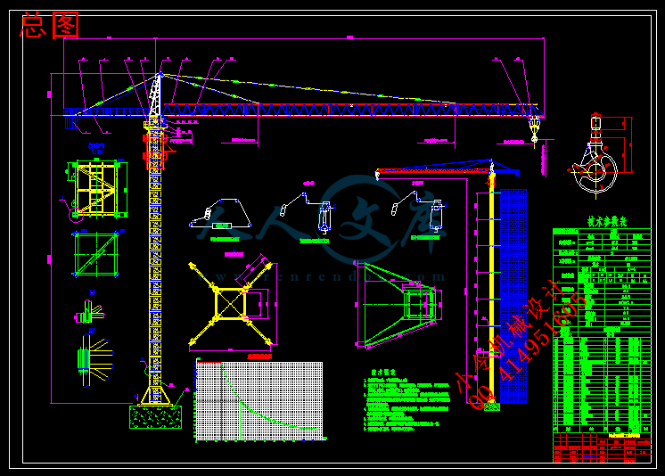
 QTZ125塔式起重机总体 臂架、变幅机构设计(63m吊臂)【全套CAD图纸+WORD毕业论文】【工程机械】
QTZ125塔式起重机总体 臂架、变幅机构设计(63m吊臂)【全套CAD图纸+WORD毕业论文】【工程机械】
收藏
资源目录

压缩包内文档预览:
编号:395874
类型:共享资源
大小:16.39MB
格式:RAR
上传时间:2015-01-14
上传人:好资料QQ****51605
认证信息
个人认证
孙**(实名认证)
江苏
IP属地:江苏
45
积分
- 关 键 词:
-
qtz125
塔式起重机
总体
整体
臂架
机构
设计
63
吊臂
全套
cad
图纸
word
毕业论文
工程机械
- 资源描述:
-
【温馨提示】 购买原稿文件请充值后自助下载。
[全部文件] 那张截图中的文件为本资料所有内容,下载后即可获得。
预览截图请勿抄袭,原稿文件完整清晰,无水印,可编辑。
有疑问可以咨询QQ:414951605或1304139763




1、毕业设计(论文)目的:
本次毕业设计是对机械专业学生在毕业前的一次全面训练,目的在于巩固自己所学知识并把所学知识运用到实际设计当中,真正明白知识如何应用。训练学生综合运用所学知识分析和解决问题的能力。将所学知识应用与实际培养独立工作能力。毕业设计要求每个学生在工作过程中,要独立思考,刻苦钻研,有所创新、解决相关技术问题。通过毕业设计,使学生掌握塔式起重机的总体设计、塔身的设计、整体稳定性计算等内容,为今后步入社会、走上工作岗位打下良好的基础。
2、毕业设计(论文)任务内容和要求(包括原始数据、技术要求、工作要求等):
(1)设计任务:
①总体参数的选择(QTZ125级别)
②结构形式
(2)总体设计
①主要技术参数性能
②设计原则
③平衡重的计算
④塔机的风力计算
⑤整机倾翻稳定性的计算
(3)变幅机构的设计和计算
① 建立变幅机构的数学模型
② 钢丝绳的选择和校核
③ 卷筒的设计和绕绳系统的计算
④ 验算实际变幅速度
⑤ 电动机的选择
⑥ 蜗轮蜗杆减速器的设计
(4) 臂架的设计和计算
① 分析单双吊点的优缺点
② 吊点位置的选择
③ 臂架结构参数选择
④ 臂架主参数选择与计算
(5)变幅的设计和计算
(6) 要求
① 主要任务:学生应在指导教师指导下独立完成一项给定的设计任务,编写符合要求的设计说明书,并正确绘制机械与电气工程图纸,独立撰写一份2500~~3500字毕业设计小论文,并绘制有关图表。
② 知识要求:学生在毕业设计工作中,应综合运用多学科的理论、知识与技能,分析与解决工程问题。通过学习、钻研与实践,深化理论认识、扩展知识领域、延伸专业技能。
③ 能力培养要求:学生应学会依据技术课题任务,完成资料的调研、收集、加工与整理,正确使用工具书;培养学生掌握有关工程设计的程序、方法与技术规范,提高工程设计计算、图纸绘制、编写技术文件的能力;培养学生掌握实验、测试等科学研究的基本方法;锻炼学生分析与解决工程实际问题的能力。
④ 综合素质要求:通过毕业设计,学生应掌握正确的设计思想;培养学生严肃认真的科学态度和严谨求实的工作作风;在工程设计中,应能树立正确的生产观、经济观与全局观。
⑤ 设计成果要求:
1)凡给定的设计内容,包括说明书、计算书、图纸等必须完整,不得有未完的部分,不应出现缺页、少图纸现象。
2)对设计的全部内容,包括设计计算、机械构造、工作原理、整机布置等,均有清晰的了解。对设计过程、计算步骤有明确的概念,能用图纸完整的表达机械结构与工艺要求,有比较熟练的认识图纸能力。对运输、安装、使用等亦有一般了解。
3)说明书、计算书内容要精练,表述要清楚,取材合理,取值合适,设计计算步骤正确,数学计算准确,各项说明要有依据,插图、表格及字迹均应工整、清楚、不得随意涂改。制图要符合机械机械制图标准,且清洁整齐。小论文要符合论文书写规范。
4)对国内外塔式起重机情况有一般的了解,对各种塔式起重机有一定的分析、比较能力。
其他各项应符合本资料有关部分提出的要求。
3、毕业设计(论文)成果要求(包括图表、实物等硬件要求):
① 计算说明书一份
内容包括:设计任务要求的选型、设计计算内容、毕业实习报告等。作到内容完整,论证充分(包括经济性论证),字迹清楚,插图和表格正规(分别进行统一编号)、批准,字数要求不少于2万字;撰写中英文摘要;提倡学生应用计算机进行设计、计算与绘图。
② 图纸一套
1)总图一张(0号)
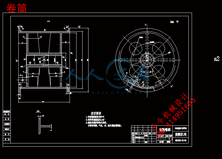
2)变幅机构图一张(0号)
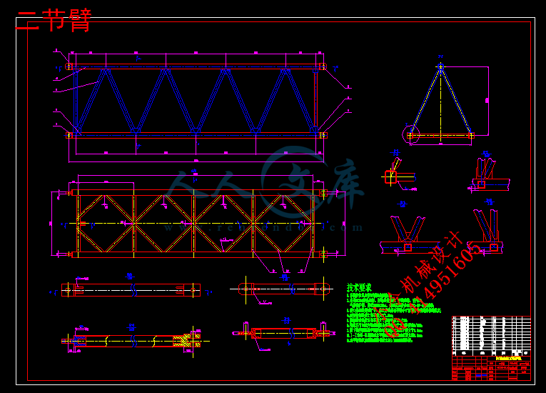
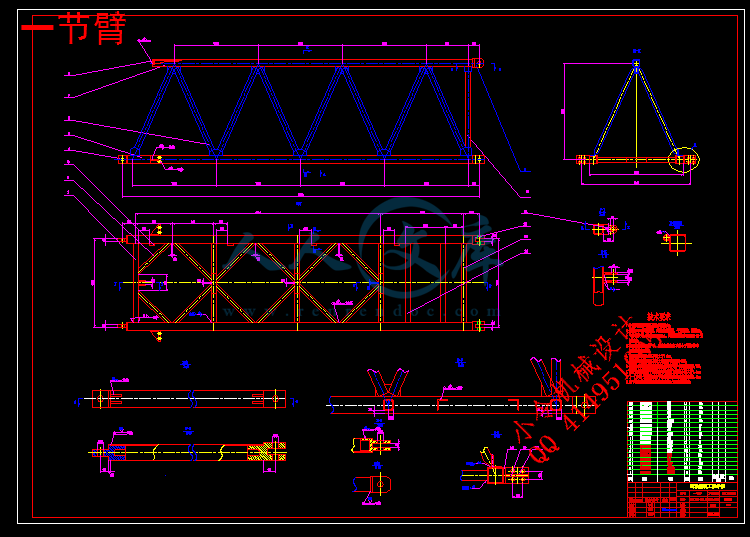
3)臂架图一张(0号)
4)零件图至少三张(2,3,4号)
③ 3000字左右的毕业设计小论文一篇
4、主要参考文献:
要求按国标GB 7714—87《文后参考文献著录规则》书写。
[1] 哈尔滨建筑工程学院主编.工程起重机.北京:中国建筑工业出版社
[2] 董刚、李建功主编.机械设计.机械工业出版社
[3] 机械设计手册.化学工业出版社(5册)
[4] GB/T9462—1999 塔式起重机技术条件
[5] GB/T13752—1992 塔式起重机设计规范
[6] GB5144—1994 塔式起重机安全规程
[7] 濮良贵、纪名刚主编.机械设计(第八版).高等教育出版社
目录
第一章 前言··················································································1
1.1塔式起重机概述············································································1
1.2塔式起重机的发展趋势····································································3
第二章 总体设计············································································4
2.1 概述························································································4
2.2 总体设计方案的确定······································································5
2.2.1金属结构·················································································5
2.2.2工作机构················································································25
2.3 总体设计原则············································································29
2.3.1 整机工作级别··········································································32
2.3.2 机构工作级别··········································································32
2.3.3 主要技术性能参数····································································32
2.4平衡臂与平衡重的计算···································································33
2.5起重特性曲线·············································································35
2.6塔机风力计算·············································································37
2.6.1工作工况Ⅰ············································································38
2.6.2工作工况Ⅱ·············································································42
2.6.3工作工况Ⅲ·············································································44
2.6.4非工作工况Ⅳ···········································································46
2.7整机的抗倾翻稳定性·····································································48
2.7.1工作工况Ⅰ·············································································49
2.7.2工作工况Ⅱ·············································································50
2.7.3非工作工况Ⅲ···········································································51
2.7.4工作工况Ⅳ·············································································51
第三章 塔身的设计计算·································································52
3.1塔身的总体模型···········································································52
3.2 塔身的受力分析及验算··································································53
3.2.1.塔身的受力分析·······································································53
3.2.2 塔身内力计算及组合··································································56
3.2.3 塔身整体稳定性和强度验算··························································59
第四章 变幅机构的设计和计算························································71
4.1变幅机构的形式··········································································71
4.2 确定卷筒尺寸············································································71
4.2.1 卷筒名义直径··········································································71
4.2.2 多层绕卷筒相关参数计算····························································72
4.3选择电动机、减速器、制动器、联轴器····················································72
4.3.1选择电动机·············································································72
4.3.2 选择减速器············································································73
4.3.3 变幅机构制动器的选择·······························································74
4.3.4变幅机构联轴器的选择································································75
4.4. 验算变幅速度···········································································77
4.5验算起、制动时间验算····································································77
4.6电动机发热校验···········································································79
4.7 校验卷筒强度············································································80
第五章 变幅小车的设计·······························································80
5.1 变幅小车的形式··········································································80
5.2 变幅小车的设计··········································································81
5.2.1 绳索牵引式小车构造及其驱动方式················································81
5.2.2运行小车牵引力计算···································································82
5.2.3 牵引绳最大张力·······································································85
5.2.4 选择牵引绳············································································86
5.2.5 牵引卷筒计算··········································································86
第六章 毕业设计小结····································································89
致谢····························································································90
参考书目·······················································································92
- 内容简介:
-
1496IEEE TRANSACTIONS ON SYSTEMS, MAN, AND CYBERNETICSPART A: SYSTEMS AND HUMANS, VOL. 42, NO. 6, NOVEMBER 2012Using Machine Vision and Hand-Motion Controlto Improve Crane Operator PerformanceKelvin Chen Chih Peng, William Singhose, and Purnajyoti BhaumikAbstractThe payload oscillation inherent to all cranes makesit challenging for human operators to manipulate payloadsquickly, accurately, and safely. Manipulation difficulty is alsoincreased by nonintuitive crane-control interfaces. This paperdescribes a new interface that allows operators to drive a craneby moving a hand-held device (wand or glove) freely in space.A crane-mounted camera tracks the movement of the hand-helddevice, the position of which is used to drive the crane. Two controlarchitectures were investigated. The first uses a simple feedbackcontroller, and the second uses feedback and an input shaper.Two operator studies demonstrate that hand-motion crane controlis faster and safer than using a standard push-button pendentcontrol.IndexTermsControlinterface,cranes,inputshaping,machine vision, oscillation.I. INTRODUCTIONCRANES PLAY a key role in maintaining the economicvitality of modern-day industry. Their importance can beseen at shipyards, construction sites, and warehouses and ina wide variety of material-handling applications. The effec-tiveness of crane manipulation is an important contributor toindustrial productivity, low production costs, and worker safety.Oneinherentpropertyofcranesthatisdetrimentaltoefficientoperation is the natural tendency for the payload to oscillate likeapendulum, adoublependulum 1,orwitheven morecomplexoscillatory dynamics 2. Significant effort has been made todevelop control schemes to reduce the oscillatory responsefrom both issued commands and external disturbances 39.There has also been research in controlling cranes that containrotational joints, which adds an extra level of complexity dueto their nonlinear dynamics 1013. Operators who manip-ulate a crane using traditional interfaces such as push-buttonpendents benefit from oscillation-suppression technology. Theygenerate safer (less collisions with obstacles) and more efficientcrane motions (faster task completion times and less operatorbutton pushes) than operators without such compensation 10,1416.Manuscript received September 26, 2010; revised April 7, 2011, June 10,2011, and February 9, 2012; accepted April 6, 2012. Date of publicationJune 8, 2012; date of current version October 12, 2012. This work wassupported in part by Siemens Industrial Automation, by the ManufacturingResearch Center, Georgia Institute of Technology, and by Boeing Research andTechnology. This paper was recommended by Associate Editor E. J. Bass.The authors are with the Woodruff School of Mechanical Engineering,Georgia Institute of Technology, Atlanta, GA 30332 USA (e-mail: kccpeng; Singhose; pjbhaumik).Color versions of one or more of the figures in this paper are available onlineat .Digital Object Identifier 10.1109/TSMCA.2012.2199301Fig. 1.Standard push-button pendent crane control.In addition to facing the challenges of controlling large-amplitude lightly-damped payload swing, operators must alsomaster nonintuitive control interfaces. Fig. 1 shows the pendentcontrol of a typical overhead crane. The operator must be adeptin the cognitive process of transferring the desired manipulationpath into a sequence of button presses that will produce thedesired crane motion. For example, if the operator wants todrive the crane through a cluttered workspace, then the desiredpath must be mapped into a sequence of events where the“forward (F),” “backward (B),” “left (L),” and “right (R)”buttons are pushed at the correct time and in the correct se-quence. Furthermore, as operators move through the workspaceto drive the crane and monitor its progress, they may rotatetheir bodies and change the direction they are facing. In suchcases, the “forward” button causes motion to the left, right,or even backward. As an additional challenge, the operatorcan only directly drive the overhead trolley, not the payload.Therefore, the operator must account for the time lag betweenthe commanded motion of the trolley, which can be manymeters overhead, and the delayed oscillatory response of thepayload.While significant strides have been made to improve theoperational efficiency of cranes by controlling the dynamicresponse to issued commands, relatively little consideration hasbeen given to the way in which operators issue those commands17. It has been proven that interfaces that are tailored to thecognitive processes associated with specific control systemshave beneficial effects 1820. For example, in the fieldof laparoscopic surgery, medical robots such as the da Vinciimprove on the traditional procedure by allowing surgeons tooperate in a more ergonomic manner and with less cognitiveload 21, 22. The controls move in the same direction asthe end effectors for da Vinci, unlike traditional laparoscopic1083-4427/$31.00 2012 IEEEPENG et al.: USING MACHINE VISION AND MOTION CONTROL TO IMPROVE CRANE OPERATOR PERFORMANCE1497procedures where surgeons have to reverse map the controlsdue to the instruments pivot point at the point of insertion.This paper presents a novel control interface that allows anoperator to drive a crane by moving a hand-held device inspace. Machine vision is used to track the position of the device(a wand or a glove), which is then used to generate thecommand signal to drive the crane. The hand-motion controlinterface is well tailored to the task of driving a crane througha cluttered workspace because it eliminates the cognitive map-pingprocessthatisnecessarywithtraditionalcontrolinterfaces.Asaresult,operatorsnolongerneedtoaccount forthedirectionin which they are facing. The manual dexterity required forsafe and efficient operation is also reduced. Additionally, thecontrol algorithm minimizes payload swing without signifi-cantly slowing the system response. Therefore, the burden ofmanually reducing payload oscillation is removed. This allowsthe operator to concentrate solely on the path planning and finalpositioning of the payload.Hand-motion control offers other cognitive advantages overtraditional interfaces. There are two primary divisions of cogni-tive control: analytic problem solving and perceptual process-ing 23. Perceptual processing tends to be faster and can beperformed in parallel, while analytic processing takes longerand typically progresses serially. Analytic problem solving alsotends to be more prone to error 23, 24. The results of manystudies also suggest that people prefer, and adopt, perceptualprocessing when possible 16, 23, 25, 26. From thisperspective, hand-motion control helps operators by loweringthe cognition level required to drive the crane. Operators nolonger need to think analytically about the sequence of buttonsto push or to account for the swinging payload; they only needto move the hand-held device to the desired position or alonga desired path. This allows the operators to perform simplerperceptual processing.Themajorcontributionofthispaperisthenovelhand-motioncontrol interface. The benefits of this interface are validated byhuman operator studies. Section II describes the novel inter-faces (the wand and glove). The control algorithms that are usedin conjunction with the interfaces are discussed in Section III.This is followed by the operator studies in Section IV andconclusions in Section V.II. INTERFACES FORHAND-MOTIONCRANECONTROLThe application investigated in this paper is for a single-pendulum point-mass payload that is suspended from a motor-ized overhead crane. The 10-ton industrial bridge crane showninFig.2wasusedforexperimentalverifications.Abridgecraneconsists of a fixed overhead runway, a bridge that travels alongthe runway, and a trolley that runs along the bridge. Laserrange sensors measure the trolley position along the runwayand the bridge. The hook, which represents the payload, issuspendedfromthetrolleybycables.ASiemensprogrammablelogic controller is used to control the motor drives and actsas the central control unit. Commands to the crane can beissued with a push-button control pendent, the wand or glovefor hand-motion control, or other devices 17. A downward-pointing Siemens Simatic VS723-2 camera mounted on theFig. 2.Typical bridge crane.Fig. 3.Driving a crane by moving a reflective wand.trolley measures the position of the hook. Reflectors mountedon the topside of the hook aid vision-detection algorithms 27.There are two hand-held devices for hand-motion cranecontrol: 1) The wand, shown in Fig. 3, is a reflective ballmounted to the end of a hand-held pole, and 2) the glove,shown in Fig. 4, has a circular reflector attached to the backside.Fig. 5 shows a schematic diagram of hand-motion controlusing machine vision. The crane-mounted camera is used toconcurrentlytrackthepositionsofthewand/gloveandthehook.Because all reflectors appear as bright blobs in the cameraimage, a K-means clustering algorithm is used to distinguishthe wand/glove reflectors from the hook reflectors 28. Thecamera refresh rate is approximately 140 ms. The position ofthe wand/glove relative to the crane is used to generate an errorsignal to drive the overhead trolley.1498IEEE TRANSACTIONS ON SYSTEMS, MAN, AND CYBERNETICSPART A: SYSTEMS AND HUMANS, VOL. 42, NO. 6, NOVEMBER 2012Fig. 4.Driving a crane by moving a reflective glove.Fig. 5.Schematic of hand-motion crane control.III. HAND-MOTIONCRANECONTROLLERSThree control architectures were investigated. First, the stan-dard push-button pendent controller was used as the baselinefor performance comparisons. Then, a proportionalderivative(PD) feedback controller was investigated for its suitability inhand-motion crane control. Finally, an input shaper was addedto the PD controller in order to reduce payload swing.Note that, from the perspective of the control architecture,the wand and the glove are identical. Both devices are used tocommunicate the operators desired position to the controller.For this reason, there is no distinction between the wand andglove in the simulation and experimental verification resultsthat are presented in this section. However, in terms of er-gonomics during operation, the wand has a greater reach andcan drive the crane toward tight spaces, such as corners. On theother hand, the glove sacrifices range of reach for a smaller sizeand ease of use.Fig. 6.Standard pendent controller.Fig. 7.Standard push-button pendent control response.Fig. 8.PD hand-motion controller.A. Standard Push-Button Pendent ControlThe block diagram for standard pendent control is shownin Fig. 6. The operator analyzes the workspace, considers therequired manipulation goal, and then decides on a course ofaction. This plan is then implemented by pushing buttons onthe control pendent. These buttons send energy to the motorsand move the overhead crane trolley. The suspended payload ismoved indirectly by the motion of the trolley.Computer-simulated responses for point-to-point movementsof approximately 2 and 3 m using the pendent controller areshown in Fig. 7. Pressing a pendent button for a certain amountof time issues a trapezoidal velocity command to the cranemotors. Due to the pendulum-like nature of the payload, thistype of trolley movement will, in general, induce significantpayload oscillations.B. PD Hand-Motion ControlThe well-known and popular PD controller represents one ofthe simplest forms of feedback control. It is the most commonlyused feedback method in industry and has been applied to thecontrol of cranes 29, 30. It provides a realistic choice forhand-motion crane controllers. The PD hand-motion controlblock diagram is shown in Fig. 8. The position of the wandor glove is compared to the position of the overhead crane(neglecting the vertical height difference) to generate the errorsignal e. The command generator converts the error signal(a positional measurement) into a velocity command that canbe sent to the motor drives. If e is within the designed rangespecified by e0and e100, then the command generator linearlyPENG et al.: USING MACHINE VISION AND MOTION CONTROL TO IMPROVE CRANE OPERATOR PERFORMANCE1499Fig. 9.Simulated PD controller with low gains.scales e. Otherwise, the command generator outputs either 0%or 100%. The values for e0and e100were 0.25 and 1.0 m.These were selected based on comfortable distances at whichthe crane followed the operator. The command generator isdescribed asCommand =?0%: e e0100% ee0e100e0: e0 e e100100%: e e100.(1)A PD control law is then applied, and the result is passedthrough a saturator to ensure that crane velocity and accel-eration limits are not exceeded. Note that the position of thecrane trolley, rather than of the payload, is used for feedback.This is because, in practice, sensing the position of the trolley(using laser range sensors) is much more reliable than sensingof the payload (using machine vision). Furthermore, the single-pendulum payload is an inherently stable plant: The payloadwill always come to rest directly beneath a stationary crane.Therefore, correct final positioning of the crane trolley ensurescorrect final positioning of the payload.1) Simulation Verification: A crucial design challenge is theselection of PD gains. Computer simulations were constructedto aid the gain-selection process. Hand-motion trajectories werespecified as ramps in position with gradients equivalent to themaximum velocity of the 10-ton industrial crane (0.3577 m/s).This is approximately the speed of a slow walk and mimics thetypical hand-motion trajectories from a human operator.Figs. 9 and 10 show the simulation results for PD hand-motion controllers with low and high feedback gains, respec-tively. These two figures show the inherent tradeoff in using thePD controller: With low gains, the crane was slow to respond,but the payload oscillation was small; with high gains, the cranemoved quickly but at the expense of large payload oscillations.2) Experimental Verification: The hand-motion control sys-tem was implemented on the 10-ton bridge crane. Thewand/glove trajectories produced by human operators weresimilar to those used in the simulations. The ramp gradientwas approximately equivalent to the maximum velocity of thecrane, and the move distance was approximately 2 m for thetests reported here.Fig. 11 shows an operator using hand-motion control to startand stop the crane. To start moving, the operator can exposeFig. 10.Simulated PD controller with high gains.Fig. 11.Starting and stopping with hand-motion control.Fig. 12.Experimental PD controller with low gains.the wand/glove to the camera at some distance away from thecrane. When the crane approaches the desired position, theoperator lowers the wand/glove, which becomes undetectableby the camera. When the camera is unable to locate the positionof the wand/glove, e is set to zero. Because the position of thewand/glove may be unknown at certain times, there are breaksin the curves that are labeled “Wand/Glove” in the experimentalresponse plots.Figs. 12 and 13 show the experimental results for PD hand-motion controllers with low and high feedback gains usingthe glove interface, respectively. The experimental data re-inforce the results that were established by the simulations:Low gains produced slow crane movements and small payloadoscillations, while high gains yielded fast crane movementsbut large payload oscillations. For safety reasons, minimizingpayload oscillation is normally a higher priority than fast crane1500IEEE TRANSACTIONS ON SYSTEMS, MAN, AND CYBERNETICSPART A: SYSTEMS AND HUMANS, VOL. 42, NO. 6, NOVEMBER 2012Fig. 13.Experimental PD controller with high gains.Fig. 14.PD with input shaper hand-motion controller.movements. Therefore, practical implementations of PD hand-motion controllers should only use low gains.C. PD With Input Shaper Hand-Motion ControlSection III-B demonstrated the inherent weakness in usingPD hand-motion controllers (the tradeoff between low and highgains). However, performance can be improved with the addi-tion of an input shaper that modifies the shape of the commandsignal to reduce oscillation. Fig. 14 shows the new controlblock diagram that shows an input shaper inserted between thesaturator and the crane blocks.1) Input Shaping: Input shaping is a technique that reducesthe residual vibration of flexible systems by properly shapingthe commands. This is accomplished by convolving the base-line input command with a series of impulses, known as aninput shaper. The result is a shaped command that will reduceresidual vibration.In order to determine the impulse amplitudes and time loca-tions of an input shaper, certain design constraints must be sat-isfied. The primary design constraint is a limit on the amplitudeof vibration caused by the shaper. The normalized percentageresidual vibration (PRV) amplitude of an underdamped second-order system from a sequence of n impulses is given by 31PRV = V (,) = etn?C(,)2+ S(,)2(2)whereC(,) =n?i=1Aieticos(ti?1 2)(3)S(,) =n?i=1Aietisin(ti?1 2)(4)Fig. 15.Simulated PD with input shaper controller.Fig. 16.Experimental PD with input shaper controller. is the natural frequency of the system, is the dampingratio, and Aiand tiare the ith impulse amplitude and time,respectively.Equation (2) gives the ratio of vibration with input shapingto that without input shaping. A constraint on residual vibrationamplitude can be formed by setting (2) less than or equal to atolerable level of residual vibration at the modeled natural fre-quency and damping ratio 32. For the simplest zero vibration(ZV) shaper, the tolerable amount of vibration is set to zero.This results in a shaper of the form 31, 33ZV =?Aiti?=?11+KK1+K012?(5)whereK = e12.(6)2) Simulation and Experimental Verifications: The goal ofcombining high-gain PD feedback with a ZV input shaperis to obtain fast crane response and low-amplitude payloadoscillations. The hand-motion controller in this section useshighPDgains (identicaltotheonesfromSectionIII-B)tomovethe crane trolley quickly, combined with a ZV input shaper tocancel payload oscillations.Figs. 15 and 16 show the simulated and experimental re-sponses of the controller, respectively. The experimental datawere obtained using the glove interface. Clearly, the craneresponse was fast, yet with very little payload oscillation.PENG et al.: USING MACHINE VISION AND MOTION CONTROL TO IMPROVE CRANE OPERATOR PERFORMANCE1501Fig. 17.Overhead view of obstacle course 1.Fig. 18.Obstacle course 1 completion times.Furthermore, the lag in rise time introduced by the input shaperwas hardly noticeable. The crane responds with nearly identicalspeeds with or without input shaping. Therefore, this version ofthe hand-motion controller is free to use high PD gains becausethe input shaper eliminates payload oscillations.IV. OPERATORSTUDIESThis section presents the results from two studies that wereconducted to compare the operating efficiency of pendent con-trol versus hand-motion control. In each study, the goal was tomove the payload (i.e., the crane hook) from start to finish asquickly as possible without collisions with obstacles.A. PD Hand-Motion ControlAn overhead view of the obstacle course is shown in Fig. 17.The start and end zones are indicated by the rectangle andcircle, respectively. The obstacles are arranged such that thefastest route required diagonal crane movements (simultaneousmovement in both the trolley and bridge axes). Twelve noviceoperators completed the obstacle course using the followingcontrol interfaces:1) standard push-button pendent;2) wand control with low PD gains and no input shaping(recall that practical implementations of PD hand-motioncontrollers must use low gains to avoid large amplitudepayload oscillations).Fig. 19.Obstacle course 1 collisions.Fig. 20.Overhead view of obstacle course 2.Fig. 21.Exemplary obstacle course 2 payload responses.Fig. 18 shows the course completion times for each operator.The average completion time using the pendent was 97 s. Theaverage completion time using the wand was only 46 s, whichis a 53% improvement. A one-way repeated-measure analysis-of-variance (ANOVA) test indicates that the improvementin completion time was statistically significant (F = 17. 67;P = 0. 00148).Fig. 19 plots the number of collisions that occurred duringeach trial. Using pendent control, all operators suffered at leastone collision, and the average number of collisions was 5.1.Using wand control, the average number of collisions was only0.92, which is an 81% improvement. A one-way repeated-measure ANOVA test indicates that the reduction in collisionswas statistically significant (F = 19. 81; P = 0. 00098).1502IEEE TRANSACTIONS ON SYSTEMS, MAN, AND CYBERNETICSPART A: SYSTEMS AND HUMANS, VOL. 42, NO. 6, NOVEMBER 2012Fig. 22.Obstacle course 2 completion times.Fig. 23.Obstacle course 2 collisions.B. PD With ZV Shaper Hand-Motion ControlThe obstacle course used in this study is shown in Fig. 20.The start and end zones are indicated by the rectangle and cir-cle, respectively. Ten novice operators completed the obstaclecourse using the following control interfaces:1) standard pendent control;2) glove control with high PD gains and ZV input shaper;3) wand control with high PD gains and ZV input shaper.Fig. 21 shows an overhead view of typical payload responsesfor a single operator using the pendent and glove. Comparedto using the pendent, using the glove significantly reduced thepayload swing and allowed the operator to move the payloadmore efficiently.Fig. 22 shows the course completion times for each operator.The average completion time using the pendent was 77 s. Theaverage completion time using the glove was 24 s (68.8%improvement over the pendent), and that using the wand was30s(61%improvementoverthependent).Aone-wayrepeated-measure ANOVA test indicates that there were statistically sig-nificant differences in the completion times of the three controlmethods (F = 63. 88; P . 0001). A 95%-confidence-intervalTukey test indicated that there were statistically significantdifferences between the pendent and wand (P . 0001) andbetween the pendent and glove (P . 0001). However, therewas no significant difference between the wand and the glove(P = 0. 46).Fig. 23 plots the number of collisions that occurred duringeach trial. Using pendent control, many operators collided thepayload with the obstacle. The average number of collisionswas 0.9. However, all operators were able to avoid the obstacleusing the glove and wand, corresponding to 100% improve-ments over the pendent. A one-way repeated-measure ANOVAtest indicates that there were statistically significant differencesin the number of collisions using the three control methods(F = 10. 57; P = 0. 00092). A 95%-confidence-interval Tukeytest indicated that there were statistically significant differencesbetween the pendent and wand (P = 0. 0024) and between thependent and glove (P = 0. 0024).V. CONCLUSIONCrane controllers based on operator hand motion were suc-cessfully installed on an industrial bridge crane. A crane-mounted camera tracks the position of a hand-held device (awand or a glove), which is moved by the operator throughthe desired trajectory. The crane then follows the wand/glove.Three types of controllers have been investigated: 1) standardpendent control (for baseline comparisons); 2) PD hand-motioncontrol; and 3) PD with input-shaping hand-motion control.Two operator studies based on driving the crane through ob-stacle courses were conducted. The first study showed that PDcontrol using the wand had a 53% improvement in completiontime and an 81% improvement in obstacle avoidance overstandard pendent control. The second study compared pendentcontrol to PD and input-shaping hand-motion control. Usingthe wand and glove, operators demonstrated better than 60%improvements in completion time and 100% improvements inavoiding obstacles compared to using the pendent.REFERENCES1 W. Singhose, D. Kim, and M. Kenison, “Input shaping control ofdouble-pendulum bridge crane oscillations,” J. Dyn. Syst., Meas., Control,vol. 130, no. 3, pp. 034504-1034504-7, May 2008.2 J. Yoon, W. Singhose, J. Vaughan, G. Ramirez, M. Kim, and S. Tawde,“Dynamics and control of crane payloads that bounce and pitch duringhoisting,” in Proc. IDETC/CIE, San Diego, CA, 2009.3 Y. Sakawa and Y. Shindo, “Optimal control of container cranes,”Automatica, vol. 18, no. 3, pp. 257266, May 1982.4 G. P. Starr, “Swing-free transport of suspended objects with a path-controlled robot manipulator,” J. Dyn. Syst., Meas., Control, vol. 107,no. 1, pp. 97100, Mar. 1985.5 D. Strip, “Swing-free transport of suspended objects: A generaltreatment,” IEEE Trans. Robot. Autom., vol. 5, no. 2, pp. 234236,Apr. 1989.6 N. Singer, W. Singhose, and E. Kriikku, “An input shaping controllerenabling cranes to move without sway,” in Proc. ANS 7th Top. MeetingRobot. Remote Syst., Augusta, GA, 1997, vol. 1, pp. 225231.7 K.-S. Hong, J. H. Kim, and K.-I. Lee, “Control of a container crane:Fast traversing, residual sway control from the perspective of controllingan underactuated system,” in Proc. Amer. Control Conf., 1998, vol. 2,pp. 12941298.8 Y.-S. Kim, H.-S. Seo, and S.-K. Sul, “A new anti-sway control scheme fortrolley crane system,” in Conf. Rec. 36th IEEE IAS Annu. Meeting, 2001,vol. 1, pp. 548552.9 Z. Masoud and M. Daqaq, “A graphical approach to input-shaping con-trol design for container cranes with hoist,” IEEE Trans. Control Syst.Technol., vol. 14, no. 6, pp. 10701077, Nov. 2006.10 G. Parker, K. Groom, J. Hurtado, J. Feddema, R. Robinett, and F. Leban,“Experimental verification of a command shaping boom crane controlsystem,” in Proc. Amer. Control Conf., San Diego, CA, 1999, pp. 8690.PENG et al.: USING MACHINE VISION AND MOTION CONTROL TO IMPROVE CRANE OPERATOR PERFORMANCE150311 O. Sawodny, A. Hildebrandt, and K. Schneider, “Control design for therotation of crane loads for boom cranes,” in Proc. IEEE ICRA, 2003,vol. 2, pp. 21822187.12 J. Neupert, T. Mahl, O. Sawodny, and K. Schneider, “A nonlinearcontrol strategy for boom cranes in radial direction,” in Proc. ACC, 2007,pp. 2530.13 C. Ko, J. Chiou, C. Y. Gau, S. Lee, and W. Chang, “Tower crane vibrationsuppression using generalized input shaping,” Int. J. Fuzzy Syst., vol. 6,no. 1, pp. 3843, Mar. 2004.14 A. Khalid, J. Huey, W. Singhose, and J. Lawrence, “Human operatorperformance testing using an input-shaped bridge crane,” J. Dyn. Syst.,Meas., Control, vol. 128, no. 4, pp. 835841, Dec. 2006.15 D. Kim and W. Singhose, “Performance studies of human operators driv-ing double-pendulum bridge cranes,” Control Eng. Pract., vol. 18, no. 6,pp. 567576, Jun. 2010.16 J. Vaughan, A. Smith, S. J. Kang, and W. Singhose, “Predictive graphicaluser interface elements to improve crane operator performance,” IEEETrans. Syst., Man, Cybern. A, Syst., Humans, vol. 41, no. 2, pp. 323330,Mar. 2011.17 K. L. Sorensen, J. B. Spiers, and W. E. Singhose, “Operational effects ofcrane interface devices,” in Proc. IEEE Conf. Ind. Electron. Appl., Harbin,China, 2007, pp. 10731078.18 S. Guerlain, G. Jamieson, P. Bullemer, and R. Blair, “The MPC elucidator:A case study in the design for human-automation interaction,” IEEETrans. Syst., Man, Cybern. A, Syst., Humans, vol. 32, no. 1, pp. 2540,Jan. 2002.19 G. Jamieson, “Ecological interface design for petrochemical process con-trol: An empirical assessment,” IEEE Trans. Syst., Man, Cybern. A, Syst.,Humans, vol. 37, no. 6, pp. 906920, Nov. 2007.20 S. V. Dam, M. Mulder, and M. van Paassen, “Ecological interface designof a tactical airborne separation assistance tool,” IEEE Trans. Syst., Man,Cybern. A, Syst., Humans, vol. 38, no. 6, pp. 12211233, Nov. 2008.21 R. Taylor, J. Funda, B. Eldridge, S. Gomory, K. Gruben, D. LaRose,M. Talamini, L. Kavoussi, and J. Anderson, “A telerobotic assistant forlaparoscopic surgery,”IEEEEng.Med.Biol. Mag.,vol.14,no.3,pp.279288, May/Jun. 1995.22 G. Ballantyne, “Robotic surgery, telerobotic surgery, telepresence, tele-mentoring,” Surg. Endoscopy, vol. 16, no. 10, pp. 13891402, Oct. 2002.23 J. Reason, Human Errors.Cambridge, U.K.: Cambridge Univ. Press,1990.24 E. Brunswick, Percep
- 温馨提示:
1: 本站所有资源如无特殊说明,都需要本地电脑安装OFFICE2007和PDF阅读器。图纸软件为CAD,CAXA,PROE,UG,SolidWorks等.压缩文件请下载最新的WinRAR软件解压。
2: 本站的文档不包含任何第三方提供的附件图纸等,如果需要附件,请联系上传者。文件的所有权益归上传用户所有。
3.本站RAR压缩包中若带图纸,网页内容里面会有图纸预览,若没有图纸预览就没有图纸。
4. 未经权益所有人同意不得将文件中的内容挪作商业或盈利用途。
5. 人人文库网仅提供信息存储空间,仅对用户上传内容的表现方式做保护处理,对用户上传分享的文档内容本身不做任何修改或编辑,并不能对任何下载内容负责。
6. 下载文件中如有侵权或不适当内容,请与我们联系,我们立即纠正。
7. 本站不保证下载资源的准确性、安全性和完整性, 同时也不承担用户因使用这些下载资源对自己和他人造成任何形式的伤害或损失。

人人文库网所有资源均是用户自行上传分享,仅供网友学习交流,未经上传用户书面授权,请勿作他用。
|
2:不支持迅雷下载,请使用浏览器下载
3:不支持QQ浏览器下载,请用其他浏览器
4:下载后的文档和图纸-无水印
5:文档经过压缩,下载后原文更清晰
|
 川公网安备: 51019002004831号