外文翻译--应用新型延性纤维增强聚合织物对混凝土梁的加固 英文版.pdf

多层钢筋混凝土框架设计【8张图纸】【优秀】

收藏

资源目录
跳过导航链接。
多层钢筋混凝土框架设计【8张图纸】【优秀】.rar
致谢.doc---(点击预览)
目录.doc---(点击预览)
摘要.doc---(点击预览)
多层钢筋混凝土框架设计说明书.doc---(点击预览)
外文翻译--应用新型延性纤维增强聚合织物对混凝土梁的加固 英文版.pdf---(点击预览)
外文翻译--应用新型延性纤维增强聚合织物对混凝土梁的加固 中文版.doc---(点击预览)
参考文献.doc---(点击预览)
9 多层钢筋混凝土框架内力组合.doc---(点击预览)
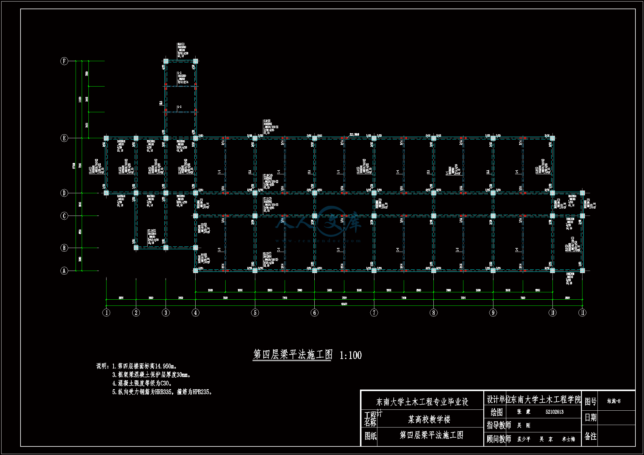
8梁平法图.dwg---(点击预览)
8 多层钢筋混凝土框架地震作用内力计算.doc---(点击预览)
7多层钢筋混凝土框架 风荷载内力计算.doc---(点击预览)
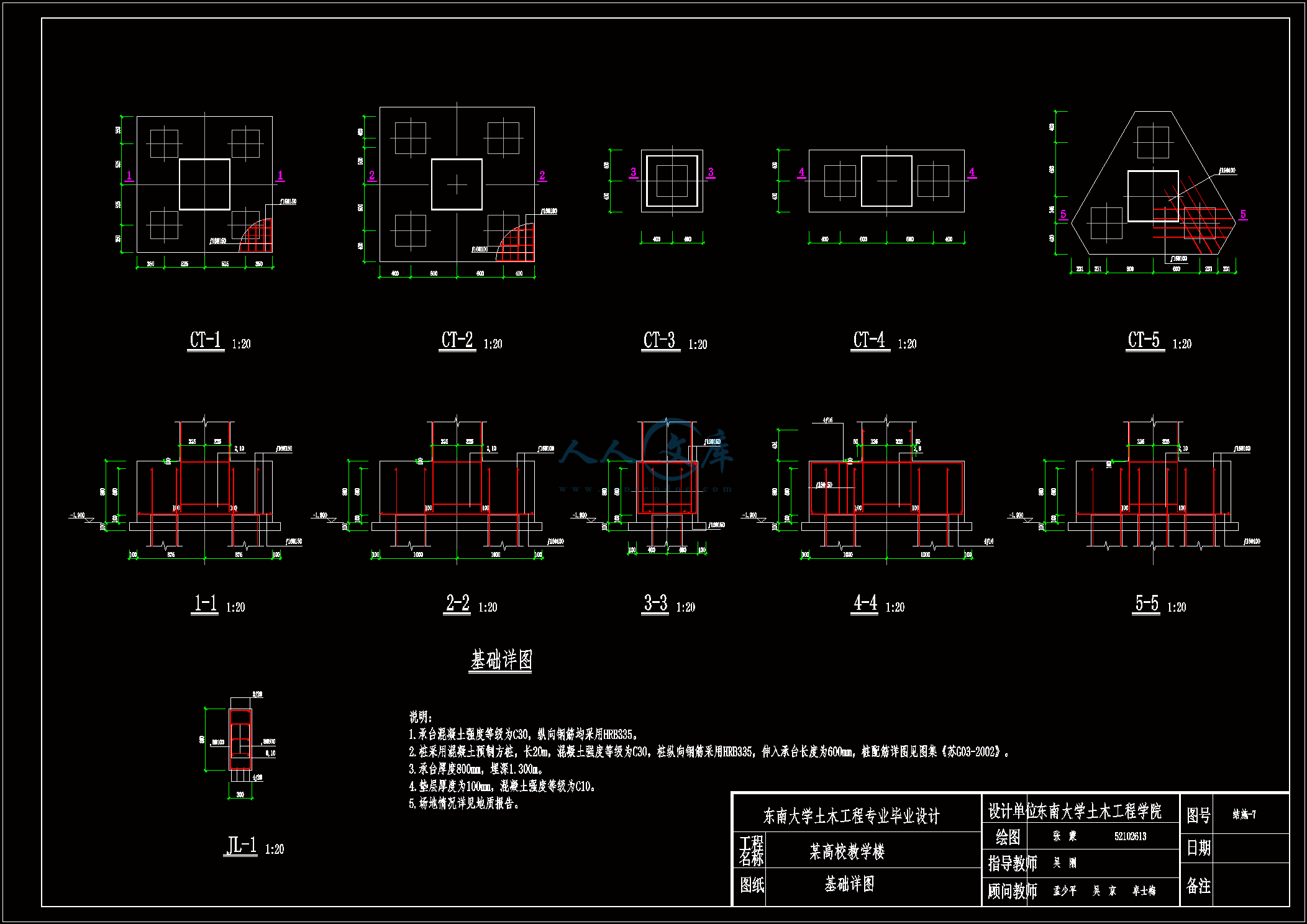
7基础详图.dwg---(点击预览)
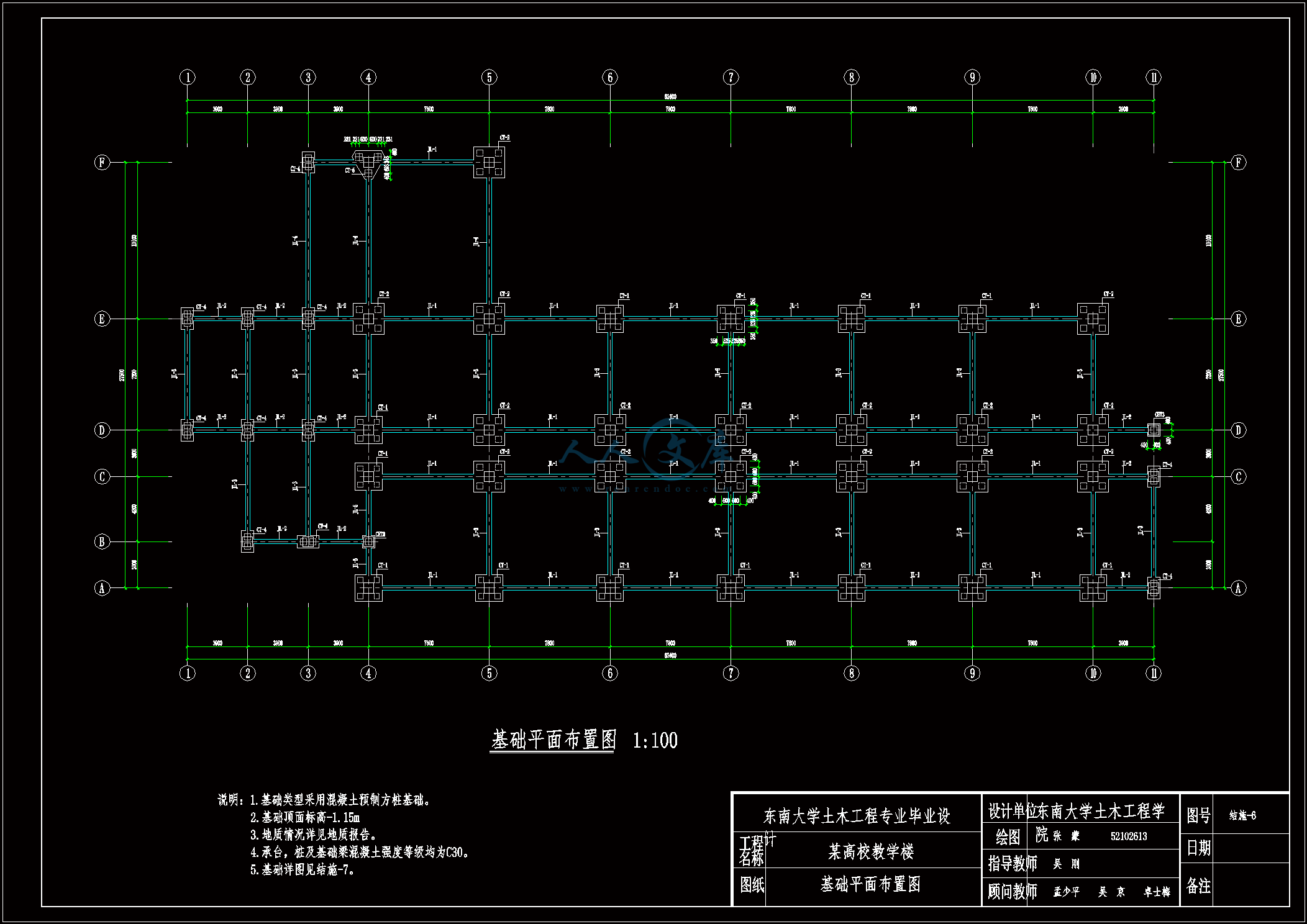
6基础布置.dwg---(点击预览)
6 多层钢筋混凝土框架活荷载内力计算(屋面布活荷载).doc---(点击预览)
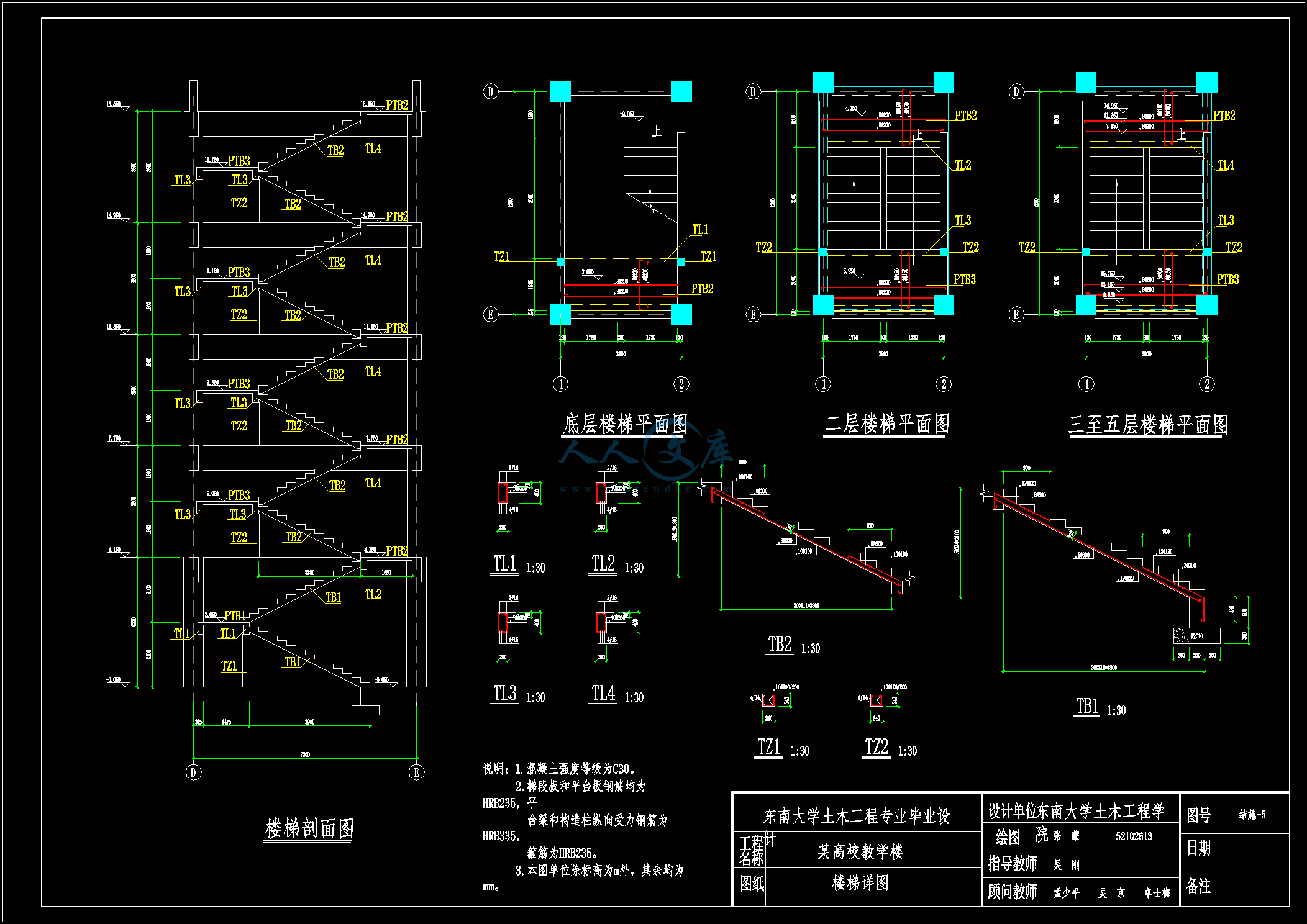
5楼梯.dwg---(点击预览)
5 多层钢筋混凝土框架活荷载内力计算(屋面布雪荷载).doc---(点击预览)
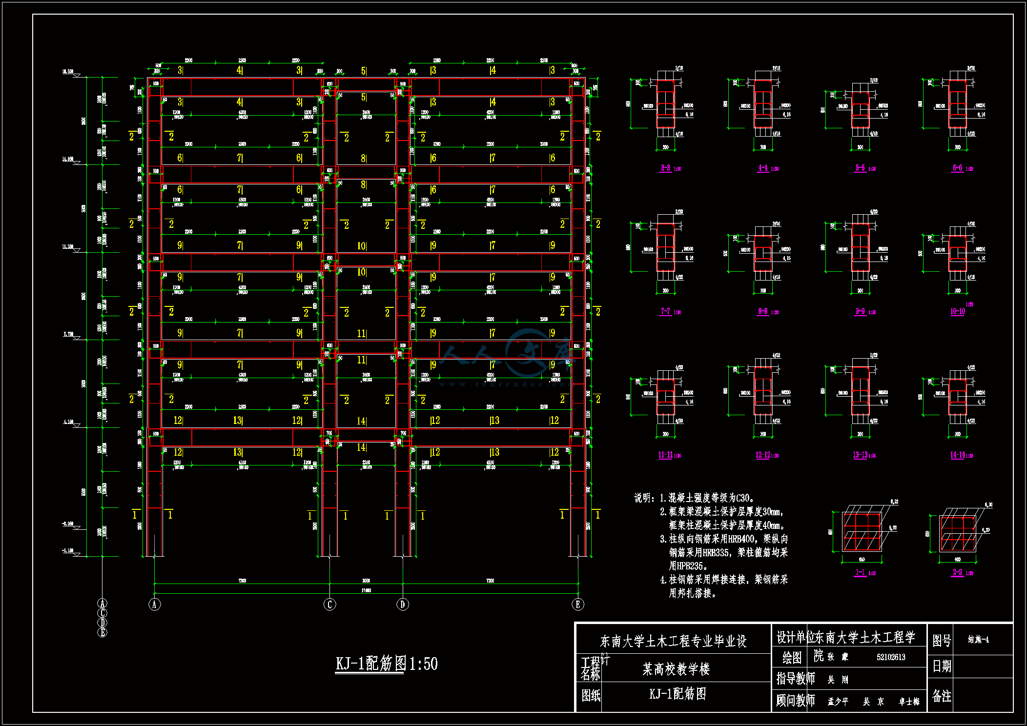
4横向框架.dwg---(点击预览)
4 多层钢筋混凝土框架恒荷载内力计算.doc---(点击预览)
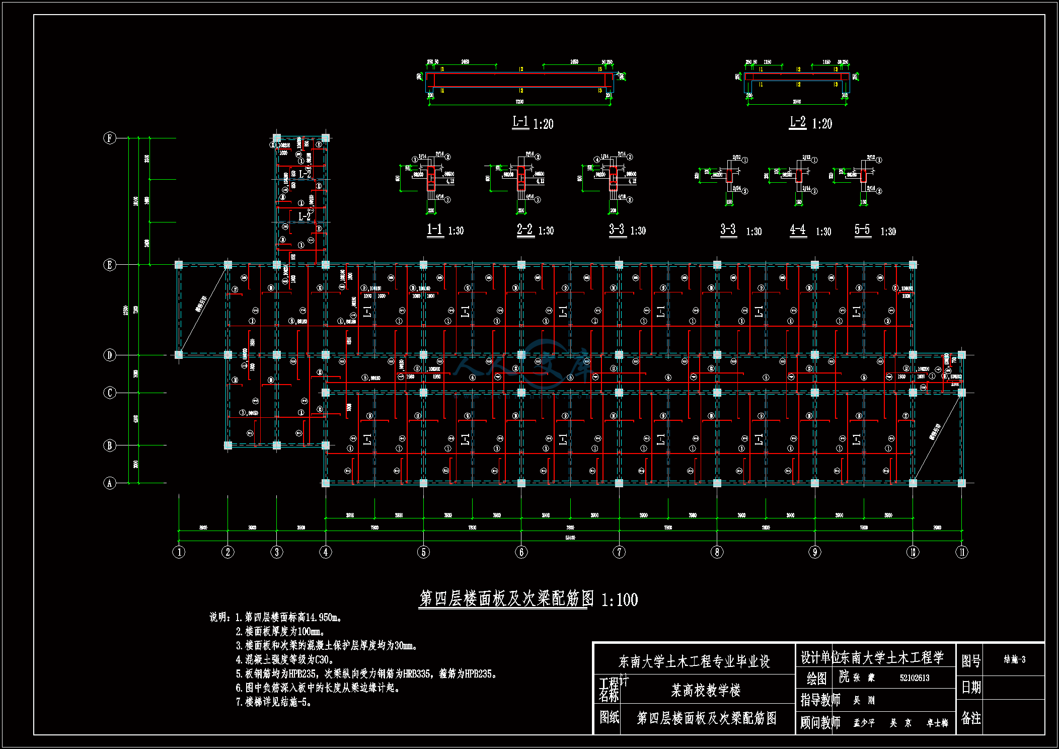
3楼盖.dwg---(点击预览)
3 多层钢筋混凝土框架框架结构布置及计算简图.doc---(点击预览)
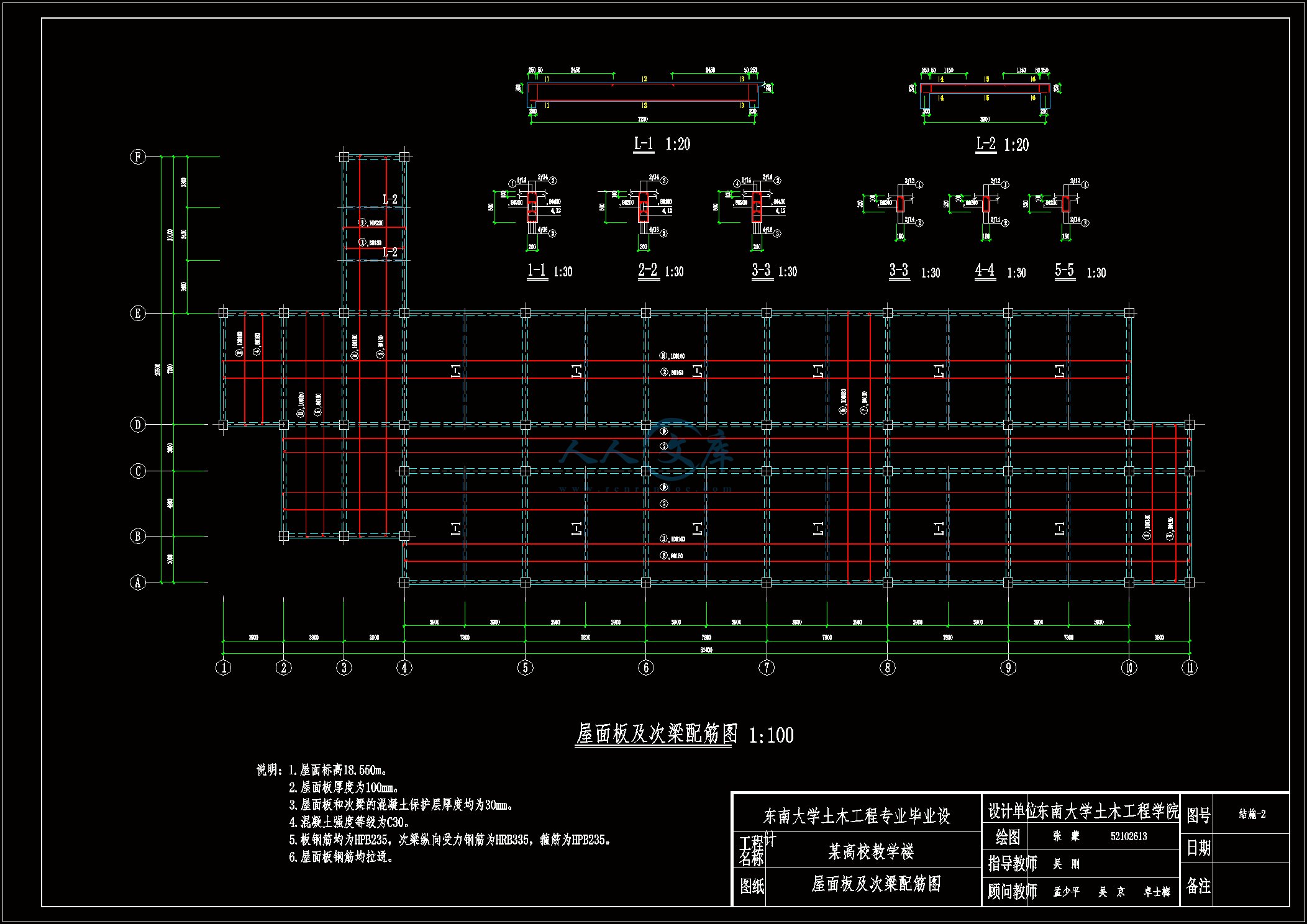
2屋盖.dwg---(点击预览)
2 多层钢筋混凝土框架屋盖、楼盖设计.doc---(点击预览)
1结构布置&模板.dwg---(点击预览)
12 多层钢筋混凝土框架基础设计.doc---(点击预览)
11 多层钢筋混凝土框架楼梯设计.doc---(点击预览)
10 多层钢筋混凝土框架截面设计.doc---(点击预览)
1 工程概况.doc---(点击预览)
内力组合表格
屋盖、楼盖表格
截面设计表格
压缩包内文档预览:
预览图 预览图 预览图 预览图 预览图 预览图 预览图 预览图 预览图
编号:420523    类型:共享资源    大小:2.45MB    格式:RAR    上传时间:2015-03-29 上传人:上*** IP属地:江苏
39
积分
关 键 词:
多层 钢筋混凝土 框架 设计 图纸 优秀 优良
资源描述:

多层钢筋混凝土框架设计

102页 19000字数+说明书+外文翻译+8张CAD图纸【详情如下】

3楼盖.dwg

4 多层钢筋混凝土框架恒荷载内力计算.doc

4横向框架.dwg

5 多层钢筋混凝土框架活荷载内力计算(屋面布雪荷载).doc

5楼梯.dwg

6 多层钢筋混凝土框架活荷载内力计算(屋面布活荷载).doc

6基础布置.dwg

7基础详图.dwg

7多层钢筋混凝土框架 风荷载内力计算.doc

8 多层钢筋混凝土框架地震作用内力计算.doc

8梁平法图.dwg

9 多层钢筋混凝土框架内力组合.doc

内力组合表格

参考文献.doc

外文翻译--应用新型延性纤维增强聚合织物对混凝土梁的加固   中文版.doc

外文翻译--应用新型延性纤维增强聚合织物对混凝土梁的加固   英文版.pdf

屋盖、楼盖表格

截面设计表格

摘要.doc

目录.doc

致谢.doc

1 工程概况.doc

10 多层钢筋混凝土框架截面设计.doc

11 多层钢筋混凝土框架楼梯设计.doc

12 多层钢筋混凝土框架基础设计.doc

1结构布置&模板.dwg

2 多层钢筋混凝土框架屋盖、楼盖设计.doc

2屋盖.dwg

3 多层钢筋混凝土框架框架结构布置及计算简图.doc

目  录

摘要…………………………………………………………………………………Ⅰ

一 工程概况…………………………………………………………………………1

二 屋盖、楼盖设计…………………………………………………………………2

(一)屋盖……………………………………………………………………………2

(二)楼盖……………………………………………………………………………10

三 框架结构布置及计算简图………………………………………………………19

(一)梁柱尺寸………………………………………………………………………19

(二)计算简图………………………………………………………………………19

四 恒荷载内力计算…………………………………………………………………21

(一)恒荷载计算……………………………………………………………………21

(二)恒荷载作用下内力计算………………………………………………………22

五 活荷载内力计算(屋面布雪荷载)……………………………………………33

(一)活荷载计算……………………………………………………………………33

(二)活荷载作用下内力计算………………………………………………………33

六 活荷载内力计算(屋面布活荷载)……………………………………………42

(一)活荷载计算……………………………………………………………………42

(二)活荷载作用下内力计算………………………………………………………42

七 风荷载内力计算…………………………………………………………………51

(一)风荷载计算……………………………………………………………………51

(二)内力计算………………………………………………………………………52

八 地震作用内力计算………………………………………………………………55

(一)重力荷载代表值计算…………………………………………………………55

(二)水平地震作用计算……………………………………………………………56

(三)一榀框架内力计算……………………………………………………………59

九 内力组合…………………………………………………………………………62

(一)梁内力组合……………………………………………………………………62

(二)柱内力组合……………………………………………………………………66

(三)内力设计值汇总………………………………………………………………70

十 截面设计…………………………………………………………………………72

(一)梁截面设计……………………………………………………………………72

(二)柱截面设计……………………………………………………………………75

十一 楼梯设计………………………………………………………………………81

底层楼梯设计………………………………………………………………81

其他层楼梯设计……………………………………………………………84

十二 基础设计………………………………………………………………………89

边柱基础……………………………………………………………………89

中柱基础……………………………………………………………………91

基础梁设计…………………………………………………………………93

致谢…………………………………………………………………………………95

参考文献……………………………………………………………………………96

多层钢筋混凝土框架结构设计

[摘要] 本工程是南京某高校教学楼。为多层钢筋混凝土框架结构。共五层,底层层高4.2米,其他层层高均为3.6米。建筑物总高度为18.6米。

本设计书包括如下部分:

工程概况;

屋盖、楼盖设计;

荷载计算;

框架结构的受力分析、计算和设计;

楼梯设计;

桩基础设计。

设计最终完成八张施工图。

[关键词] 钢筋混凝土,框架,结构设计一 工程概况

  本工程为某高校教学楼。工程为五层现浇钢筋混凝土框架结构。屋面板顶面标高为18.6m。

  工程所在地抗震设防烈度为7度,设计基本地震加速度为0.10g,设计地震分组为第一组,场地类别为Ⅱ类。

  屋面做法:钢筋混凝土现浇板,20mm石灰砂浆抹底,20mm水泥砂浆找平,40~120厚(1%找坡)膨胀珍珠岩保温层,四层作法防水层(一毡二油上铺小石子)。

  楼面做法:钢筋混凝土现浇板,20mm石灰砂浆抹底,20mm水泥砂浆找平,水磨石面层。

  墙身做法:由普通砖砌筑而成,普通砖自重18kN/m3,厚度240mm。

  门窗做法:门为木门,自重0.2 kN/m2,窗为钢窗玻璃窗,自重0.4 kN/m2。

  风荷载标准值0.4kN/m2,雪荷载标准值0.65kN/m2。

  活荷载:上人屋面均布活荷载标准值2.0kN/m2,楼面活荷载标准值2.0kN/m2。

  本设计计算书包括屋盖、楼盖、框架主体结构、楼梯、基础等部分的计算和设计。

二 屋盖、楼盖设计

(一)屋盖

1.设计资料

1)屋面做法:钢筋混凝土现浇板,20mm石灰砂浆抹底,20mm水泥砂浆找平,40~120厚(1%找坡)膨胀珍珠岩保温层,四层作法防水层(一毡二油上铺小石子)

2)屋面荷载:均布活荷载标准值2kN/m2(上人屋面),雪荷载标准值为0.65kN/m2

3)材料:混凝土强度等级为C30;梁内受力纵筋为HRB335,其余为HPB235钢筋

三 框架结构布置及计算简图

(一)梁柱尺寸

1.梁高 hb=(1/12~1/8)lb

横向 hb=600~900mm,取800mm

纵向 hb=650~900mm,取800mm

过道 hb=250~375mm,考虑到次梁高度为600mm,也取为600mm

2.柱截面尺寸

本工程为现浇钢筋混凝土结构,7度设防,高度<30m,抗震等级为三级,取底层C6柱估算柱尺寸,根据经验荷载为15kN/m2:

N=15×7.8×(3.6+1.5)=2983.5kN

由轴压比限值得Ac≥==260795mm2

为安全起见,取底层柱截面尺寸为650mm×650mm,其他层为600mm×600mm

(二)计算简图(取轴线⑥处)

初步设计基础顶面离室外地面500mm,则底层层高为4.2+0.6+0.5=5.3m

框架结构计算简图

(三)梁柱线刚度

(其中E=3.0×10⁴N/mm2)

AC、BC跨梁

  i=2E××0.3×0.83/7.2=3.56×10-3E

BC跨梁

内容简介:
692ACI Structural Journal/September-October 2002ACI Structural Journal, V. 99, No. 5, September-October 2002.MS No. 01-349 received October 23, 2001, and reviewed under Institute publicationpolicies. Copyright 2002, American Concrete Institute. All rights reserved, includ-ing the making of copies unless permission is obtained from the copyright proprietors.Pertinent discussion will be published in the July-August 2003 ACI Structural Journal ifreceived by March 1, 2003.ACI STRUCTURAL JOURNALTECHNICAL PAPERAn innovative, uniaxial ductile fiber-reinforced polymer (FRP)fabric has been researched, developed, and manufactured (in theStructural Testing Center at Lawrence Technological University)for strengthening structures. The fabric is a hybrid of two types ofcarbon fibers and one type of glass fiber, and has been designed toprovide a pseudo-ductile behavior with a low yield-equivalentstrain value in tension. The effectiveness and ductility of thedeveloped fabric has been investigated by strengthening and testingeight concrete beams under flexural load. Similar beams strengthenedwith currently available uniaxial carbon fiber sheets, fabrics, andplates were also tested to compare their behavior with thosestrengthened with the developed fabric. The fabric has beendesigned so that it has the potential to yield simultaneously withthe steel reinforcement of strengthened beams and hence, a ductileplateau similar to that for the nonstrengthened beams can beachieved. The beams strengthened with the developed fabricexhibited higher yield loads and achieved higher ductility indexesthan those strengthened with the currently available carbon fiberstrengthening systems. The developed fabric shows a more effectivecontribution to the strengthening mechanism.Keywords: concrete; ductility; fiber reinforcement; flexure.INTRODUCTIONThe use of externally bonded fiber-reinforced polymer(FRP) sheets and strips has recently been established as aneffective tool for rehabilitating and strengthening reinforcedconcrete structures. Several experimental investigationshave been reported on the behavior of concrete beamsstrengthened for flexure using externally bonded FRP plates,sheets, or fabrics. Saadatmanesh and Ehsani (1991) examinedthe behavior of concrete beams strengthened for flexure usingglass fiber-reinforced polymer (GFRP) plates. Ritchie et al.(1991) tested reinforced concrete beams strengthened forflexure using GFRP, carbon fiber-reinforced polymer(CFRP), and G/CFRP plates. Grace et al. (1999) and Trian-tafillou (1992) studied the behavior of reinforced concretebeams strengthened for flexure using CFRP sheets. Norris, Saa-datmanesh, and Ehsani (1997) investigated the behavior ofconcrete beams strengthened using CFRP unidirectionalsheets and CFRP woven fabrics. In all of these investigations,the strengthened beams showed higher ultimate loads com-pared to the nonstrengthened ones. One of the drawbacksexperienced by most of these strengthened beams was a con-siderable loss in beam ductility. An examination of the load-deflection behavior of the beams, however, showed that themajority of the gained increase in load was experienced af-ter the yield of the steel reinforcement. In other words, asignificant increase in ultimate load was experiencedwithout much increase in yield load. Hence, a significantincrease in service level loads could hardly be gained. Apart from the condition of the concrete element beforestrengthening, the steel reinforcement contributes significantlyto the flexural response of the strengthened beam. Unfortunately,available FRP strengthening materials have a behavior that isdifferent from steel. Although FRP materials have highstrengths, most of them stretch to relatively high strainvalues before providing their full strength. Because steelhas a relatively low yield strain value when compared withthe ultimate strains of most of the FRP materials, the contri-bution of both the steel and the strengthening FRP materialsdiffer with the deformation of the strengthened element. Asa result, steel reinforcement may yield before the strengthenedelement gains any measurable load increase. Some designersplace a greater FRP cross section, which generally increasesthe cost of the strengthening, to provide a measurable contri-bution, even when deformations are limited (before the yieldof steel). Debonding of the strengthening material from thesurface of the concrete, however, is more likely to happen inthese cases due to higher stress concentrations. Debonding isone of the nondesired brittle failures involved with thistechnique of strengthening. Although using some speciallow-strain fibers such as ultra-high-modulus carbon fibersmay appear to be a solution, it would result in brittle failuresdue to the failure of fibers. The objective of this paper is tointroduce a new pseudo-ductile FRP fabric that has a lowstrain at yield so that it has the potential to yield simultaneouslywith the steel reinforcement, yet provide the desiredstrengthening level.RESEARCH SIGNIFICANCEFRPs have been increasingly used as materials for rehabil-itating and strengthening reinforced concrete structures.Currently available FRP materials, however, lack the ductilityand have dissimilar behaviors to steel reinforcement. As aresult, the strengthened beams may exhibit a reduced ductility,lack the desired strengthening level, or both. This studypresents an innovative pseudo-ductile FRP strengtheningfabric. The fabric provides measurably higher yield loads forthe strengthened beams and helps to avoid the loss of ductilitythat is common with the use of currently available FRP.DEVELOPMENT OF HYBRID FABRICTo overcome the drawbacks mentioned previously, a ductileFRP material with low yield strain value is needed.Title no. 99-S71Strengthening of Concrete Beams Using Innovative Ductile Fiber-Reinforced Polymer Fabricby Nabil F. Grace, George Abdel-Sayed, and Wael F. Ragheb693ACI Structural Journal/September-October 2002Literature review on hybridizationTo develop this material, hybridization for different fiberswas considered. Hybridization of more than one type offibrous materials was the interest of many materials scienceresearchers. Most of their work was concerned with combiningtwo types of fibers to enhance the mechanical properties ofeither type acting alone and to reduce the cost. This has beenreported in several publications such as Bunsell and Harris(1974), Philips (1976), Manders and Bader (1981), Chowand Kelly (1980), and Fukuda and Chow (1981). Hybridizationinterested structural engineers as a tool to overcome theproblem of a lack of ductility in FRP reinforcing bars. Nanni,Henneke, and Okamoto (1994) studied bars of braided aramidfibers around a steel core. Tamuzs and Tepfers (1995) reportedexperimental investigations for hybrid fiber bars using differentcombinations of carbon and aramid fibers. Somboonsong,Frank, and Harris (1998) developed a hybrid FRP reinforcingbar using braided aramid fibers around a carbon fiber core.Harris, Somboonsong, and Frank (1998) used these bars inreinforcing concrete beams to achieve the general load-deflection behavior of concrete beams reinforced withconventional steel.Design concept and materialsTo generate ductility, a hybridization technique of differenttypes of fibers has been implemented. Three fibers havebeen selected with a different magnitude of elongations atfailure. Figure 1 shows the stress-strain curves in tensionfor the selected composite fibers, and Table 1 shows theirmechanical properties.The technique is based on combining these fibers togetherand controlling the mixture ratio so that when they are loadedtogether in tension, the fibers with the lowest elongation (LE)fail first, allowing a strain relaxation (an increase in strainwithout an increase in load for the hybrid). The remaininghigh-elongation (HE) fibers are proportioned to sustain thetotal load up to failure. The strain value at failure of the LEfibers presents the value of the yield-equivalent strain of thehybrid, while the HE fiber strain at failure presents the valueof ultimate strain. The load corresponding to failure of LEfibers presents the yield-equivalent load value, and themaximum load carried by the HE fibers is the ultimate loadvalue. Ultra-high-modulus carbon fibers (Carbon No. 1)have been used as LE fibers to have as low a strain as possible,but not less than the yield strain of steel (approximately 0.2%for Grade 60 steel). On the other hand, E-glass fibers wereused as HE fibers to provide as high a strain as possible toproduce a high-ductility index (the ratio between deformationat failure and deformation at yield). High-modulus carbon fibers(Carbon No. 2) were selected as medium-elongation (ME)fibers to minimize the possible load drop during the strainrelaxation that occurs after failure of the LE fibers, and alsoto provide a gradual load transition from the LE fibers to theHE fibers. Based on this concept, a uniaxial fabric was fabricatedand tested to compare its behavior in tension with the theoreticalpredicted loading behavior. The theoretical behavior is basedon the rule of mixtures, in which the axial stiffness of thehybrid is calculated by a summation of the relative stiffnessof each of its components. The fabric was manufactured bycombining different fibers as adjacent yarns and impregnatingthem inside a mold by an epoxy resin. Figure 2 shows a photoof one of the fabricated samples. Woven glass fiber tabs wereprovided at both ends of the test coupons to eliminate stressconcentrations at end fixtures during testing. The couponshad a thickness of 2 mm (0.08 in.) and a width of 25.4 mmACI member Nabil F. Grace is a professor and Chair of the Structural Testing Center,Department of Civil Engineering, Lawrence Technological University, Southfield, Mich.He is a member of ACI Committee 440, Fiber Reinforced Polymer Reinforcement; andJoint ACI-ASCE Committee 343, Concrete Bridge Design. His research interests includethe use of fiber-reinforced polymer in reinforced and prestressed concrete structures.George Abdel-Sayed is Professor Emeritus in the Department of Civil and Envi-ronmental Engineering, University of Windsor, Windsor, Ontario, Canada. Hisresearch interests include soil-structure interaction.Wael F. Ragheb is a research assistant in the Department of Civil Engineering atLawrence Technological University. He is a PhD candidate in the Department of Civiland Environmental Engineering, University of Windsor, Windsor, Ontario, Canada.Fig. 1Stress-strain behavior of composite fibers and steelreinforcing bars.*Composite properties are based on 60% fiber volume fraction.Table 1Mechanical properties of composite fibers*Fiber materialDescriptionModulus of elasticity, GPa (Msi)Tensile strength, MPa (ksi)Failure strain, %Carbon No. 1Ultra-high-modulus carbon fibers379 (55)1324 (192)0.35Carbon No. 2High-moduluscarbon fibers231 (33.5)2413 (350)0.9 to 1.0GlassE-glass fibers48 (7)1034 (150)2.1Fig. 2Test sample for developed uniaxial hybrid fabric.Fig. 3Results of tensile tests for developed hybrid fabric.694ACI Structural Journal/September-October 2002(1 in.) and were tested in tension according to ASTM D 3039specifications. The average load-strain curve for four testedsamples is shown in Fig. 3 together with the theoreticalprediction. It should be noted that the behavior is linear upto a strain of 0.35%, when the LE fibers started to fail. At thispoint, the strain increased at a faster rate than the load. Whenthe strain reached 0.90%, the ME fibers started to fail, resultingin an additional increase in strain without a significant increasein load, up to the total failure of the coupon by failure of theHE fibers. A yield-equivalent load (the first point on theload-strain curve where the behavior becomes nonlinear) of0.46 kN/mm width (2.6 kips/in.) and an ultimate load of0.78 kN/mm (4.4 kips/in.) are observed.BEAM TESTSBeam detailsThirteen reinforced concrete beams with cross-sectionaldimensions of 152 x 254 mm (6 x 10 in.) and lengths of2744 mm (108 in.) were cast. The flexure reinforcementof the beams consisted of two No. 5 (16 mm) tension barsnear the bottom, and two No. 3 (9.5 mm) compression barsnear the top. To avoid shear failure, the beams were over-reinforced for shear with No. 3 (9.5 mm) closed stirrupsspaced at 102 mm (4.0 in.). Five beams were formed withrounded corners of 25 mm (1 in.) radius to facilitate theinstallation of the strengthening material on their sidesand bottom faces without stress concentrations. Figure 4shows the beam dimensions, reinforcement details, supportlocations, and location of loading points. The steel usedwas Grade 60 with a yield strength of 415 MPa (60,000 psi),while the concrete compressive strength at the time of testingthe beams was 55.2 MPa (8000 psi).Strengthening materialsThe developed hybrid fabric was used to strengthen eightbeams. Two different thicknesses of fabric were used. Thefirst (H-system, t = 1.0 mm) had a thickness of 1.0 mm(0.04 in.), and the second (H-system, t = 1.5 mm) had athickness of 1.5 mm (0.06 in.). Four other beams werestrengthened with three currently available carbon fiberstrengthening materials: 1) a uniaxial carbon fiber sheet withan ultimate load of 0.34 kN/mm (1.95 kips/in.); 2) twolayers of a uniaxial carbon fiber fabric with an ultimateload of 1.31 kN/mm (7.5 kips/in.) for the two layers combined;and 3) a pultruded carbon fiber plate with an ultimate load of2.8 kN/mm (16 kips/in.). The tested load-strain diagrams forFig. 4Details of test beams.Fig. 5Comparison between carbon fiber plate, fabric,sheet, and developed hybrid fabric (H-System).ACI Structural Journal/September-October 2002695all these materials are shown in Fig. 5. Table 2 shows theproperties of the strengthening materials, including thedeveloped fabric.AdhesivesFor the hybrid fabric, an epoxy resin (Epoxy A) was usedto impregnate the fibers and as an adhesive between thefabric and the concrete surface. This epoxy had an ultimatestrain of 4.4% to ensure that it would not fail before the failureof the fibers. For the beams strengthened with carbon fibersheets, plates, and fabric, an epoxy resin with an ultimatestrain of 2.0% was used (Epoxy B). The mechanical propertiesof the adhesives provided by their manufactures areshown in Table 3.StrengtheningThe beam bottom faces and sides were sandblasted toroughen the surface. The beams were then cleaned withacetone to remove dirt. Two strengthening configurationswere used: 1) strengthening material on the bottom face ofthe beam only (Beam Group A); and 2) strengthening materialon the bottom face and extended up 152 mm (6 in.) on bothsides to cover approximately all the flexural tension portionsof the beam (Beam Group B). The strengthening was installedfor 2.24 m (88 in.), centered along the length of the beam. Theepoxy was allowed to cure for at least 2 weeks before thebeams were tested. For the beams strengthened with thedeveloped hybrid fabric (H-system), two beams were fabricatedand tested for each configuration to verify the results. Table 4summarizes the test beams.InstrumentationThe FRP strain at midspan was measured by three straingages located at the bottom face of the beam. The steel tensilestrain was measured by monitoring the strain on the sidesurface of the beam at reinforcing bar level using a DEMEC(detachable mechanical gage) with gage points for BeamGroup A, while strain gages were used for Beam Group B.The midspan deflection was measured using a string poten-tiometer. The beams were loaded using a hydraulic actuator.The load was measured by means of a load cell. All the sensorswere connected to a data acquisition system to scan andrecord the readings.TEST RESULTS AND DISCUSSIONControl beamThe control beam had a yield load of 82.3 kN (18.5 kips)and an ultimate load of 95.7 kN (21.5 kips). The beam failedby the yielding of steel, followed by compression failure ofconcrete at the midspan. Test results for the control beam areshown in the figures of the test results of the strengthenedbeams (Fig. 6 through 15).Beam Group ABeam Group A contains the beams strengthened at thebottom face only. Figure 6 to 11 show the test results forthese beams. The results of Beams H-50-1 and H-75-1 were*Commercially available.Developed ductile hybrid system.Table 2Properties of strengthening materialsTypeYield-equivalent load, kN/mm (kips/in.)Yield-equivalent strain, %Ultimate load, kN/mm (kips/in.)Ultimate strain, %Thickness, mm (in.)Carbon fiber sheet*0.34 (1.95)1.20.13 (0.005)Carbon fiber plate*2.8 (16.0)1.41.3 (0.05)Carbon fiber fabric*1.31 (7.50)1.41.90 (0.075)H-system(t = 1 mm)0.23 (1.30)0.350.39 (2.24)1.741.0 (0.04)H-system(t = 1.5 mm)0.34 (1.95)0.350.59 (3.36)1.741.5 (0.06)Table 3Properties of epoxy adhesivesEpoxy typeTensile strength, MPa (ksi)Ultimate strain, %Compressive strength, MPa (ksi)A66.3 (9.62)4.4109.2 (15.84)B68.9 (10.0)2.086.2 (12.50)Fig. 6Behavior of Beam C-1.Table 4Summary of test beamsBeam groupBeam designationStrengthening materialN/AControlN/AGroup AC-1Carbon fiber sheetC-2Carbon fiber plateC-3Carbon fiber fabricH-50-1H-system (t = 1 mm)H-50-2H-75-1H-system (t = 1.5 mm)H-75-2Group BCSCarbon fiber sheetH-S50-1H-system (t = 1 mm)H-S50-2H-S75-1H-system (t = 1.5 mm)H-S75-2696ACI Structural Journal/September-October 2002Fig. 7Behavior of Beam C-2.Fig. 8Behavior of Beam C-3.very close to those of H-50-2 and H-75-2, respectively, andhence, the discussions concerning these beams are focusedon the last two to avoid repetition. The ductility of each beamis observed by calculating the ductility index as the ratiobetween the deflection of the beam at failure and its deflectionat yield.Figure 6(a) shows the load-versus-midspan deflectiondiagram for Beam C-1, in which the carbon fiber sheetwas used for strengthening. The beam yielded at a load of85.9 kN (19.3 kips) and failed at a load of 101.9 kN (22.9 kips)due to rupture of the carbon fiber sheet. From this figure, itshould be noted that, although ductile behavior is experi-enced, only a 4% increase in the yield load compared withthat of the control beam was achieved. A ductility index of2.15 was experienced. Figure 6(b) shows the load versuscarbon fiber strain at mid-span. Figure 7(a) shows the load-deflection response for BeamC-2. This beam was strengthened using the pultruded carbonfiber plate. The beam showed no yielding plateau (1.0 ductilityindex) and had a sudden failure at 132.6 kN (29.8 kips) due toshear-tension failure at the end of the plate. Although anincrease in load of 61% was obtained, the failure was brittle.Figure 7(b) shows the load versus carbon fiber strain atmidspan. The maximum recorded strain of carbon fiberFig. 9Behavior of Beam H-50-2.ACI Structural Journal/September-October 2002697plate at failure was 0.33%, which indicates that 24% of thecapacity of the plate was utilized.The load-deflection response of Beam C-3 is shown inFig. 8(a). Beam C-3 was strengthened by two layers of thecarbon fiber fabric. The beam yielded at a load of 107.7 kN(24.2 kips) and failed by fabric debonding at a load of 134.4 kN(30.2 kips) before showing any significant yielding plateausimilar to that of the control beam. A ductility index of 1.64was achieved. From Fig. 8(b), it should be noted that themaximum recorded carbon fiber strain at failure was 0.67%,which indicates that approximately 48% of the fabric capacitywas utilized.Figure 9(a) shows the load-deflection response of BeamH-50-2. This beam was strengthened with developed 1 mm-thick hybrid fabric. A yield load of 97.9 kN (22.0 kips) wasexperienced (a 19% increase in yield load over that of thecontrol beam). It should be noted from Fig. 9(b) that the fabrichad a strain of 0.40% when the beam yielded. The beamexperienced a ductility index of 2.33 and failed by total ruptureof the fabric at an ultimate load of 114.8 kN (25.8 kips).Figure 9(c) shows the beam at failure.Figure 10(a) shows the load-deflection response for BeamH-75-2. The beam was strengthened with 1.5 mm-thickdeveloped hybrid fabric. The beam yielded at a load of113.9 kN (25.6 kips) and exhibited a ductility index of 2.13before total failure occurred from the debonding of the fabricat an ultimate load of 130.8 kN (29.4 kips). It is noticedthat, although final failure was from the debonding of thefabric, it happened after achieving a reasonable ductility.Figure 10(b) shows that the fabric had a strain of 0.35%when the beam yielded. Figure 10(c) shows the beam at failure.Figure 11 and Table 5 compare the results from BeamGroup A. The following are observed:1. Beams C-1 and H-50-2 exhibited relatively good ductilebehaviors. Beam H-50-2, however, showed a higher yieldload than Beam C-1. This is because the developed hybridfabric was designed so that it has a higher initial stiffnessthan the carbon fiber sheet; hence, it contributed tostrengthening more effectively than the carbon fiber sheetbefore the steel yielded;2. Although the carbon fiber fabric had an ultimate loadseveral times greater than the yield-equivalent load of the1.5 mm-thick hybrid fabric, Beam H-75-2 showed a similarbehavior to Beam C-3, up to its yield. Beam H-75-2, however,exhibited a reasonable yielding plateau, and Beam C-3 did not;3. Relative to current carbon fiber strengthening materials,the developed fabric has a yield-equivalent strain that isclose to the yield strain of steel. Although it is still higher,hybrid fabric strain values were close to its yield valuewhen the beam yielded, which indicated that it yieldedsimultaneously with the steel. This is attributed in part to thefabric being installed on the outer surface of the beam,which undergoes more tensile strain than inner steel. As aresult, the designed yield strain value of the fabric seemsto be acceptable; andFig. 10Behavior of Beam H-75-2.Fig. 11Comparison between Group A beams.698ACI Structural Journal/September-October 20024. While the use of a carbon fiber plate of a high loadcapacity (like the one used in Beam C-2) provided a highfailure load, it also produced a brittle failure. Beam Group BThe beams in this group were strengthened at the bottomface and also up 152 mm (6 in.) on both sides. The results ofthis group are shown in Table 5 and Fig. 12 through 15. TheTable 5Summary of test resultsBeamdesignation(1)Strengthening system(2)Yield load, kN (kips)(3)Deflection at yield, mm (in.)(4)Failure load, kN (kips)(5)Deflection at failure, mm (in.)(6)Ductility index = Col. (6)Col. (4)(7)FRP strain at failure, %(8)Type of final failure(9)ControlN/A82.3 (18.5)14.0 (0.55)95.7 (21.5)49.5 (1.95)3.55N/ASteel yield followed by concrete failureC-1Carbon fiber sheet85.9 (19.3)13.2 (0.52)101.9 (22.9)28.4 (1.12)2.151.10Steel yield followed by FRP ruptureC-2Carbon fiber plate132.6 (29.8)16.0 (0.63)1.000.33Shear tension failureC-3Carbon fiber fabric107.7 (24.2)13.5 (0.53)134.4 (30.2)22.1 (0.87)1.640.67Steel yield followed by FRP debondingH-50-2H-system (t = 1.0 mm)97.9 (22.0)15.2 (0.6)114.8 (25.8)35.6 (1.40)2.331.55Steel and FRP yield followed by FRP ruptureH-75-2H-system (t = 1.5 mm)113.9 (25.6)13.7 (0.54)130.8 (29.4)29.2 (1.15)2.130.74Steel and FRP yield followed by FRP debondingCSCarbon fiber sheet99.2 (22.3)14.2 (0.56)123.3 (27.7)29.0 (1.14)2.041.00Steel yield followed by concrete failureH-S50-2H-system (t = 1.0 mm)113.9 (25.6)14.2 (0.56)146.4 (32.9)32.0 (1.26)2.251.20Steel and FRP yield followed by concrete failureH-S75-2H-system (t = 1.5 mm)127.3 (28.6)15.8 (0.62)162.0 (36.4)29.7 (1.17)1.890.74Steel and FRP yield followed by concrete failureFig. 12Behavior of Beam CS.Fig. 13Behavior of Beam H-S50-2.699ACI Structural Journal/September-October 2002results of Beams H-S50-1 and H-S75-1 were very close tothose of H-S50-2 and H-S75-2, respectively, and hence, thediscussions concerning these beams are focused on the lasttwo to avoid repetition.Figure 12(a) shows the load-versus-deflection response ofBeam CS. This beam was strengthened using the carbonfiber sheet system. The beam yielded at a load of 99.2 kN(22.3 kips) due to the yielding of the steel. The increase inyield load was 20%. The beam failed at an ultimate load of123.3 kN (27.7 kips) due to compression failure of concreteat midspan. Figure 12(b) shows that the carbon fibers had astrain of 0.35% when the beam yielded, and hence contributedapproximately 30% of its capacity at this stage of loading. Themaximum recorded strain before beam failure was 1.0%. Aductility index of 2.04 was attained.The results of Beam H-S50-2 are shown in Fig. 13. Thisbeam was strengthened by 1 mm-thick developed hybridfabric. Figure 13(a) shows the load-versus-deflectioncurve of the beam. The beam yielded at a load of 113.9 kN(25.6 kips) due to the yielding of both the steel and thefabric. The increase in yield load gain was 38%. The beamfailed at an ultimate load of 146.4 kN (32.9 kips) due to com-pression failure of the concrete. A ductility index of 2.25occurred. Figure 13(b) shows the load versus the fabric strainFig. 14Behavior of Beam H-S75-2.at midspan. The recorded strain when the beam yielded was0.35%, and the maximum recorded strain before beam failurewas 1.2%. The beam at failure is shown in Fig. 13(c).Figure 14 shows the results of Beam H-S75-2. This beamwas also strengthened by the developed hybrid fabric, butwith 1.5 mm thickness. Figure 14(a) shows that the beamyielded at a load of 127.3 kN (28.6 kips) with an increase inyield load of 55% due to yielding of both the steel and thefabric. The beam finally failed at an ultimate load of 162.0 kN(36.4 kips) by compression failure of the concrete at midspan.The beam exhibited a ductility index of 1.89. Figure 14(b)shows the load versus the fabric strain at midspan. Themaximum recorded strain before beam failure was 0.74%. Thebeam at failure is shown in Fig. 14(c).Figure 15 shows a comparison between the results ofbeams of Group B. The following are the observations fromtheir test results:1. Beam H-S50-2 showed a higher yield load than Beam CS,although the hybrid fabric has a lower yield-equivalent loadthan the ultimate load of the carbon fiber sheet. This is becausethe hybrid fabric has a higher initial stiffness than that of thecarbon fiber sheet; and2. The beams strengthened with the developed hybridfabric showed high yield loads with reasonable yieldingplateaus.One of the advantages of the developed hybrid fabric isthat it is easy to determine, by visual inspection, whether thefabric yielded or not, because any failed carbon fiber yarnscan be seen. Also, the hybrid fabric is less expensive than thecurrently available carbon fiber materials, as more than 75%of the fibers used are glass fibers that are less costly thancarbon fibers.Fig. 15Comparison between Group B beams.700ACI Structural Journal/September-October 2002CONCLUSIONSBased on the research investigation presented in thisstudy, the following can be concluded:1. Currently available FRP materials used as flexuralstrengthening systems for concrete structures do not alwaysprovide yielding plateaus in the strengthened beams similarto those for unstrengthened beams. In some applications, thestrengthening may result in a brittle failure or an insignificantincrease in the yield load of the strengthened beam, or both;2. The hybridization of selected types of fibers was utilized todevelop a pseudoductile fabric, which had a low strain value atyield (0.35%). The fabric was designed so that it had thepotential to yield simultaneously with the reinforcingsteel of the strengthened beam;3. The beams strengthened using the developed hybridfabric generally showed a higher increase in yield load thanthose strengthened with the carbon fiber strengtheningsystems. Some of the beams strengthened with the hybridfabric showed a yield plateau similar to that of the unstrengthenedbeam. This is critically important to ensure an adequatewarning before structural failure; and4. The beams strengthened with the developed hybridfabric system showed no significant loss in bea
温馨提示:
1: 本站所有资源如无特殊说明,都需要本地电脑安装OFFICE2007和PDF阅读器。图纸软件为CAD,CAXA,PROE,UG,SolidWorks等.压缩文件请下载最新的WinRAR软件解压。
2: 本站的文档不包含任何第三方提供的附件图纸等,如果需要附件,请联系上传者。文件的所有权益归上传用户所有。
3.本站RAR压缩包中若带图纸,网页内容里面会有图纸预览,若没有图纸预览就没有图纸。
4. 未经权益所有人同意不得将文件中的内容挪作商业或盈利用途。
5. 人人文库网仅提供信息存储空间,仅对用户上传内容的表现方式做保护处理,对用户上传分享的文档内容本身不做任何修改或编辑,并不能对任何下载内容负责。
6. 下载文件中如有侵权或不适当内容,请与我们联系,我们立即纠正。
7. 本站不保证下载资源的准确性、安全性和完整性, 同时也不承担用户因使用这些下载资源对自己和他人造成任何形式的伤害或损失。
提示  人人文库网所有资源均是用户自行上传分享,仅供网友学习交流,未经上传用户书面授权,请勿作他用。
关于本文
本文标题:多层钢筋混凝土框架设计【8张图纸】【优秀】
链接地址:https://www.renrendoc.com/p-420523.html

官方联系方式

2:不支持迅雷下载,请使用浏览器下载   
3:不支持QQ浏览器下载,请用其他浏览器   
4:下载后的文档和图纸-无水印   
5:文档经过压缩,下载后原文更清晰   
关于我们 - 网站声明 - 网站地图 - 资源地图 - 友情链接 - 网站客服 - 联系我们

网站客服QQ:2881952447     

copyright@ 2020-2024  renrendoc.com 人人文库版权所有   联系电话:400-852-1180

备案号:蜀ICP备2022000484号-2       经营许可证: 川B2-20220663       公网安备川公网安备: 51019002004831号

本站为文档C2C交易模式,即用户上传的文档直接被用户下载,本站只是中间服务平台,本站所有文档下载所得的收益归上传人(含作者)所有。人人文库网仅提供信息存储空间,仅对用户上传内容的表现方式做保护处理,对上载内容本身不做任何修改或编辑。若文档所含内容侵犯了您的版权或隐私,请立即通知人人文库网,我们立即给予删除!