小功率机械摩擦式无级变速器结构设计【15张图纸】【优秀】【Word说明书+CAD图纸】
收藏
资源目录

压缩包内文档预览:
编号:444579
类型:共享资源
大小:2.31MB
格式:ZIP
上传时间:2015-06-28
上传人:小***
认证信息
个人认证
林**(实名认证)
福建
IP属地:福建
45
积分
- 关 键 词:
-
x0074
功率
机械
摩擦
磨擦
无级
变速器
结构设计
- 资源描述:
-
您若下载本次文件,将获得(CAD图纸+word文档)源文件哦!
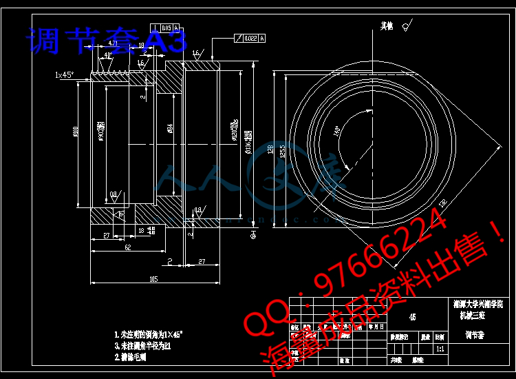
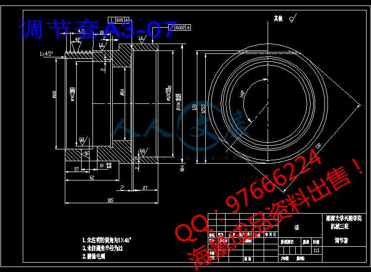
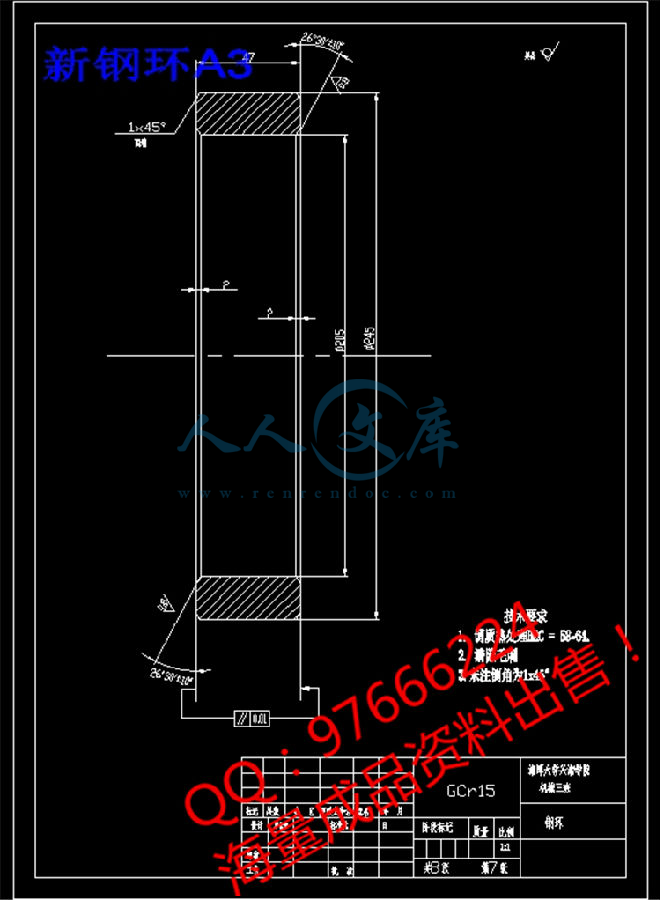
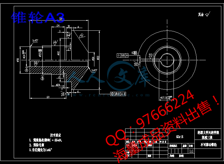
以下为本次文件的目录及部分图纸截图
【需要其他机械类资料可以联系QQ97666224】
目 录
摘要2
Abstract:3
第一章 绪论4
§1.2 机械无级变速器的特征和应用5
§1.3机械无级变速器的选用和润滑密封7
§1.4 本文的主要内容及要求9
第二章摩擦无级变速器的机械特性加压装置和调速机构10
§2.1 机械特性10
§2.2 调速操纵机构11
§2.3 加压装置12
第三章摩擦式无级变速器设计说明和计算过程13
§3.1 摩擦机械无级变速器的工作原理13
§3.2 摩擦无级变速器的特点14
§3.3 锥轮的设计与计算14
§3.4 钢环的设计与计算18
1、钢环尺寸和参数的确定18
2、强度验算21
§3.5 轴系的设计21
§3.6 轴的结构设计22
第四章 主要零件的校核24
§4.1 .输出,输入轴的校核24
§4.2 . 轴承的校核25
总 结26
致 谢27
参考文献资料28
附 录: 文献翻译………………………………………………………29
摩擦式机械无级变速器结构设计
摘要
在某种控制的作用下,使机器的输出轴转速可在两个极值范围内连续变化的无级变速器传动随着机械、材质及加工工艺的高速发展和其需求量日益增多而得到广泛应用和发展。无级变速器的主动和从动两根轴通过传递转矩的中间介质(机械构件、流体、电磁流等)把两根轴直接或间接地联系起来并传递动力。当对主、从动轴的联系关系进行控制时,则两轴间的传动比发生变化(在两极值范围内连续而任意地变化)。用机械构件作为中间介质的为机械无级变速器,其包括摩擦式和脉动式。无级变速器与定传动比传动及有级变速传动(它只有有限的几种传动比)相比,其优点是能够根据工作需要在一定范围内连续变换速度,以适应输出转速和外界负载变化的要求,摩擦式机械无级变速器依靠传动元件之间的摩擦进行传动,钢材材质、加工工艺水平和润滑油料品质等因素是摩擦式机械式无级变速器不断发展的重要保证。本文通过查阅相关的诸多文献和书籍手册等进行钢环式无级变速器原理及其结构、变速原理的传动结构的实现的研究,并对摩擦式机械无级变速器进行结构设计,可直接作为设计文件或指导文件进行生产加工。
关键词:无级变速器;摩擦式;传动;润滑;


- 内容简介:
-
Vibration Control of RelativeTool-Spindle Displacement forComputer Numerically ControlledLathe With Pipe Frame StructureYoshitaka MorimotoMem. ASMEProfessorDirector of Advanced Materials ProcessingResearch Laboratory,Kanazawa Institute of Technology,3-1 Yatsukaho, Hakusan,Ishikawa 924-0838, Japan;e-mail: mosandb1neptune.kanazawa-it.ac.jpNaohiko SuzukiTakamatsu Machinery Co., Ltd.,3-1 Asahigaoka, Hakusan,Ishikawa 924-8558, Japane-mail: suzukitakamaz.co.jpYoshiyuki KanekoTakamatsu Machinery Co., Ltd.,3-1 Asahigaoka, Hakusan,Ishikawa 924-8558, Japane-mail: kanekotakamaz.co.jpMinoru IsobeTakamatsu Machinery Co., Ltd.,3-1 Asahigaoka, Hakusan,Ishikawa 924-8558, Japane-mail: kanekotakamaz.co.jpA new computer numerically controlled (CNC) lathe with a pipeframe bed has been developed. This structure is expected to haveenough space between the truss bars to solve the space problemand have enough rigidity for machine tools. Therefore, a CNClathe whose frame consists of pipes, joints, and diagonal braceshas been developed with enough rigidity and space utility for chipevacuation. From the viewpoint of machine tool usage, real-timevibration control theory is applied to control the relative displace-ment between the tool post and the spindle to suppress specificrelative vibration modes. DOI: 10.1115/1.4027594IntroductionConventional beds or frames for machine tools generally con-sist of cast iron or welded steel plates. These structures are suita-blefromtheviewpointofthemachinetoolsdynamiccharacteristics. Although the demand for downsizing machinetools (such as in desktop machines) is increasing, there is a strictvolumetric limitation to obtain enough space for sufficient chipevacuation. In this case, there are problems of heat conductionand heat transfer. To solve these problems, we propose a tradi-tional but new frame structure for machine tools that consists ofpipes and connecting parts. We looked at the flexibility of theframe design using a pipe frame structure. The frame structurecan be arranged with standardized pipe (diameter and length) anda connecting block. In the case of a lathe, this structure allows fora change in size based on the spindle unit and X-axis table, whichare designed as standardized units.For developing a CNC lathe using this structure 1, the follow-ing problems are assumed:(1) structural vibration generated by the spindle motor unbal-ance and the cutting force disturbance,(2) thermal deformation due to the low heat capacity,(3) insufficient rigidity between the spindle and the X- and Zaxis tables.In this report, we focus on the vibration problem. There havebeen several prior studies 27 on the applications of vibrationcontrol for machine tools. In these research papers, the controlmethods have been applied to the tool post of the lathe machine.These results demonstrated the superiority of vibration control ofthe tool post displacement but do not consider the structural vibra-tion modes that appear in the low-frequency range compared withthe local vibration modes, such as the boring bar and tool post.Developed CNC LatheA unique CNC lathe has been developed based on the idea of apipe frame structure. The specifications are shown in Table 1, anda schematic view is shown in Fig. 1.A maximum spindle speed of 10,000min?1can be obtained.The smallest resolution for the X and Z axes is set to 0.1lm. Thelathe weighs only 525kg (including the covers) and fits within aspace of 440 W?1450 L?1050 H mm3, which is sufficientlycompact. The CNC controller (Mitsubishi Electric Co., Ltd.,M700V) is set beside the machine body.Vibration Control MethodThe most important vibratory motion for the CNC lathe is therelative displacement between the spindle and the tool post. Themachined workpiece is often influenced by the antiphase motionbetween the spindle and the tool; this motion is generated by theresonant frequency. In this case, the antiphase motion is the mostimportant behavior for the workpieces geometric error. Thismotion can be evaluated by measuring the relative vibrationbetween the spindle and the tool. Although this displacementshould be measured directly by a displacement sensor during cut-ting, it is very difficult to position the sensor because of the spaceconstraints, coolant, and chips. Figure 2 shows the typical compli-ance transfer function between the spindle head and the represen-tative frame-connected block. There are several peaks. When wetry to apply vibration control using this data, the control point ishardly determined. Then, two small acceleration sensors are usedto detect the relative vibration mode. One is set on the spindle unitcase and is measured as the signal xs; the other is set on the toolpost of the X-axis table and is measured as the signal xt.The relative vibration x is expressed as follows: x xs? xt(1)Then, the difference between the two acceleration sensor meas-urements in Eq. (1) is calculated and used to extract the antiphasemotion between them. The result of the calculated transfer func-tion is shown in Fig. 3. A frequency peak at 45 Hz can beobserved, and it can be considered a simple one-degree-of-free-dom system. We can use this differential signal as the output ofthe vibration response.Then, modal analysis can be used to obtain the vibration modes,to decide the target vibration mode, and to determine where to setthe actuator for the vibration control. The synthesized mode shapevector at 45Hz is shown in Fig. 4. The antiphase mode betweenthe spindle and the tool post is actually seen from the vectorContributed by the Manufacturing Engineering Division of ASME for publicationin the JOURNAL OFMANUFACTURINGSCIENCE ANDENGINEERING. Manuscript receivedFebruary 20, 2013; final manuscript received April 11, 2014; published online May21, 2014. Assoc. Editor: Tony Schmitz.Journal of Manufacturing Science and EngineeringAUGUST 2014, Vol. 136 / 044502-1CopyrightVC2014 by ASMEDownloaded From: / on 05/26/2014 Terms of Use: /termsfigure. The mode vectors at the head stock for the spindle ( andfi) are so small that the ends of the two actuators can be set atthese points. Based on this result, the other ends of the actuatorsare set on connecting blocks below the X-axis table to control theantiphase vibration mode, as shown in Fig. 1. These two actuatorsgenerate the control forces to suppress the vibratory motion by theactive vibration control method.The relative displacement, velocity, and acceleration aredefined as x, _ x, and x, respectively. Assuming that xdand _ xddenote the desired relative displacement and the relative velocity,the relative displacement and the relative velocity are defined asxd? x;_ xd? _ xThe controlled force can be expressed as follows:Kv_ xd? _ x Kdxd? x(2)where the weight coefficients Kdand Kvare used. The equation ofmotion is described as follows when a harmonic force faejxtactson this system:m x c_ x kx faejxt Kv_ xd? _ x Kdxd? x(3)Because the desired relative displacement xdand relativevelocity _ xdare to be zero, Eq. (3) is described as follows:m x c Kv_ x k Kdx faejxt(4)In Eq. (2), substituting f faejxt, the following equation can bederived: x_ x? ?c=m?k=m10?_ x x? ?1=m0?f(5)This equation of motion is rewritten as the following stateequation:_X AX BF(6)In the case of applying a control force that is proportional to thestate vector X, the control force is described as F ?KX. Then,substituting this into Eq. (6), the following state equation is obtained:_X A ? BKX(7)Once this equation can be obtained, the only thing to dois calculate the feedback gain K usingMATLAB(MathWorksMATLABand Simulink). To calculate this coefficient K, the modalparameters m, c, and k must first be determined. We calculatedthese values using the simple “mass response method” becausethe vibratory motion can be assumed to be one-degree-of-freedomfrom the result in Fig. 3. Once the known mass is set on the toolFig. 1Schematic view of developed CNC latheFig. 2Typical measurement result of compliance transferfunction by conventional impulse excitation method on a repre-sentative pointFig. 3Transfer function between input force and relative dis-placement (tool post and spindle)Fig. 4Mode shape vector (top view)Table 2Identified modal parameterItemsValueUnitMass, m214kgDamping factor, c8.01N/(m/s)Spring constant, k1.62?1007N/mKv3.66?1003N/m/sKd5.73?1002N/(m/s)Table 1Specifications of CNC latheItemsSpecificationsHead stockChuckCollet chuckMaximum speed10000min?1Tool post typeHorizontal linearMinimum resolution0.0001mmSize440 W?1450 L?1050 H mmMachine weight525kgCNC controllerMitsubishi Electric Co., Ltd. M700V044502-2 / Vol. 136, AUGUST 2014Transactions of the ASMEDownloaded From: / on 05/26/2014 Terms of Use: /termspost, the change in the resonant frequency is measured, and themodal parameters are obtained, as shown in Table 2. These aresubstituted into Eq. (7), and the feedback gain K is calculatedaccording to linear-quadratic (LQ) control theory.Vibration Control SystemLead zirconate titanate (PZT) devices are used in the vibrationcontrol system as the actuator source. Structural vibration controland motion control for machine tools use this device because ofits large generated force and high-frequency response 811.We developed an actuator that consists of a PZT, a fluid cham-ber with two different cross-sectional areas, and connecting rods,as shown in Fig. 5. The fluid chamber is used to transform thegenerated force from the PZT. Although the longitudinal displace-ment of the PZT is short enough, the displacement is reduced bythe chamber area. This effect makes the generated displacementless than a submicron order. Two actuators are set between theconnecting blocks as brace bars. The dynamic characteristics areevaluated using the impulse response method, and the result isshown in Fig. 6. This actuator can be used below 200Hz. Theeffects of the vibration control are evaluated in Effects of ActiveVibration Control section. Although the thermal elongation of thebrace bars has to be considered when the long run operation, wedo not consider the thermal deformation of the frame because ofthe short-time machining.Effects of Active Vibration ControlThe relative vibration between the spindle and the tool post iscontrolled by two actuators. In this case, according to LQ controltheory, we have developed the control system to realize thecontrol method represented by the block diagram in Fig. 7 and inTable 3. This system runs with a sampling speed of 3000Hz. Therelative vibration is generated by the unbalance of the spindleunit. Since the maximum displacement is observed at around2725min?1(45.4Hz), the target frequency is set to 45 Hz.The experimental procedure has been executed during air cut-ting and during cutting. From the experimental result and fre-quency response of the actuator, the target-controlled frequencyrange is set from 10 to 100Hz. A band-pass real-time filter isadapted to obtain the vibration signal and to suppress the disturb-ance noise and high-frequency signals.To evaluate the effect of the active vibration control, two accel-eration sensors due to the limitation of the installation space areused for the control. The relative vibration is numerically inte-grated to obtain the relative velocity and the relative displace-ment. The relative displacement itself during motion is measuredby a laser displacement sensor that is set on the tool post anddetects the relative displacement of the spindle unit.The control result during finish cutting is shown in Fig. 8. Thecontrol parameters have been determined previously during aircutting. This condition is not always applicable to the conditionduring cutting because the workpiece and the tool contact eachother, and the cutting force acts on the contact point. Although themodal parameters are not always constant, our control system isapplied using the same conditions as air cutting, and the effect ofthe vibration control is evaluated during cutting.When the control is started, the relative displacement decreasesits amplitude. FFT analysis is used to determine the difference inthe frequency element between with control and without control,as shown in Fig. 9. The solid line shows the result with control,and the dotted line shows the result without control. Almost 50%of the vibration amplitude around the target frequency of 45 Hz issuppressed by our developed system. The effect of an increase inrigidity by the actuator installed as a brace can be seen in thelower frequency range. On the other hand, the effect above100Hz cannot be seen because of the filter effect of the controlFig. 5Schematic diagram of PZTactuator for vibration controlFig. 6Transfer function between input voltage of actuator andtable displacement by impulse responseFig. 7Block diagram for vibration controlTable 3Experimental setup for vibration controlItemsValueUnitSpindle speed2700min?1Target frequency45HzSampling frequency3000HzDepth of cut0.1MmFeed0.02mm/revWorkpiece materialC3604BDFig. 8Comparison of relative motion during cuttingJournal of Manufacturing Science and EngineeringAUGUST 2014, Vol. 136 / 044502-3Downloaded From: / on 05/26/2014 Terms of Use: /termssystem. These results demonstrate that this vibration control sys-tem used during finish cutting is suitable for our pipe frame CNClathe. To improve the effect of the vibration control, the layout(including the direction of the actuator) should be considered, andfurther improvement of this actuator system is needed to suppressthe vibration amplitude more efficiently.Evaluation of Workpiece by Vibration ControlSince it has been confirmed that the vibration control is effec-tive even during cutting, we evaluated the accuracy of themachined workpiece. Because the target control frequency wasset to 45 Hz, the effect of the control result appears as surfacewaviness. Then, the surface profile was measured by the surfaceroughness tester without a high-pass filter. Figure 10 shows themeasured results. The upper figure shows the profile withoutvibration control, and the lower figure shows the result with vibra-tion control. The surface waviness is remarkably improved. Theimprovement of the waviness at this frequency range is related tothe relative vibration mode that appears in this frequency range.Figure 11 shows the harmonic analysis of the measured round-ness result. Since the target frequency is set to the spindle rota-tional frequency, the effect of the vibration control generallyappears on the roundness with two undulations per round. Themeasured result shows this tendency well. The amplitude of theundulations per round decreased by 50% from the amplitude with-out control.These results show the effectiveness of our control system atsuppressing the relative vibration mode between the spindle andthe tool post and the improvement in the accuracy of the machinedworkpiece.ConclusionsIn this paper, the effectiveness of the real-time vibration controlfor the developed CNC lathe by a single degrees of freedommodel has been evaluated using the differential signal between thespindle and the tool post. The main results obtained as follows:(1) Almost 50% of the vibration amplitude around the targetfrequency of 45 Hz is suppressed by our developed system.(2) The roundness amplitude of the undulations per rounddecreased by 50% from the amplitude without control.(3) Results obtained show the effectiveness of the applied con-trol system at suppressing the relative vibration modebetween the spindle and the tool post.Further investigations are required to improve the vibrationcontrol system, including the layout (the direction of the actuator)and actuator performance to suppress the vibration amplitudemore efficiently.AcknowledgmentThe authors express their gratitude for the assistance of Kazu-hiro Shimizu, who has supported our experiments. This study waspartially supported by grant funding from the New Energy andIndustrial Technology Development Organization.References1 Suzuki, N., 2010, “Development of Ultra Small Size CNC Lathe by Pipe FrameStructure,” Proceedings of 4th CIRP International Conference on High Per-formance Cutting, Nagoya, Japan, Vol. 2, p. 183.2 Claesson, I., 1998, “Adaptive Active Control of Machine-Tool Vibration in aLathe,” Int. J. Acoust. Vib., 3(4), pp. 155162.3 Choudhury, S. K., 1997, “On-Line Control of Machine Tool Vibration in Turn-ing,” Int. J
- 温馨提示:
1: 本站所有资源如无特殊说明,都需要本地电脑安装OFFICE2007和PDF阅读器。图纸软件为CAD,CAXA,PROE,UG,SolidWorks等.压缩文件请下载最新的WinRAR软件解压。
2: 本站的文档不包含任何第三方提供的附件图纸等,如果需要附件,请联系上传者。文件的所有权益归上传用户所有。
3.本站RAR压缩包中若带图纸,网页内容里面会有图纸预览,若没有图纸预览就没有图纸。
4. 未经权益所有人同意不得将文件中的内容挪作商业或盈利用途。
5. 人人文库网仅提供信息存储空间,仅对用户上传内容的表现方式做保护处理,对用户上传分享的文档内容本身不做任何修改或编辑,并不能对任何下载内容负责。
6. 下载文件中如有侵权或不适当内容,请与我们联系,我们立即纠正。
7. 本站不保证下载资源的准确性、安全性和完整性, 同时也不承担用户因使用这些下载资源对自己和他人造成任何形式的伤害或损失。

人人文库网所有资源均是用户自行上传分享,仅供网友学习交流,未经上传用户书面授权,请勿作他用。
 川公网安备: 51019002004831号