外文翻译.doc

液压卡盘设计【优秀含26张CAD图纸+液压设备全套课程毕业设计】

收藏

资源目录
跳过导航链接。
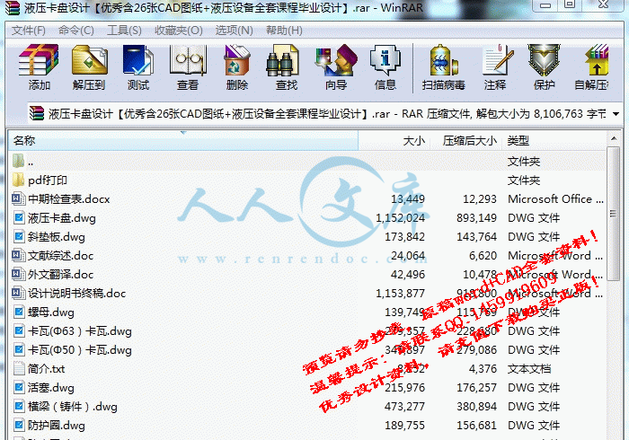
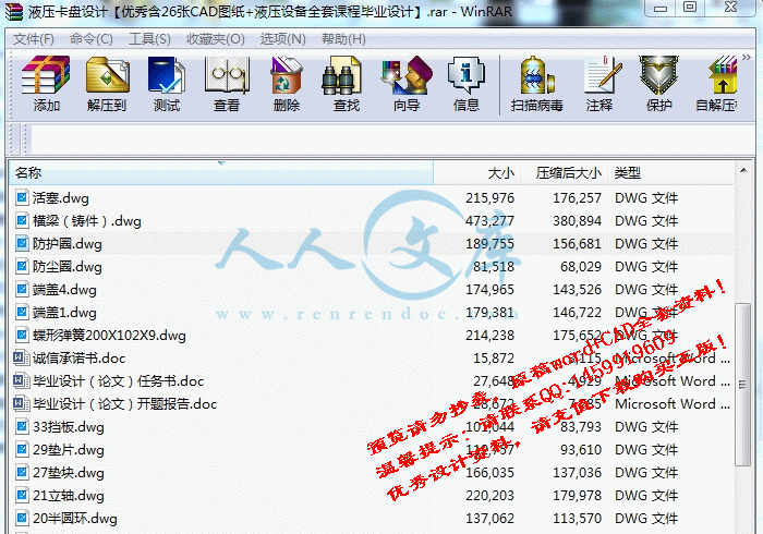
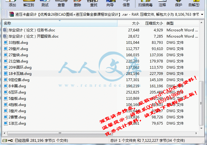
液压卡盘设计【优秀含26张CAD图纸+液压设备全套课程毕业设计】.rar
诚信承诺书.doc---(点击预览)
设计说明书终稿.doc---(点击预览)
简介.txt---(点击预览)
毕业设计(论文)开题报告.doc---(点击预览)
毕业设计(论文)任务书.doc---(点击预览)
文献综述.doc---(点击预览)
外文翻译.doc---(点击预览)
中期检查表.docx---(点击预览)
pdf打印
18卡瓦轴.dwg
1法兰.dwg
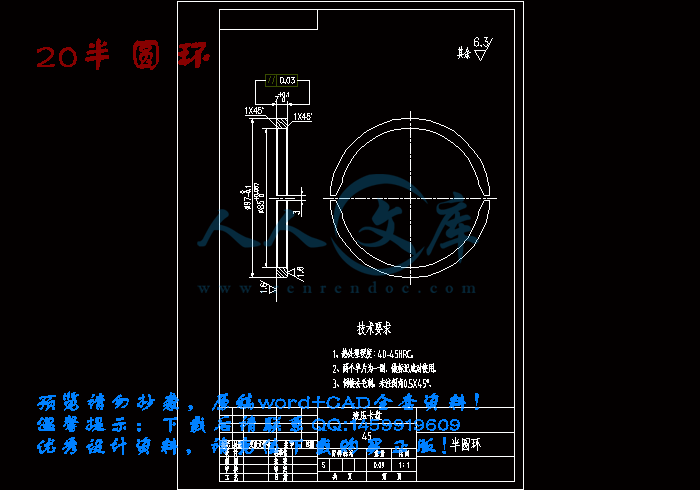
20半圆环.dwg
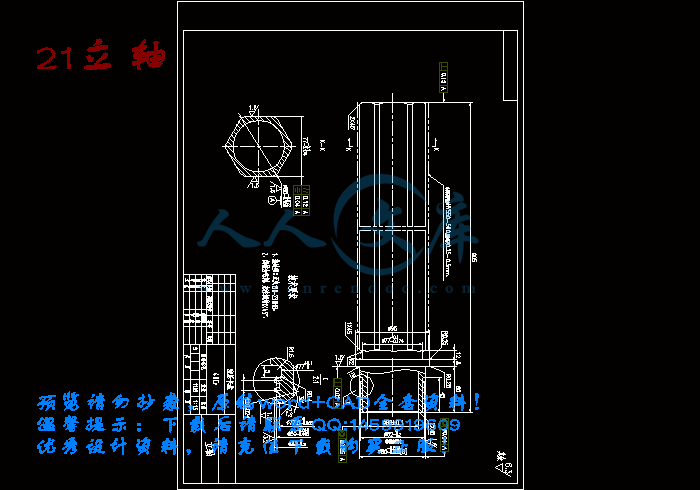
21立轴.dwg
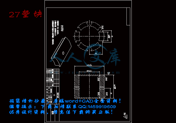
27垫块.dwg
29垫片.dwg
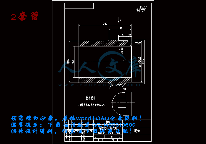
2套管.dwg
33挡板.dwg
3垫片.dwg
4挡板.dwg
5垫板.dwg
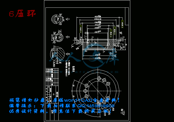
6压环.dwg
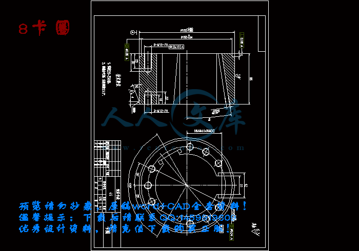
8卡圈.dwg
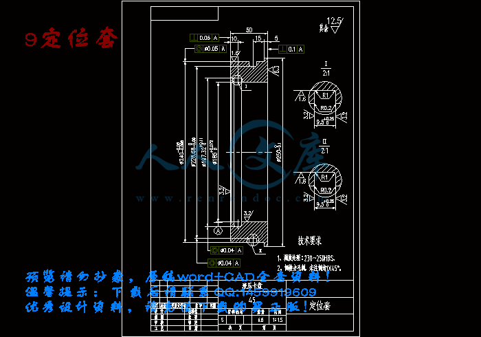
9定位套.dwg
卡瓦(Φ50)卡瓦.dwg
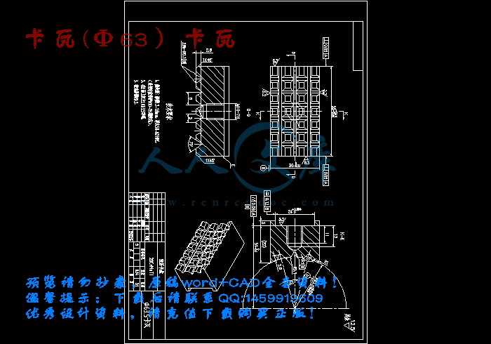
卡瓦(Φ63)卡瓦.dwg
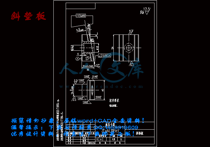
斜垫板.dwg
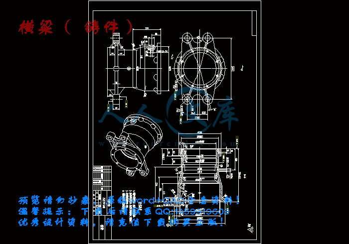
横梁(铸件).dwg
活塞.dwg
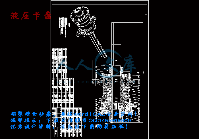
液压卡盘.dwg
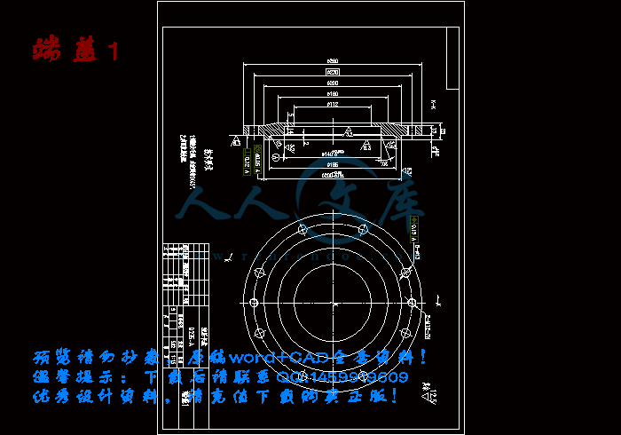
端盖1.dwg
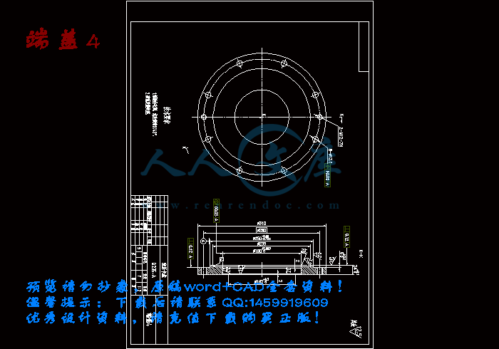
端盖4.dwg
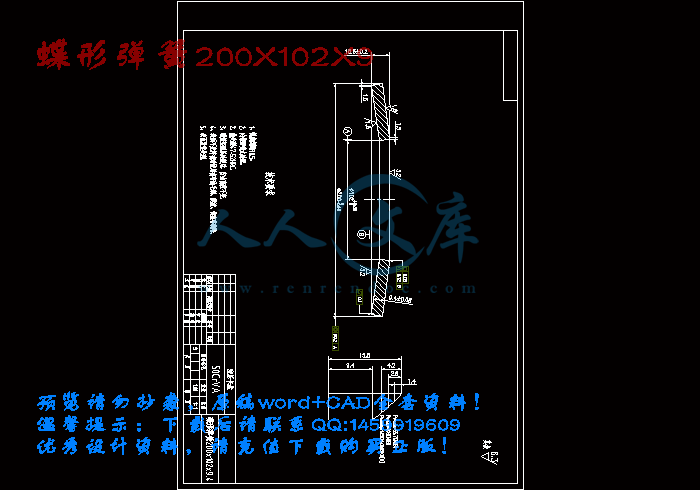
蝶形弹簧200X102X9.dwg
螺母.dwg
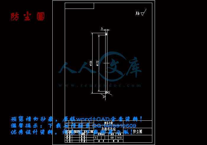
防尘圈.dwg
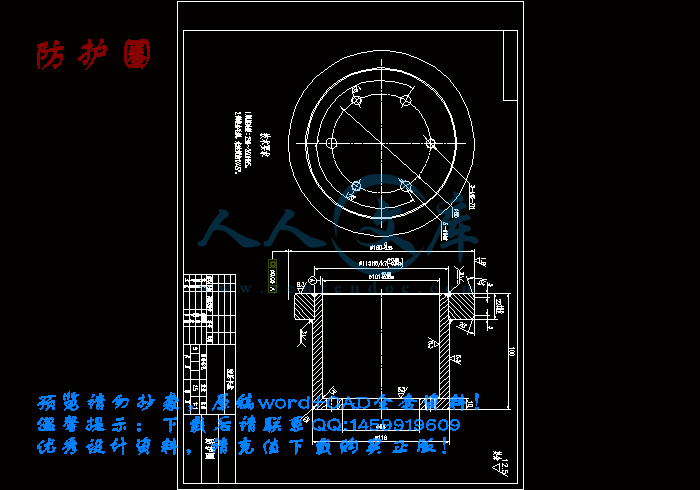
防护圈.dwg
压缩包内文档预览:
预览图 预览图 预览图 预览图 预览图 预览图
编号:458911    类型:共享资源    大小:6.21MB    格式:RAR    上传时间:2015-07-21 上传人:QQ14****9609 IP属地:陕西
50
积分
关 键 词:
液压卡盘 机械设计 毕业设计 液压卡盘设计 液压设备全套课程毕业设计
资源描述:

液压卡盘设计【优秀含26张CAD图纸+液压设备全套课程毕业设计】

【带任务书+开题报告+中期检查表+文献综述+外文翻译】【24页@正文9600字】【详情如下】【需要咨询购买全套设计请加QQ1459919609 】

18卡瓦轴.dwg

1法兰.dwg

20半圆环.dwg

21立轴.dwg

27垫块.dwg

29垫片.dwg

2套管.dwg

33挡板.dwg

3垫片.dwg

4挡板.dwg

5垫板.dwg

6压环.dwg

8卡圈.dwg

9定位套.dwg

pdf打印

中期检查表.docx

卡瓦(Φ50)卡瓦.dwg

卡瓦(Φ63)卡瓦.dwg

外文翻译.doc

文献综述.doc

斜垫板.dwg

横梁(铸件).dwg

毕业设计(论文)任务书.doc

毕业设计(论文)开题报告.doc

活塞.dwg

液压卡盘.dwg

端盖1.dwg

端盖4.dwg

蝶形弹簧200X102X9.dwg

螺母.dwg

设计说明书终稿.doc

诚信承诺书.doc

防尘圈.dwg

防护圈.dwg

任务书

毕业设计(论文)题目          液压卡盘设计

毕业设计(论文)主要内容和要求:

内容:

 1.了解卡盘的特点,基本结构及原理。

2.分析卡盘受力,运作方式。

3.液压系统的设计。

4.主要参数确定与结构计算。

要求:

1、查阅相关资料,确定总体设计方案???

2、根据总体布局,计算受力,绘制卡盘???

3、完成卡盘总体设计????

4、撰写设计说明书?

5、翻译外文技术资料

毕业设计(论文)主要参考资料:

[1]机械设计(第九版) 李建功主编,机械工业出版社,2007

[2]材料力学(第五版) 刘鸿文主编,高等教育出版社,2004

[3]理论力学(第七版) 哈尔滨工业大学理论力学教研室,2002

[4]机械制图(第二版)郭克希,王建国主编,机械工业出版社,2009

[5]液压去气压传动 桂兴春,林艾光主编,北京航空航天大学出版社,2011

[6]互换性与技术测量 付求涯,邱小童主编,北京航空航天大学出版社,2011

毕业设计(论文)应完成的主要工作:

1、查阅、收集资料,熟悉有关的资料,学习相关的知识。结合毕业设计课题进行外文资料阅读并翻译外文资料。

2、熟悉设计任务,提出初步的设计方案,并征求指导教师的意见。拟定总体方案,绘出系统图,定出相关参数,并绘出总体草图。

3、对草图进行修改,并完成开题报告。整理资料,编写设计说明书。

4、利用中国知网、维普、万方等数据库完成与毕业论文相关内容的论文检索。

毕业设计(论文)进度安排:

序号毕业设计(论文)各阶段内容时间安排备注

1查阅、收集资料,熟悉有关的资料,学习相关的知识。2014.12

2结合毕业设计课题进行外文资料阅读并翻译外文资料。2014.12

3开始编写毕业设计工作计划。2015.1

4熟悉设计任务,提出初步的设计方案,并征求指导教师的意见。2015.2

5拟定总体方案,绘出系统图,定出相关参数,并绘出总体草图。2015.3

6对草图进行修改,并完成开题报告。2015.3

7整理资料,编写设计说明书。2015.4.1

液压卡盘设计

摘要

钻探在国民经济的发展中发挥着至关重要的作用,随着石油勘探开发力度的增加,石油钻井机械的自动化、智能化程度也在不断提高。液压卡盘是钻机的一个主要部件,其功能是夹紧钻机上的钻杆,并向钻杆传递转矩和轴向力,驱动钻具实现回转和给进,完成加减压钻井。

本文研究了液压卡盘的设计,首先完成了卡盘的结构方案设计,选择了液压式卡盘,分析了液压卡盘的工作原理及制造要求。文中对液压卡盘的各项参数进行了详细设计了液压卡盘承载力、卡瓦对钻杆的夹紧力以及蝶形弹簧的轴向推力。文中还计算了活塞的行程S,夹紧包角,以及蝶簧夹紧力、卡盘松开油压力等参数,最后完成了卡盘结构装配图及主要零件图的设计,并对液压控制系统进行了简要设计。本文可以为卡盘的相关设计提供参考。

关键词:液压卡盘; 钻杆; 受力分析; 液压控制

Abstract

Drilling plays a very important role in the development of national economy, along with the increase of oil exploration and development efforts, automation, intelligent level of petroleum drilling machine has been improved. Hydraulic chuck is one of the main components of drilling rig, its function is to drill pipe clamp drill, and transfer torque and axial force to the drill pipe, drill rotary and feed drive, complete decompression drilling.

This paper studies the design of hydraulic chuck, the structure design of the hydraulic chuck, chuck, analyzes the working principle and manufacturing requirements of hydraulic chuck. The parameters of hydraulic chuck, in this paper, the detailed design of the hydraulic chuck clamping force on the bearing capacity, the slip of drill pipe and the axial thrust of the butterfly spring. This paper also calculated the stroke of the piston S, clamping angle, as well as the butterfly spring chuck clamping force, loosen the oil pressure and other parameters, and finally completed the design of the assembly structure and the main parts of the map the chuck, and the hydraulic control system has carried on the brief design. This paper can provide a reference for the design of the chuck.

Keywords: hydraulic chuck;  drill pipe;  stress analysis;  hydraulic control

目  录

1绪论1

1.1发展背景1

2卡盘结构方案设计3

2.1 机械式卡盘3

2.1.1机械式卡盘结构设计3

2.1.2 机械式卡盘工作原理4

2.2液压式卡盘5

2.2.1 液压卡盘的总体设计要求5

2.2.2液压式卡盘的结构设计5

2.2.3 液压卡盘的工作原理6

2.2.4 液压卡盘的制造要求6

3主要参数设计6

3.1液压卡盘承载力的确定6

3.2 卡瓦对钻杆的夹紧力计算7

3.3 蝶形弹簧的轴向推力的计算7

3.4 设计蝶形弹簧9

3.5 活塞行程S 的确定11

3.6夹紧包角13

3.7蝶簧夹紧力13

3.8卡盘松开油压14

4.液压卡盘装配图及部分零件图15

5.液压控制系统的设计18

6.结论18

参考文献19

致谢20

1绪论

1.1发展背景

钻探在国民经济的发展中发挥着至关重要的作用,其中尤以在石油天然气开采领域中的发挥着最为关键的核心功能。石油天然气具有特殊的形成条件,具有其它能源所没有的特性,由此也就决定了其采集作业方式的独特性。从发现油气资源至今,石油的主要采集方式是钻井开采。由古代的手工开凿到现代的机械化钻探,钻井工具和钻井方式发生了根本性的变化。随着工业化技术的发展,钻井技术也将发生更大的改变。在现代工业自动化发展的进程中,石油设备的自动化程度也在不断提高,工业机器人作为现代化生产的重要自动化设备也在逐步引入到石油生产中去。传统的石油开采过程中,大量工作由工人人力进行操作,而野外艰苦的工作环境和笨重的钻采设备,使石油生产变得艰苦而危险。 随着石油勘探开发力度的增加,石油钻井机械的自动化、智能化程度也在不断提高。

自动化钻井是国外在 20 世纪 90 年代发展起来的一项前沿钻井技术,是21 世纪钻井技术的主要发展方向。自动化钻井主要包括井下闭环钻井技术,地面钻机的自动化,钻井泥、液浆等钻材的装卸、配制和泵送自动化,钻井专家系统四个方面。地面钻机的自动化,即钻井地面作业的自动化操作,钻杆处理系统是其中非常重要的部分。钻杆自动排放系统是钻管处理系统的关键组成部分,是伴随着钻井自动化技术的发展而产生的。机械化减轻了钻井工人的体力劳动,改变传统的提升卡瓦和人工钻杆处理装置,有力地扩大了钻井工人的安全工作范围,使他们由劳动者变为操作者。

半自动化系统利用信息技术和智能控制系统改变现有的管子处理系统,在新的系统中可减少操作者的数量。随着海洋深水钻井的开展,现在作业水深已达到 7000至10000英尺;陆地钻机也由老旧的5000米钻机向15000米钻机发展。影响钻井时间增加的内在因素不仅仅是起下钻作业,钻杆、套管和隔水管的搬运和排放也严重影响着钻井计划。在钻井的同时离线接立根、自动传送和排放钻杆等操作将会大大节省钻井时间。钻杆处理系统正在成为自动化,模块化钻井设备设计的工业标准。

在这个大背景下,钻杆自动传输机构也应运而生,从手动钢丝旋扣拉锁、起吊绞车、提升卡瓦等发展到现在最先进的钻杆自动传输系统,从简单的手动设备发展到了现代化的工业机器人。

参考文献

[1]  冯德强. 钻机设计. 北京: 中国地质大学出版社,1993

[2]  黄镊恺、郑文纬主编.《机械原理》(修订版),人民教育出版,1981

[3]  David,Reid,Varco international,Inc. The Development of Automated Drilling Rigs,2007

[4]  刘文庆,崔学政,张富强.  钻杆自动排放系统的发展及典型结构[J].石油矿场机械,2007,36(11):74-77

[5] Gluch, David P. Automation. An Evolution in Drilling Technology[J]. Drilling, 1986,24-30

[6] Gadbois, J. F.and Turner, J. W.. Discoverer II Outperforms Expectations[R]. Houstion: American Assn. of Oilwell Drilling Contractors Meeting, 1968

[7] Besijn, H.: Pipe Handling System[R].The Hague. AIME meeting,1974

[8] 刘文庆.  钻井平台钻杆自动排放系统研究:[中国石油大学硕士学位论文].青岛:中国石油大学(华东),2008,3-4

[9]  Brugman J.D.: Automated Pipe Handling. Fresh Approach[R].New Orleans: PE/IADC Drilling Conference,1987

[10] Kinzel, Holger and Lorenz, Joerg. A New Approach to Mechanized Tubular Handling and Running as a Safe and Cost Effective Alternative[R]. Amsterdam: SPE/IADC Drilling Conference,1997.

[11] 姜鸣,曹言悌,周声强.陆地钻机钻杆自动排放系统的设计方案[J].石油机械,2008,36(8):95-98

[12] 尹晓丽,刘文杰,张中慧.钻杆自动传送系统及设计方案[J].石油矿场机械, 2009,38(7):42-4

[13] 刘文庆.  钻井平台钻杆自动排放系统研究:[中国石油大学硕士学位论文].青岛:中国石油大学(华东),2008,16

[14] 陈如恒,沈家骏.  钻井机械的设计计算.  石油工业出版社,1995,263-313

[15] 成大先,主编.  机械设计手册.第 2 卷(第 5 版).化学工业出版社,2007


内容简介:
中国地质大学长城学院 本科毕业论文外文资料翻译 系 别 : 工程技术系 专 业 : 机械设计制造及其自动化 姓 名 : 王鹏飞 学 号 : 05211502 2015 年 4 月 28 日 nts中国地质大学长城学院 2015 届毕业设计外文翻译 1 外文资料翻译译文 液压卡盘的设计方法 1.动机和目标 卡盘设计是连接设计与制造间的一项重要任务。自动化卡盘设计和计算 机辅助卡盘设计开发(卡盘 CAD)是下一代制造系统成功实现目标的关键。在这片论文里,讨论了一种卡盘设计的方法,这种方法有利于在目前环境下卡盘设计的自动化。 卡盘设计方法的研究已成为国内多家科研工作的重点。作者:周在对工件的稳定和总需求约束了双重标准,突出重点的工作。在卡盘设计中广泛的运用了人工智能( AI)以及专家系统。部分 CAD 模型几何信息也被用于卡盘设计。 Bidanda 描述了一个基于规则的专家系统,以确定回转体零件的定位和夹紧。夹紧机制同时用于执行定位和夹紧功能。 DeVor分析了切削力钻井机械和建筑模型及 其他金属切削加工。康有为在中定义了装配约束建模的模块化与卡盘元件之间的空间关系。一些研究人员采用模块化卡盘设计原则。另一些卡盘设计工作者已经做了报告,可以找到卡盘设计相关的大量的审查工作。 2.卡盘设计的整体方法 在本节中,描述了整体夹紧的设计方法。通常对较理想的位置的那一部分进行夹紧,并减低切削力的影响。夹紧的位置和卡盘设计中定位的位置是高度相关的。通常,夹紧和定位可以通过同样的方法来完成。但是,不明白这两个是卡盘设计中不同的方面,可能导致卡盘设计的失败。多数人的在规划过程中首先解决定位问题,这样可以使开 发的定位与设计的定位相契合。不过,整体定位及设计方法不在本文讨论范文内。 除了零件的设计(为此卡盘设计有待开发),公差规格,过程序列,定位点和设计等因素外,还应投入 CAD 模型到卡盘设计方法中。这样的卡盘可以夹紧并支撑定位器。指导使用的主要内容应尽量不抵制切割或加工过程和中所涉及的操作。相反,应定位卡盘,使切削力在正确的方向,这将有助于保持在一个特定的部分加工操作安全。通过引导对定位器的切割力量,部分(或工件)被固定,固定定位点,因此不能移动的定位器。 在这里讨论的卡盘的设计方法必须在整体卡盘设计方法的范围内 。在此之前进行定位器 /支撑和卡盘设计的初步阶段,涉及到的分析和识别的功能、相关的公差和其他规范是必要的。根据初步的评估和测定,定位 /支撑设计与卡盘设计结果的在此基础上可以同时进行。本文对所描述卡盘设计的方法讨论基于定位器 /支撑设计与先前已经确定的假设(包括适当的定位和支持测定一个工件的定位,以及识别和卡盘,如 V 元素的支持面块,基础板,定位销等)。 2.1 卡盘设计的输入 nts中国地质大学长城学院 2015 届毕业设计外文翻译 2 输入包括对特定产品的设计翼边模型,公差信息,提取的特征,过程顺序和部分在给定的每一个设计的相关特性的加工方向,面向的位置和定位装置,以及加工过程中的各种工序,须出示每个相应的功能。 2.2 卡盘设计的方法 具体步骤概述如下: 第 1 步:设置配置清单以及相关的 进程 _功能 条目。 第 2 步:确定方向和夹紧力。输入必要的加工方向向量 mdv1, mdv2 mdvn,面对nvs 的支持力,并确定法向量。如果加工方向向下(对应的方向向量 0, 0, -1),和面的支持向量平行于加工方向,那么,夹紧力方向平行向下加工方向 0, 0, -1。如果必需要侧面夹紧并没有可夹紧的地方,那么在其中放置一个卡盘夹 紧下调,然后边钳方向计算如下。让 sv 和 tv 辅助常规的向量代替次要的和三级定位孔。然后,使用夹紧机构夹紧一个方向,例如, av 应平行于这两个法向量,即,正常向量应分别与每块表面的 sv 和 tv 向量平行。侧面夹紧面应该是一对分别平行于面 sv 和 tv 的平面孔。 第 3 步:从列表中选出最大有效加工力。这样能够有效的平衡各加工力。 第 4 步:利用计算出的最高有效加工力,才能确定用来支撑工件加工的面积的卡盘尺寸(例如,一个带夹子可以作为一个夹紧机构使用)。 第 5 步:确定给定工件的夹紧面。这一步在第 4 步中所述过。 第 6 步:该卡盘的夹 紧面的实际位置自动在第 5 步中确定。考虑接下来的步骤并返回第一步。 本文所讨论的方法的独特性是零件的夹紧面的几何形状,拓扑和功能发生了被加工为基础的系统鉴定。其他方法都没有利用了定位器的位置,该方法使用定位器在对持有一级,二级和三级定位器加工的工件。这种方法的另一个好处是在可行的候选面上确定在面上用卡盘面交点测试(如前所述),并迅速和有效地确定潜在的下游过程中可能出现问题,夹紧和加工的功能检测。 3.总结 在这篇论文中,对在一个卡盘设计方法的总体框架内进行了卡盘设计方面的讨论。 设计定位器,规范零件设计,和其 他相关被用来确定夹紧面和夹紧方向。并讨论了各种自动化步骤。 液压卡盘的主要设计计算 , 概括起来 ,就 是确定最大载荷 , 根据最大载荷确定夹紧力 ,根据夹紧力 , 计算碟形弹簧的轴向推力 , 并按此轴向推力设计碟形弹簧。碟形弹簧的设计是液压卡盘的设计关键 ,在设计和制造上都不能出现问题 , 否则液压卡盘不可靠 。 该碟形弹簧式液压卡盘零件较少,结构紧凑、简单,更换卡瓦和其他易损件比较方便。与油缸式卡盘结构相比,液压系统比较简单,使用的油管少,工作性能稳定可靠。 nts中国地质大学长城学院 2015 届毕业设计外文翻译 3 外文原文 Design method of hydraulic chuck - An automated design method of the chuck J. Cecil 1.Motivation and goal Chuck design is an important link between design and manufacturing tasks. Automation design and computer aided chuck chuck chuck (CAD) design development is the key to the next generation of manufacturing system to achieve the target. Discussed in this paper, a method of chuck design, this method is beneficial to chuck in the current environment design automation. Chuck design method research has become the focus of the domestic many scientific research work. Author: weeks on the stability of the artifacts and aggregate demand constraint the double standard, focused work. The chuck widely applied in the design of artificial intelligence (AI) and expert system. Part of the CAD model geometry information has also been used in the design of chuck. Bidanda describes a rule-based expert system, to determine the positioning and clamping of axially symmetrical parts. The clamping mechanism is used to perform the positioning and clamping function at the same time. DeVor drilling machinery and construction analysis of the cutting force model and other metal cutting processing. Kang youwei assembly constraints defined in the modeling of modularization and spatial relationship between chuck components. Some researchers used modular chuck design principles. Other chuck design workers have done a report, you can find the chuck design review related to a lot of work. 2.Chuck design of integral method In this section, describes the whole design method of clamping. Usually for that part of the ideal location for clamping, and reduce the influence of cutting force. The position of the clamping and chuck positioning is highly related to the location of the design. Usually, clamping and positioning can be finished by the same method. But, dont understand this is two different aspects in the design of chuck, may lead to the failure of the chuck is designed. Most people in the process of planning the first solve the problem of positioning, so that we can make development positioning and design of positioning. However, the overall positioning and design method is not discussed in this article the idol. nts中国地质大学长城学院 2015 届毕业设计外文翻译 4 In addition to the components of the design (design) should be developed for this chuck, tolerance specifications, process sequence, anchor point and design factors, such as should also be put into CAD model to chuck design method. The chuck can be clamped and supported locator. The main content of the guide to use should try not to boycott the cutting or machining process and involved in the operation. On the contrary, should locate chuck, make cutting force in the right direction, this will help keep safe operation in a specific part of the processing. Cutting force through the guide to the locator, part of (or workpieces) are fixed, fixed anchor point, so cant move the locator. The chuck here to discuss the design method must be within the scope of the overall design method of chuck. Before this locator/support and initial stage of the chuck design involves the analysis and recognition function, related tolerance and other specifications are necessary. According to preliminary assessment and measurement, design and chuck positioning/support design on the basis of the result can be simultaneously. Chuck described in this paper, the design method is discussed based on the locator/support design with previously established assumptions (including the appropriate location and support of a workpiece positioning, as well as identify and chuck, such as V elements support surface of the block, base plate, pins, etc.). 2.1 chuck design input Input including wing side model, the design of a specific product tolerance information, extract the features, process sequence and some related characteristics of each design in a given processing direction, geared to the needs of the location and positioning device, various working procedure, and the process required to present each of the corresponding function. 2.2 chuck design method Specific steps outlined below: Step 1: set up the configuration list and related process _ function entry. Step 2: determine the orientation and clamping force. Input the necessary processing direction vector mdv1 mdv2. MDVN, face upward force NVS, and normal vector were determined. If processing direction downward (corresponding to the direction of the vector 0, 0, 1), and the support vector parallel to the direction of processing, so, clamping force direction parallel processing downward direction 0, 0, 1. If necessary to side clamp is not capable of clamping, then place a chuck clamping down on them, then side clamp direction calculation as follows. Let sv and TV auxiliary conventional vector instead of the secondary and tertiary locating holes. Then, use the clamping mechanism of clamping a direction, for example, av should be parallel to the two normal vector, i.e., the normal vector should be parallel to each sv nts中国地质大学长城学院 2015 届毕业设计外文翻译 5 and TV on the surface of the vector. Side clamping surface should be a pair of parallel to the plane of sv and flat faces of the TV. Step 3: select the maximum effective processing from the list. It can effectively balance the processing power. Step 4: use to calculate the maximum effective processing, can be used to support the area of the workpiece processing chuck size (for example, a belt clip can be used as a fastening device). Step 5: to determine if a given workpiece clamping surface. This step is described in step 4. Step 6: the chuck clamping the actual location automatically determined in step 5. Consider the following steps and returns the first step. Is discussed in this paper, the method of the uniqueness of parts clamping surface geometry, topology and feature the processed on the basis of system identification. Other methods are not using the locator, the method USES the locator to hold level, secondary and tertiary positioner of the workpieces. Another benefit of this approach is determined on the viable candidate in surface intersection test card disk (as mentioned above), and quickly and effectively identify potential problems may occur during the process of downstream, clamping and processing function of detection. 3. Summary In this paper, on the design method of a chuck chuck desig
温馨提示:
1: 本站所有资源如无特殊说明,都需要本地电脑安装OFFICE2007和PDF阅读器。图纸软件为CAD,CAXA,PROE,UG,SolidWorks等.压缩文件请下载最新的WinRAR软件解压。
2: 本站的文档不包含任何第三方提供的附件图纸等,如果需要附件,请联系上传者。文件的所有权益归上传用户所有。
3.本站RAR压缩包中若带图纸,网页内容里面会有图纸预览,若没有图纸预览就没有图纸。
4. 未经权益所有人同意不得将文件中的内容挪作商业或盈利用途。
5. 人人文库网仅提供信息存储空间,仅对用户上传内容的表现方式做保护处理,对用户上传分享的文档内容本身不做任何修改或编辑,并不能对任何下载内容负责。
6. 下载文件中如有侵权或不适当内容,请与我们联系,我们立即纠正。
7. 本站不保证下载资源的准确性、安全性和完整性, 同时也不承担用户因使用这些下载资源对自己和他人造成任何形式的伤害或损失。
提示  人人文库网所有资源均是用户自行上传分享,仅供网友学习交流,未经上传用户书面授权,请勿作他用。
关于本文
本文标题:液压卡盘设计【优秀含26张CAD图纸+液压设备全套课程毕业设计】
链接地址:https://www.renrendoc.com/p-458911.html

官方联系方式

2:不支持迅雷下载,请使用浏览器下载   
3:不支持QQ浏览器下载,请用其他浏览器   
4:下载后的文档和图纸-无水印   
5:文档经过压缩,下载后原文更清晰   
关于我们 - 网站声明 - 网站地图 - 资源地图 - 友情链接 - 网站客服 - 联系我们

网站客服QQ:2881952447     

copyright@ 2020-2025  renrendoc.com 人人文库版权所有   联系电话:400-852-1180

备案号:蜀ICP备2022000484号-2       经营许可证: 川B2-20220663       公网安备川公网安备: 51019002004831号

本站为文档C2C交易模式,即用户上传的文档直接被用户下载,本站只是中间服务平台,本站所有文档下载所得的收益归上传人(含作者)所有。人人文库网仅提供信息存储空间,仅对用户上传内容的表现方式做保护处理,对上载内容本身不做任何修改或编辑。若文档所含内容侵犯了您的版权或隐私,请立即通知人人文库网,我们立即给予删除!