资源目录

压缩包内文档预览:(预览前20页/共31页)
编号:12084511
类型:共享资源
大小:769.93KB
格式:ZIP
上传时间:2018-12-23
上传人:小***
认证信息
个人认证
林**(实名认证)
福建
IP属地:福建
100
积分
- 关 键 词:
-
载重
跃进
货车
离合器
设计
- 资源描述:
-
!【包含文件如下】【机械类设计类】CAD图纸+word设计说明书.doc【需要咨询购买全套设计请企鹅97666224】.bat
03中英文翻译.doc
05设计说明书.doc
从动盘.dwg
减振弹簧.dwg
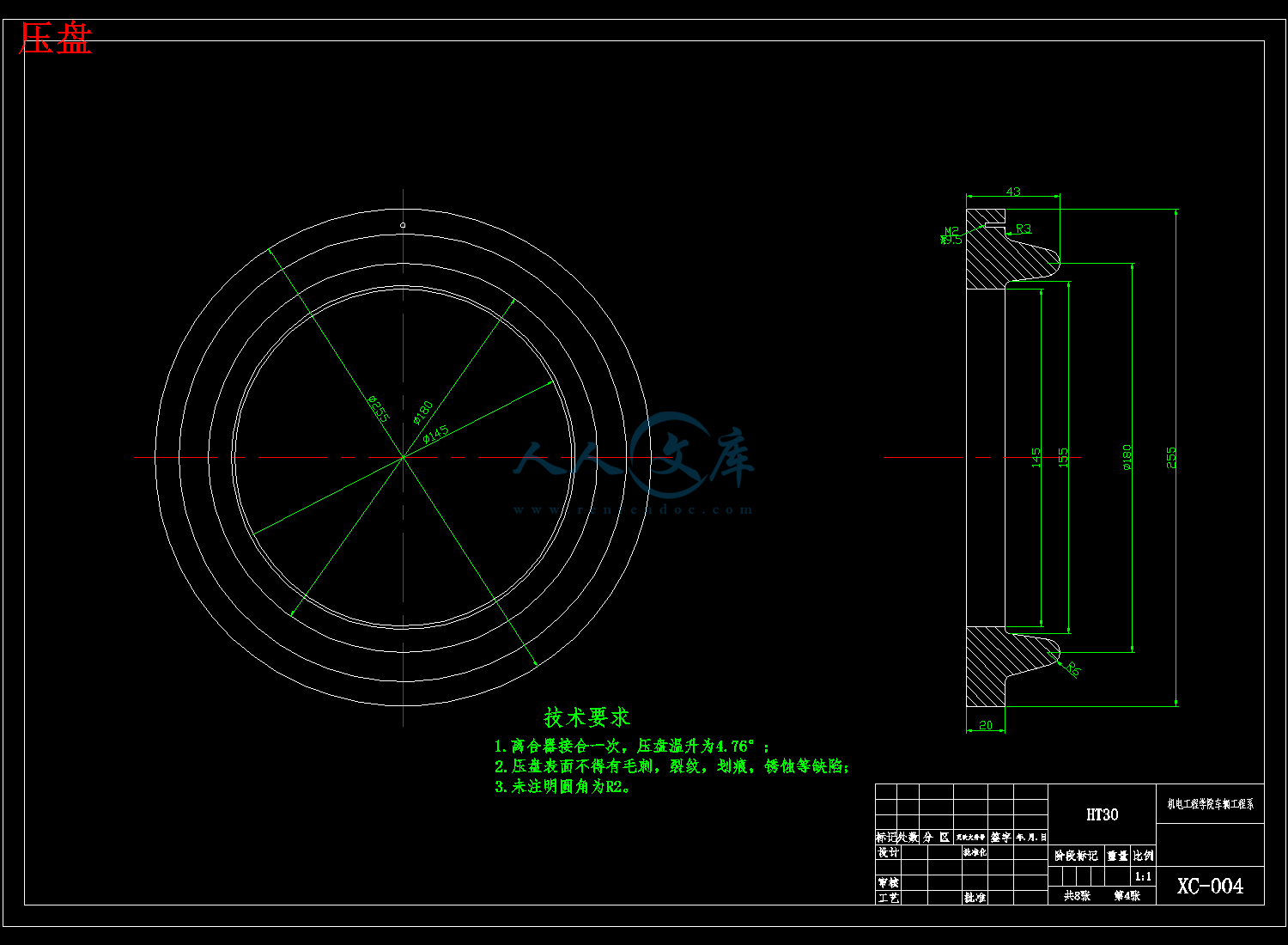
压盘.dwg
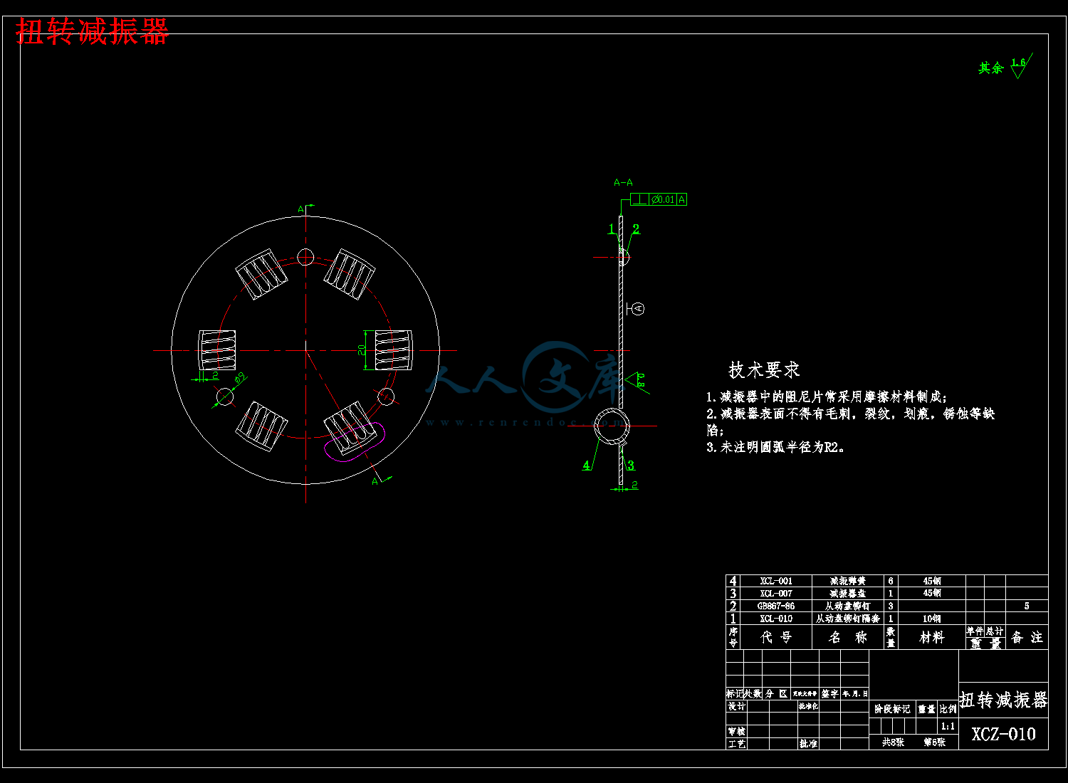
扭转减振器.dwg
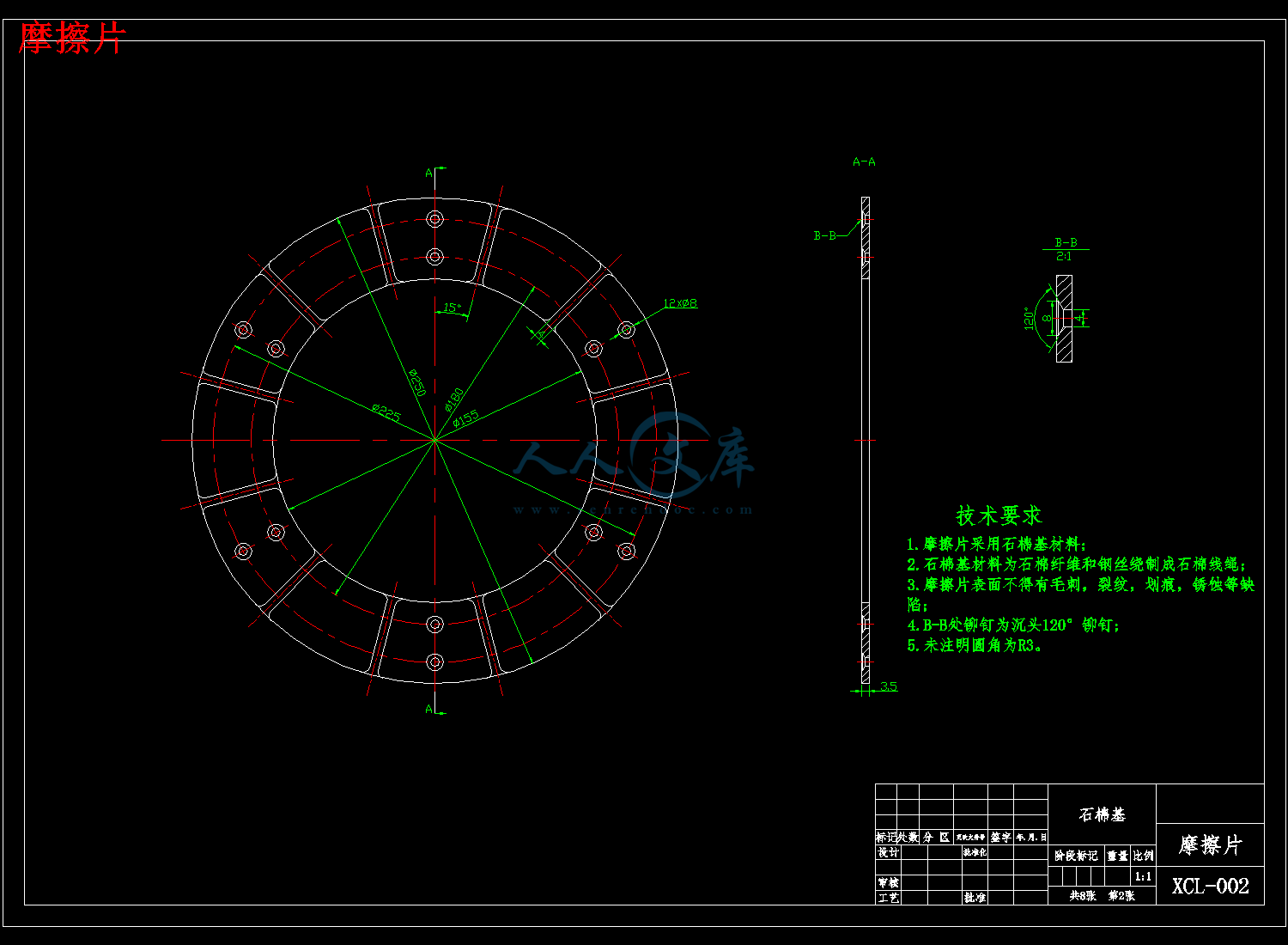
摩擦片.dwg
离合器.dwg
膜片弹簧.dwg
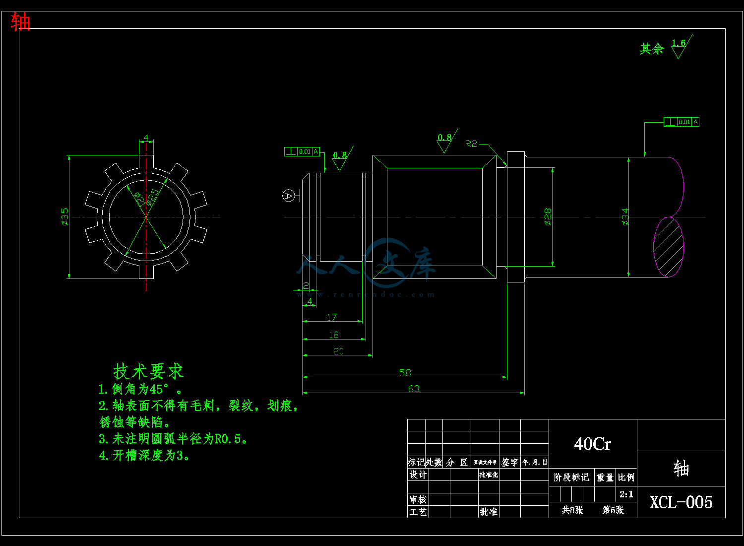
轴.dwg
目录
目录 I
摘 要 III
Abstract IV
1 绪 论 1
1.1 离合器的功能 1
1.2 离合器的种类 1
1.3 轻型货车 2
1.4 膜片弹簧离合器 2
1.5 本论文所需要设计的对象 2
2 膜片弹簧离合器的总体设计 4
2.1 离合器设计分析 4
2.2 离合器主要参数的确定 6
3 从动盘总成设计 9
3.1 从动盘类型选择 9
3.2 从动片设计 9
3.3 从动盘毂的设计 9
3.4 摩擦片设计 11
3.5 扭转减振器的设计 12
4 膜片弹簧设计 15
4.1 膜片弹簧的材料 15
4.2 膜片弹簧的弹性特性 15
4.3 膜片弹簧的基本参数 16
4.4 膜片弹簧数据校核 16
5 压盘与离合器盖的设计 18
5.1 压盘设计 18
5.2 离合器盖的设计 19
6 操纵机构设计轴的选择 21
6.1 操纵机构 21
6.2 从动轴 21
6.3 分离轴承总成 22
7 膜片弹簧离合器装配图 23
8 结论 24
参考文献 25
致 谢 26
3吨载重跃进货车离合器的设计
摘 要
离合器位于发动机与变速器之间,是实现发动机动力传递或分离的装置,在机械传动系统中属于独立部件。本次毕业设计主要是对3吨载重跃进货车的离合器进行设计。首先对离合器的作用及种类进行简单的介绍,因为3吨载重货车属于轻型货车,为保证起步平稳,换挡平顺,所以选用离合器为膜片弹簧离合器。接下来详细说明了膜片弹簧离合器的结构形式,并根据轻型货车的主要参数选择离合器的基本参数,再对离合器主要零部件的尺寸进行设计计算及校核。最后运用CAD绘图软件绘制离合器的零件图及装配图。
关键词:离合器;轻型货车;膜片弹簧


- 内容简介:
-
译文题目: A magnetorheological clutch for efficient automotive auxiliary device actuation 磁流变离合器的高效汽车辅助设备驱动 英语原文A magnetorheological clutch for efficient automotive auxiliary device actuationABSTRACT .In this paper the results of a project funded by Regione Toscana aimed at reducing the power absorption of auxiliary devices in vehicles are presented. In particular the design, testing and application of a magnetorheological clutch (MR) is proposed, aimed at disengaging the vacuum pump, which draws in air from the power-brake booster chamber, in order to reduce the device power absorption.Several clutch preliminary studies done to choose the clutch geometry and the magnetic field supply are illustrated. The final choice consisted in an MR clutch with permanent magnet, which satisfied size, torque and fail-safe specifications. The clutch characteristics, in terms of torque versus slip, were obtained experimentally for three different clutch prototypes on an ad-hoc developed test bench.As result of a preliminary simulation, a comparison between the power absorption of a current production vacuum pump, an innovative vacuum pump and both vacuum pumps coupled with the MR clutch is presented. The New European Driving Cycle is considered for simulating the vacuum pump operation both in urban and highway driving. Results show that the use of the innovative vacuum pump reduces the device consumption of about 35%, whereas the use of MR clutch coupled with the innovative vacuum pump reduces it up to about 44% in urban driving and 50% in highway driving.KEYWORDS. Magnetorheological fluid; Magnetorheological clutch; Permanent magnet; Test bench, Experimental testing; Automotive; NEDC.INTRODUCTIONNowadays, the reduction of consumption and emissions represents, together with safety and comfort issues, some of the leading trends for vehicle development. Fuel saving is promoted by the increasing attention devoted to environment protection and, at the same time, it is enforced by the pressing regulations on emissions (e.g. current EURO 5 and future EURO 6 emission standards).The reduction of consumption and emissions is pursued by different strategies, which involve several research fields. The most radical approach deals with the design and implementation of innovative drive-train technologies, such as hybrid applications for the short to medium term period, or the use of different fuels (e.g. hydrogen, ammonia, bio-fuels etc.) or different energy supply-chain (pure electric vehicles) for the long term period. However, these solutions often present a long time-to-market and, in some cases, collide with energy processing and storage .Another research field deals with the enhancement of transportation efficiency; current trends aim at reducing the consumptions and emissions by enforcing public transportation or encouraging private vehicles sharing.At the same time the main OEMs component suppliers and research institutes have been studying several particular solutions aimed at reducing the incidence of auxiliary device absorption (e.g. oil, water and vacuum pumps, air conditioning system etc.), improving the component efficiency (e.g. bearing resistance, seal friction etc.) and reducing the component mass. In particular, the reduction in consumptions is actually analysed with reference to the NEDC driving cycle, which takes into account several driving cycles including engine warm-up.The reduction of oil pump absorptions has been recently studied in by controlling the oil pressure as a function of the engine speed and engine temperature. Other studies focus on the control of variable displacement pumps on the basis of the engine oil request. In a switchable water pump was designed in order to disconnect the auxiliary device from the engine when the engine temperature results lower than a threshold value.Multiphysics research also led to the use of smart materials in vehicle performance optimization. In 9 and 10 the engine cooling fan is driven by a controllable magnetorheological clutch. The use of smart materials permits the regulation of speed and, consequently, of power absorbed by the cooling fan optimizing its operation on the basis of temperature control (e.g. the cooling fan could be disengaged during engine warm-up). The use of smart materials in the automotive industry has been pursued since many years, especially in suspension design , in order to improve the drivers comfort and the vehicle dynamic performance by changing the apparent viscosity of the MR fluid filling the dampers.In this paper a multiphysics research aimed at reducing the absorption of vacuum pumps in Diesel engines is presented. The activity was carried out in co-operation between Pierburg Pump Technology (Livorno, Italy) and the University of Pisa, the University of Bologna and the Politecnico of Torino (Italy). Aim of the research, which was funded by Regione Toscana in the framework of the “Bando Unico 2008”, was the design of a new vacuum pump, actuated by a magnetorheological clutch.In particular, this paper describes the development of a fail -safe magnetorheological clutch 14 which was designed for disengaging the vacuum pump from the cam-shaft when its operation is not strictly necessary. The mechanical and magnetic design of the clutch, respectively conceived and developed by the Department of Civil and Industrial Engineering and the Department of Energy, Systems, Territory and Constructions of the University of Pisa, have been proposed and discussed in. In this paper, the experimental characteristics of the clutch in the different operating conditions, which were measured on an purposely designed test bench , are discussed in comparison with the absorption data of a vacuum pump currently on the market, in order to evaluate the feasibility of a new integrated MR clutch-vacuum pump system.POWER-BRAKE AND VACUUM PUMP OPERATIONI n conventional cars, the braking maneuver is imposed by the drivers pressure on the brake pedal, but the resultant force on the braking master cylinder is amplified exploiting the difference of pressure between two chambers, one connected with ambient air and one (the booster chamber) with the intake manifold, for a throttled gasoline engine,or to the vacuum pump driven by the cam-shaft in Diesel engines 18 .In case of Diesel engines, starting from atmospheric pressure, the vacuum pump draws in air from the booster chamber till the pressure reaches the steady value pm , as shown in Fig. 1. The emptying time, which is the time taken to reach the pressure steady value pm , results a function of the cam-shaft speed (it is half the engine speed in 4-stroke engines). In Fig.1 the emptying trends are shown with reference to a current production vacuum pump (C.P.) and an innovative one (New), which was designed in the framework of the funded project. The engine speed was set at 4000rpm, which corresponds to 2000rpm at the cam-shaft.If the emptying characteristic is similar for both solutions, significantly different profiles can be found for the absorbed torques, as shown in Fig. 2. The torque profiles were experimentally measured on a vacuum pump test rig. During tests, the oil temperature was imposed at 120C and the torque was measured at several steady speed values for both the current production and innovative vacuum pump, and the data were interpolated by a piecewise function. During operation, once the saturation pressure pm is reached in the chamber, the vacuum pump goes on rotating even if its operation is no longer necessary. The power loss could be avoided by disengaging the vacuum pump. The dissipated power can be easily estimated on the basis of the plots of Fig.2, which give the absorbed torque as a function of the cam-shaft speed.Figure 1: Power-brake booster chamber pressure profile.Figure 2: Vacuum pump torque absorption.VACUUM PUMP DISENGAGING CLUTCHIn order to carry out the disengagement of the vacuum pump, a clutch could be interposed between the can shaft and the vacuum pump with strict packaging requirements. Due to the pressing safety requests of the braking system, the clutch has to be fail-safe. In addition, no axial load must be exerted on the cam-shaft, so a traditional friction clutch could not be used. The design choice fell on the use of a magnetorheological (MR) fluid clutch, thanks to the peculiar properties of MR fluids listed in the next section.Magnetorheological fluidsMagnetorheological fluids are suspensions of micro -sized ferrous particles in a carrier fluid 19. Their main characteristic consists in changing their rheological properties if subjected to a magnetic field. In particular, when not subjected to a magnetic field they behave as Newtonian fluids (N. M.), whereas under the effect of a magnetic field they exhibit a viscoplastic behavior, which can be modeled in first approximation by the Bingham-plastic model . According to this model, the stress versus shear-rate characteristic can be considered as the superposition of a rigid perfectly-plastic Behavior (characterized by a yield stress value y , which is a function of the magnetic field H ) and a linear viscous contribution as shown in Fig. 3.Figure 3: Newton and Bingham modelsAs regards the vacuum pump disengagement, the following favorable properties of MR fluids have to be considered (numerical values are referred to Lord Corporation MRF140CG fluid):- low power loss with disengaged clutch due to low viscosity for the unmagnetized fluid (0.28 Pas);- high engaged clutch transmissible torque due to high yield stress for the magnetized fluid ( 55 kPa at 200 kA/m);- no axial load needed to generate shear stress;- fast switching time (10ms) from unmagnetized to magnetized fluid.Clutch designOn the basis of the design specification listed in Tab. 1, several preliminary design concepts (Fig. 4) were considered in order to define a suitable configuration. The comparative analysis of the possible solutions included several FE magnetic simulations which were carried out by the research team of the Department of Energy, Systems, Territory and Constructions of the University of Pisa.External Diameter 70 mmOverall length 2.5 NmDisengaged torque 0.5NmMaximum speed3000rpmTable 1: Design specifications.The external diameter and the overall length were limited by the available volume in the proximity of the vacuum pump. The engaged clutch had to assure the torque transmission necessary for the vacuum pump operation, whereas the disengaged clutch torque had to be lower than the torque absorbed by the vacuum pump at steady pressure pm (Fig. 1).The maximum speed is equal to the maximum envisaged speed of the cam-shaft.The four basic design given in Fig.4 were taken into consideration. In all solutions with the exception of the first one, the magnetic field is provided by permanent magnets (PM), which assure a fail-safe actuation against possible battery faults. The analysis of the different geometries allowed to confirm, with the support of quantitative numerical values, that, in order to have a high torque it is necessary to put the MR gap at the larger diameter and, at the same time, to achieve a high magnetic field in the MR gap. Those issues make the solution shown in Fig. 4d, which has a relatively large permanent magnet and an outer MR gap, advantageous with respect to the others; such a solution resulted also conveniently simpler than the multi-disc or multi-cylinder configurations.A more detailed discussion of the examined geometries can be found in 15.In addition, in order to compare the capability of the developed prototypes two performance indexes were also proposed in 22: an exploitation index which is a measure of the magnetic design effectiveness and an efficiency index which is a measure of the overall spurious torque, other than the pure viscous one.The former is the ratio between the actual (experimentally measured) magnetorheological torque and the maximum ideal magnetorheological torque, which would be available if the entire MR gap was subjected to a uniform magnetic field (the one which takes the MR fluid to saturation).The latter is the ratio between the ideal spurious torque given by the viscous action of the unmagnetized MR fluid and the actual (experimentally measured) spurious torque, which also includes friction in bearings and seals and any possible unwanted magnetization of the fluid for ineffective shielding of the MR gap.The above indexes are bound in the (0-1) range and can be used to analyze any MR device. In particular, the efficiency index results important in the context of the present research, with respect to the minimization of losses, when the clutch is in the disengaged configuration. Clutch prototypesThree prototypes were manufactured on the basis of the layout shown in Fig. 4(d). Each prototype (Fig. 5) consists of an input and an output coaxially shafts. The gap between the two groups is filled the MR fluid, which can be magnetized by a rare earth NeFeB PM. The PM can slide in a cylindrical room. When the magnet is positioned close to the fluid it assures fluid magnetization and the engaged clutch condition, whereas when it is placed away from the fluid its magnetic field is shielded by a ferromagnetic ring fixed to the input shaft and the clutch results disengaged. 中文翻译磁流变离合器的高效汽车辅助设备驱动摘 要本文由托斯卡纳区政府资助项目的结果,旨在减少在车辆辅助设备的功率吸收。特别是提出设计、测试和磁流变离合器(MR)中的应用,旨在脱离真空泵,它将空气吸入功率制动助力器的增压室,以减少设备的功率吸收。几个离合器做选择,说明离合器几何及磁场供应的初步研究。最后的选择包括磁离合器与永久磁铁,满足大小、扭矩和故障安全规格。离合器的特性,在转矩与滑移方面,实验台上的三个不同离合器原型在一个特设的开发测试平台上实验获得。由于一个初步的模拟,提出了当前生产真空泵、一种创新的真空泵和加磁离合器两真空泵功率吸收的比较。新的欧洲行驶工况考虑模拟真空泵运行这两个在城市和公路驾驶。结果表明,使用创新的真空泵降低设备消耗的约35%,而加上创新的真空泵的磁离合器的使用降低了它在市区开车约占44%和50%在高速公路上行驶。关键字 磁流变液;磁流变离合器;永久磁铁;试验台;实验测试;汽车;NEDC。概况如今,减少消耗和排放量表示的内容以及安全和舒适的问题,是一些车辆发展的主导趋势。燃料节约是促进越来越多的关注,致力于环境保护,并在同一时间,它是强制性的排放法规(如目前欧元 5 和未来 6 欧元排放标准)。消费和排放量的减少是由不同的策略,涉及多个研究领域的追求。最激进的方法涉及创新的驱动列车技术,如混合应用的短期至中期阶段,或使用不同的燃料(如氢,氨,生物燃料等)或不同的能源供应链(纯电动汽车)长期周期的设计和实施。然而,这些解决方案往往存在很长一段时间的市场,在某些情况下,碰撞的能量处理和存储。另一个研究领域涉及提高运输效率,目前的趋势旨在减少消耗和排放量可实行公共交通或鼓励私家车共享。同时主要的OEM零部件供应商和研究机构一直在研究几种特定的解决方案,旨在减少辅助装置吸收率(如油、水和真空水泵、空调系统等),提高组件效率(例如轴承阻力,密封摩擦等)和减少组件质量。尤其是,在消费减少的实际上是参照了NEDC循环分析,它考虑到包括发动机预热的不同驾驶循环工况。最近关于石油泵吸收减少的研究,通过控制油压力随发动机转速和发动机的温度。其他的研究专注于可变排量泵的基础上,发动机机油的控制要求。其中可切换的水泵被为从发动机断开辅助设备,当发动机温度结果低于一个阀值。多场物理研究也导致在车辆性能优化的智能材料的使用。由可控磁流变离合器驱动发动机冷却风扇。智能材料的使用允许转速调节,因此,电力由冷却风扇温度控制的基础上优化其运行吸收(例如冷却风扇能脱离发动机预热期间)。很多年以来智能材料一直在汽车工业中使用,特别是在悬架设计,提高驾驶员的舒适和整车动态性能,通过改变磁流变液填充阻尼器的表观粘度。本文提出了多场物理的研究旨在减少柴油发动机真空泵的吸收。是皮尔博格泵技术(利沃诺,意大利)、比萨大学、博洛尼亚大学和都灵理工大学(意大利)之间的合作开展的活动。本研究,是由托斯卡纳区政府资助的“Bando Unico2008年”的框架,目的是通过驱动磁流变离合器,设计一个新的真空泵。特别是,本文介绍了的故障的旨在切断真空泵从凸轮轴时其操作不是严格必要的安全磁流变离合器。分别对比萨大学土木与工业工程系、能源、系统、国土、建筑等部门的机械和磁力设计进行了构想和探讨。在本文中,在不同的工况下,在一个故意设计的试验台上进行了测量,再比较真空泵,目前在市场上的吸附数据,以评估一个新的集成磁离合器真空泵系统的可行性。动力制动和真空泵操作传统的汽车,制动动作是踩刹车踏板,由此产生的驱动压力,制动主缸上的力被放大,利用两个腔,一个环境空气(增压室)与进气歧管,节流的汽油发动机,与空气之间的压差或到真空泵驱动凸轮轴柴油机。在柴油发动机的情况下,从大气压开始,真空泵吸进空气从增压室直到压力达到稳定值pm,如图1所示。排空的时间,是达到压力稳定值pm所需的时间,结果是一个凸轮轴速度的函数(它是在四冲程发动机的一半发动机转速)。图1示参照当前生产真空泵
- 温馨提示:
1: 本站所有资源如无特殊说明,都需要本地电脑安装OFFICE2007和PDF阅读器。图纸软件为CAD,CAXA,PROE,UG,SolidWorks等.压缩文件请下载最新的WinRAR软件解压。
2: 本站的文档不包含任何第三方提供的附件图纸等,如果需要附件,请联系上传者。文件的所有权益归上传用户所有。
3.本站RAR压缩包中若带图纸,网页内容里面会有图纸预览,若没有图纸预览就没有图纸。
4. 未经权益所有人同意不得将文件中的内容挪作商业或盈利用途。
5. 人人文库网仅提供信息存储空间,仅对用户上传内容的表现方式做保护处理,对用户上传分享的文档内容本身不做任何修改或编辑,并不能对任何下载内容负责。
6. 下载文件中如有侵权或不适当内容,请与我们联系,我们立即纠正。
7. 本站不保证下载资源的准确性、安全性和完整性, 同时也不承担用户因使用这些下载资源对自己和他人造成任何形式的伤害或损失。

人人文库网所有资源均是用户自行上传分享,仅供网友学习交流,未经上传用户书面授权,请勿作他用。
 川公网安备: 51019002004831号